

Page 1
TDEMI 40G
- 162.5 MHz full real-time analysis
bandwidth up to 40 GHz
- Measurement according to MIL and
DO standards starting from 10 Hz
- 4000x faster than conventional EMI
receivers
The TDEMI 40G system covers the frequency range 10 Hz
to 40 GHz in its standard conguration and is ready for
measurements in civil applications and especially for testing in military applications and also avionics. All IF bandwidths according to MIL461 and DO160 are available in
the preselected spectrogram mode of the instrument
also. The fully gapless real-time analysis bandwidth of
162.5 MHz of the spectrogram mode up to 40 GHz makes
the TDEMI 40G unique in the instrumentation market and
provides an ideal tool for real-time EMC debugging up to
40 GHz. It supports the user in detecting, localizing, observing and analyzing emissions and in nding solutions
for reduction EMI of components and systems for military
and avionic industry.
The receiver mode of the TDEMI 40G system can be used
for full compliance EMC tests according to CISPR, MIL461
and DO160 standard. The huge computation power of
the digital signal processing unit of the TDEMI allows to
reduce test time up to a factor of 4000 in comparison to
traditional superheterodyn based receivers. A fast measurement at all frequencies and with higher frequency selectivities at the same time can be performed yielding in
a reduced measurement uncertainty.
eral thousand receivers using the short-term fast Fourier
transform (STFFT) allows the TDEMI to reduce the overall testing time signicantly. Especially for longer dwell
times the scan time remains very short compared to superheterodyne EMI receivers and right after the results
are measured at all frequencies all the data can be stored
and documented. Thus, it is easily possible to reduce the
measurement uncertainty even further by increasing the
dwell time, which means a longer observation time at
each frequency point. But not only broadband, also single frequencies can be measured in the same way. For a
higher sensitivity in the upper frequency range the instrument comes with a broadband preselected low noise
amplier already integrated in its standard conguration.
Especially in the lower frequency range up to several
hundred MHz a large number of frequency points have to
be measured. The parallel digital implementation of sev-
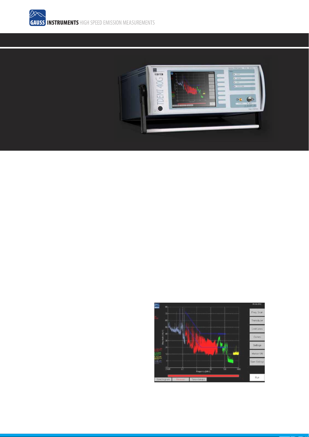
Fig. 32 – Measurement of a switched power supply according to DO160.
Measured emissions above limit line for peak detector in band B.
30
Page 2

TDEMI 40G Specications
FREQUENCY RANGE
10 Hz – 40 GHz
REFERENCE (OCXO)
Aging < ± 3.5 ppm / 15 years
Temperature Drift (0 .. 60° C) ± 1 x 10e-8
SSB Phase Noise (1 Hz BW) 1 Hz
(typ. @ 12.8 MHz) 10 Hz -120 dBc/Hz
RECEIVER MODE (CISPR Standard)
IF Bandwidth 200 Hz Band A
IF Filter: Gaussian Shaped Filter, Specications according to
CISPR 16-1-1, Bandwidth Deviation < 10 %
Displayed Average Noise Level (Input Level < 85 dBμV Sinus):
< 0 dBμV (typ. -3 dBμV)
Measurement at about 700 Frequencies in parallel
Frequency Step < 100 Hz
IF Bandwidth 9 kHz
IF Filter: Gaussian Shaped Filter, Specications according to
CISPR 16-1-1, Bandwidth Deviation < 10 %
Displayed Average Noise Level (Input Level < 65 dBμV Sinus):
< -15 dBμV (typ. -19 dBμV)
Measurement at 4096 Frequencies in parallel
Frequency Step < 400 Hz
IF Bandwidth 120 kHz
IF Filter: Gaussian Shaped Filter, Specications according to
CISPR 16-1-1, Bandwidth Deviation < 10 %
Displayed Average Noise Level (Input Level < 65 dBμV Sinus):
< -3 dBμV (typ. -6 dBμV)
Measurement at 1024 Frequencies in parallel
Frequency Step < 800 Hz
IF Bandwidth 1 MHz
IF Filter: Gaussian Shaped Filter, Specications according to
CISPR 16-1-1, Bandwidth Deviation < 10 %
Displayed Average Noise Level (Input Level < 65 dBμV Sinus):
< 6 dBμV 1 MHz – 1 GHz
< 8 dBμV 1 GHz – 1.15 GHz
< 3 dBμV 1.15 GHz – 6 GHz
< 15 dBμV 6 GHz - 18 GHz
Measurement at 128 Frequencies in parallel
Frequency Step < 800 Hz
RECEIVER MODE (MIL/DO Standard)
IF Bandwidth 10 Hz (10 Hz - 10 kHz)
IF Filter: Gaussian Shaped Filter, Bandwidth Deviation < 10 %
Detector Modes: Peak, Average, RMS
Displayed Average Noise Floor typ.: < 40 dBμV
< 25 dBμV (500 Hz - 1 kHz)
IF Bandwidth 100 Hz (1 kHz - 150 kHz)
IF Filter: Gaussian Shaped Filter, Bandwidth Deviation < 10 %
Detector Modes: Peak, Average, RMS
Displayed Average Noise Floor typ.:
IF Bandwidth 1 kHz (10 kHz - 30 MHz)
IF Filter: Gaussian Shaped Filter, Bandwidth Deviation < 10 %
Detector Modes: Peak, Average, RMS
Displayed Average Noise Floor typ.:
< -27 dBμV > 1 MHz
IF Bandwidth 10 kHz (150 kHz - 40 GHz)
IF Filter: Gaussian Shaped Filter, Bandwidth Deviation < 10 %
Detector Modes: Peak, Average, RMS
Displayed Average Noise Floor typ.: < -17 dBμV (1 MHz - 1 GHz)
IF Bandwidth 100 kHz (150 kHz - 40 GHz)
IF Filter: Gaussian Shaped Filter, Bandwidth Deviation < 10 %
Detector Modes: Peak, Average, RMS
Displayed Average Noise Floor typ.: < -5 dBμV (1 MHz - 1 GHz)
IF Bandwidth 1 MHz (150 kHz - 40 GHz)
IF Filter: Gaussian Shaped Filter, Bandwidth Deviation < 10 %
Detector Modes: Peak, Average, RMS
Displayed Average Noise Floor typ.:
Detector Modes: Peak, Quasi-Peak, Average, RMS, CISPR-AV
Detector Modes: Peak, Quasi-Peak, Average, RMS, CISPR-AV
Detector Modes: Peak, Quasi-Peak, Average, RMS, CISPR-AV
Detector Modes: Peak, Average, RMS, CISPR-AV
-95 dBc/Hz
100
Hz -140 dBc/Hz
1 kHz -145 dBc/Hz
< 30 dBμV
< 5 dBμV (10 kHz - 150 kHz)
< 6 dBμV 1 MHz - 1 GHz
< 8 dBμV 1 GHz - 1.15 GHz
< 3 dBμV 1.15 GHz - 6 GHz
< 20 dBμV 6 GHz - 40 GHz
(10 Hz - 500 Hz)
WEIGHTED REAL-TIME SPECTROGRAM
Weighted Spectrogram Mode Peak, Average, RMS
Time-domain Fully gapless
Frequency Step 158 kHz for 120 kHz
1.2 MHz for 1 MHz
Frequency Step Interpolation 40 kHz for 120 kHz
300 kHz for 1 MHz
Frequency Span > 150 MHz
IF Bandwidths CISPR 200 Hz, 9 kHz, 120 kHz, 1 MHz
IF Bandwidths MIL/DO 10 Hz, 100 Hz, 1 kHz,
10 kHz, 100 kHz, 1 MHz
Minimum Time Step 50 ms
TIME-DOMAIN ANALYSIS (RF)
Bandwidth 1 GHz
Sampling Rate 2.6 GS/s
Acquisition Memory 32000 Samples
ABSOLUTE MAXIMUM RATINGS (ATTENUATION 0 dB)
Maximum DC Input Level, Pulse 6 V
RF-CW Signal 120 dBμV
INDICATION (ATTENUATION 0 dB)
Maximum DC Input Level, Pulse 5 V
RF-CW Signal 65 dBμV
ATTENUATOR
0 - 70 dB, 10 dB Steps
INTERMODULATION, NONLINEARITIES
CW Signals: Two Tone
Harmonics (> 40 dBμV, > 1 MHz) < -40 dB (typ. <-50 dB)
Inherent Reception Points < -40 dB (typ. <-50 dB)
Total Dynamic Range (120 kHz IF Bandwidth) > 140 dB
INHERENT RECEPTION POINTS (ATTENUATION 0 dB)
Inherent Reception Point 1⁄4 ADC Sampling Rate:
<< 25 dBμV (using Multi-sampling < -15 dBμV)
Further Inherent Reception Points
<< 5 dBμV (using Multi-sampling < -15 dBμV)
MEASUREMENT TIME
1 ms – 60 s (Average, RMS)
1 ms – innite (Peak, Quasi-Peak)
MEASUREMENT ACCURACY
Sinusoidal Signals (9 kHz - 1 GHz) ± 1 dB
Pulses according to CISPR 16-1-1
RF INPUT
50 Ohm
VSWR < 3.0 typ., 1 GHz - 40 GHz
VSWR < 1.2 typ., 10 Hz - 1 GHz, with 10 dB Attenuation
REMOTE CONTROL
Ethernet (LAN), Commands according to SCPI Standard
DISPLAY
XGA 8,4” 800 x 600 True Color
Touchscreen
PC
Intel Celeron M 1.86 GHz, 1 GB RAM, 160 GB Hard Disk
Interface: USB, Ethernet, VGA, serial, IEEE 1394, Audio
Windows XP
POWER SUPPLY
230 V, 50 Hz or 110 V, 60 Hz
WEIGHT
ca. 35 kg
MAIN OPTIONS
PRE - UG Preselection Band A
SW - UG Preselection Band B
LISN - UG
LISNCable - UG
TG - UG Carrying Handle
PC - UG Intel Core 2 Duo, 2.16 GHz,
2 GB RAM, 320 GB Hard Disk
KB - UG Compact Keyboard incl. Touchpad
RG - UG Report Generator
50
CAL - UG Manufacturer Calibration with Certicate
CALD - UG DKD Calibration with Certicate
CLICK - UG Click Rate Analyzer, fully integrated
SLIDE - UG Software for Disturbance Power Measurements
Controller for Measuring Accessories (TTL, 5V)
Customized Control Cabel for Accessories, e.g. LISN
< -40 dB (typ.
-53 dB)
 Loading...