

Page 1
FALCON™
Models TA220-1000 Series
DATA ACQUISITION SYSTEMS
Stand-alone & with Recorder
Portable, 1 to 16 Channels
The SOLTEC Model TA220-1000 series are data acquisition systems with enhanced functions
for color data display, acquisition, and analysis. Three mainframe models, TA220-1100,
TA220-1200, and TA220-1300 are available. The TA220-1100 features data monitoring and
acquisition. The TA220-1200/1300 units feature a waveform printing chart recorder feature
in addition to the functions of the TA220-1100. All mainframes accept a wide selection of
plug-in signal conditioning amplifiers, a wealth of calculation and analysis functions,
and three types of communication interfaces to make each TA220-1000 series unit a versatile,
portable data acquisition system, memory recorder, data logger, transient recorder,
and real-time recorder, all-in-one.
Page 2
FEATURES
RECORD INPUT SIGNALS IN REAL TIME
Selectable Functions
•
FFT Analysis, Waveform Judgement, and
lnterfaces(GP-IB and SCSI) are available options.
Multi-channel Support
•
Up to 16-Channels of measurement are possible
in this compact unit using dual channel plug-in
amplifier modules.
Wide Variety of Input Signal Conditioners
•
12 & 16 bit high-resolution plug-in signal input amps
support voltage, temperature, vibration, strain and
rotation encoder pulse measurements at sampling
speeds up to 1MS/s (1µs).
Color LCD Display
•
A 10.4 inch TFT color LCD display with a touch
sensitive panel offers easier operation.
Long Term Data Storage
•
Long term data acquisition (storage) is possible
at a sampling speed of 200µs by storing data on a
Magneto Optical (MO) hard drive with removeable
media (up to 640 MBytes) or on flash memory cards.
Since the recorded data is in a digital format
(binary or CSV), data analysis after recording and
long term data management, which were impossible
with chart data, can be easily performed.
Modem and Fax Transmission Functions
•
Increase Measurement Efficiency
Long distance measuring using a telephone line
is possible by connecting to a modem. Automatic
data transmission to a fax machine during data
acquisition is also possible.
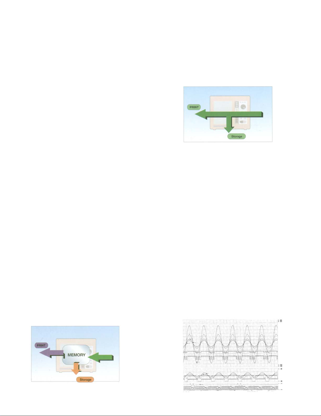
(REAL TIME RECORDING)
Real Time Signals can be monitored on the screen
while storing on MO Drive, Memory Card or Disk.
Storage rates range from 200µs to 100s. Loop storage
mode ensures that latest data is always saved.
TA220-1200/1300 can print on a chart at speeds up to
25/200mm/s. Choose WAVEFORM, XY,
or ALPHANUMERIC Datalogger print format.
The monitored waveform is displayed in the same
format as data being printed.
SIMULTANEOUS MEASUREMENT OF LONG
TERM TREND & TRANSIENT PHENOMENA
(TRANSIENT RECORDING)
Transient recording combines Real Time and Memory
recording. While Recording in Real Time, 'Snapshots'
of High-Speed transients are stored into memory. After
Recording session, both the long term and higher
resolution 'snapshot' data are available.
RECORD HIGH SPEED PHENOMENA
TO MEMORY (MEMORY RECORDING)
High Speed signals can be recorded into built in
memory (up to 2Mdata/ch) at sample rates of
1µs to 1s. Memory can be divided into blocks
for more verstility. Recorded data is displayed
on screen and can be automatically or manually
stored, printed on chart (TA220-1200/1300 only),
transmitted to a fax machine, or sent via modem
to a computer.
The monitored waveform is displayed in the same
formal as the recorded data.
APPLICATION SOFTWARE (Option)
View files, manipulate data, communications, set-up,
control, analyze files, export to spreadsheets,
network/ethernet interface, etc.
PRINT EXAMPLE
Page 3

SELECT EXPANSION FUNCTIONS
PLUG-IN SIGNAL INPUT AMPLIFIER
ACCORDING TO MEASUREMENT NEEDS
Two expansion functions are provided as option:
FFT (Option)
•
The following eight functions are supported:
Linear spectrum, power spectrum, RMS spectrum,
power spectrum density, octave analysis, transfer
function, cross power spectrum, and coherence function.
Waveform Judgement (Option)
•
Waveform judgment option compares incoming
waveforms to waveforms stored in memory. If the
incoming waveform is out of tolerance, a trigger is
activated.
ARITHMETIC OPERATION (Standard)
Provides arithmetic operations on data located in
specified areas of memory. The results of
operations are displayed in the screen and stored
in the form of a waveform or a file.
Operations Include: Four (4) basic arithmetic
operations, maximum, minimum, P-P value,
average area, RMS, standard deviation, rise time,
fall time, absolute value, differential, integral,
linear/quadratic differential, single/double integral,
square root, exponent, common logarithm,
moving average, and trigonometric functions
(sine, cos, tan, asin, acos, and atan).
DISPLAY EXAMPLES
Monitor data during
input amplifier setup
Replay monitor Customized display of
User customized display;
channelized, overlap, etc.
event signals
MODULES
Amplifiers are available to support a wide range of
measurement conditions. The plug-in module
design allows easy configuration changes.
2CH High
Resolution
Voltage Amp.
AP11-101
2CH High
Speed Voltage
Amp.
AP11-103
2CH TC
Voltage Amp.
AP11-106
1CH TC
Voltage Amp.
AP11-107
Event Amp.
AP11-105
2CH AC
Strain Amp.
AP11-104
2CK
DC
Strain Amp.
AP11-110
2CH RMS •
Vibration Amp.
AP11-109
2CH FFT Amp.
AP11-102
1CH F/V
Converter
AP11-108
16 bits 10µs
12 bits 1µs
15 bits 10µs
14 bits 10µs
1µs
16 bits 10µs
16 bits 10µs
16 bits 10µs
16 bits 10µs
16 bits 10µs
High resolution voltage
amplifier with 500V
maximum input
High speed voltage
amplifier with 500V
maximum input
Thermocouple and
voltage
Thermocouple and
voltage amplifier
Logic input (8CH)
Strain gage and straingage sensor input with
high resistance to noise
from power line
Strain gage and strain-
gage sensor input with
high frequency response
DC amplifier. 500V
max. input with charge
sensor power supply,
RMS converter and
bandpass filter
Voltage amplifier. 500V
max. input with antialiasing filter and power
supply for charge sensor
Converts frequency
(e.g. pulses) into voltage
Page 4

SPECIFICATIONS
Basic Specifications
Display 10.4 inch TFT color LCD display.
Effective display area 211.2mm (8.32")
× 158.4mm (6.24") (640 × 480 dots)
Printer (Models TA220-1200 &TA220-1300)
Recording method
Thermal array head and thermosensitive
chart
Paper width
Effective recording
width
Channel print
219.5mm (8.64")
200mm (7.87") FS in 1 div. to 10mm FS
in 16 div. variable
Prints channel No. in the vicinity of the
printed waveform
Battery Backup
Backup for main unit settings, recording
conditions Backup time : Approx. 1 month
Storage Devices
Built-in 3.5 inch FDD (1.25MB/1.44MB)
and PC card slot (ATA flash memory card,
SRAM card). Option: MO Disk Drive
w/ removeable cartridge 640, 540, 230,
128MB media, Internal or External
versions; Zip™ Drives
Interface Unit
Standard RS-232C unit (38400 to 2400bps)
Option: GP-IB (IEEE488 compliant)
Option: SCSI (half pitch 50 pin type)
Remote Terminal
Features
Start/stop, mark print, and paper feed
controlled by external signal.
Input: Sync pulse, Protect pulse.
Output: Waveform judge, Error
Clock function
Stability : Daily error ± 35PPM
(at normal temp.)
Operating
Environment
Temperature: 0 to 40°C
(5 to 40° C when FFD is operating)
Humidity: 35 to 80%RH
(without condensation)
Vibration: MIL-STD-810E compliant
(except during FDD or MO operation)
Power Supply
90 to 132V or 180 to 264V AC.
Specify at time of order
Frequency: 47 to 63Hz
Option: DC power unit: 11 to 28V DC
Power Consumption
(Max)
TA220-1100: approx. 85VA
TA220-1200: approx. 180VA
TA220-1200/1300: Approx. 180 VA/400V A
(approx. 85VA stand-by)
Dimensions
Weight
approx. 369.5 (4.6")(W) × 150.5 (5.9")(H)
× 301(11.9")(D)mm
Approx. 7 kg (15 Ib)
Other Specifications
Printing functions (TA220-1200 & TA220-1300)
Data information
Measurement mode, year/month/day,
measurement start time, data No.,
trigger condition (trigger point,
year/month/day, time), sampling
speed, paper speed, time axis, etc.
are printed. Modes can be turned
ON or
OFF.
Channel
Information
Event Print
Signal input amp. settings are printed.
Modes can be turned On or OFF.
In real-time mode, a manual or
external input event is marked on
chart along with date and time.
List Print
Date, time, measurement mode, data
No., print format, paper speed, sampling
speed, scale print, backlight auto-off,
auto-start, trigger mode, source
channel, recording operation and
file settings are printed.
Screen Copy
Function
A4 Report Output
Any screen can be printed or saved
to .BMP file.
Registers users comments and
prints them together with waveform
on A4 format.
Printing Line
Width
Key Lock Function
Printing line width can be set for each
channel. (1, 2, 3, 4 dots)
Locks keyboard to prevent erroneous
operation.
Internal Storage of
Recorder Setups
4 different recorder setups can be
saved or recalled from internal memory.
Setups include amplifier settings.
Engineering Unit
Conversion
Auto-Start
Physical value conversion, full-scale
modification of display.
After a power failure, recording is
resumed. (Except during data filing)
Auto-Setup
Function
Automatically reads the recorder
setup from floppy disk when power is
turned on. (Desired setup must be
previously stored on the floppy disk)
Screen Image
Store
Help Function
Stores a screen image in .BMP file.
Useful for reports.
Displays how to operate,
cautions, etc.
Data Storage Mode
Data Recording
Function
Recording Speed
Recording
Method
Stores measured data in real time to a
memory medium (Real-time data storage).
200µs to 1s, user set. External
synchronization possible.
Linear Buffer: Stores set no. of data
samples and stops.
Loop (ring buffer): Overwrites old data
with most recent events.
AC Bridge Power Supply Unit (Option)
Function
Bridge power source for 2CH AC
strain amplifier model AP11-104.
Power Source
Synchronism
2Vrms, sine wave 5kHz.
Synchronizes with other TA220-1000
series units in which an AC bridge
power unit is installed.
Page 5

SPECIFICATIONS (cont.)
Memory Mode
Data Recording
Measurement
Once, Repeat, Endless
Operation
Memory Capacity
256kW/CH (Option: 1MW/CH)
When using dual channel
modules, module memory may
be combined to provide up to
2 Mega Data on one channel.
Memory Divisions
Sampling
1, 2, 4, 8, 16, 32, 64 and 128
1µs (1MS/s)~1s (1S/s), User
sets sampling rate in 1µs steps.
External synchronization
possible.
Display (Replay Monitor)
Waveform
X-Y
Magnification : x 5 to x 1/1000
User can select any channel
to be X-axis, and any other
channel(s) for Y-axis.
Printing (Models TA220-1200/1300 only)
Waveform
Print density : Voltage axis:
8 dots/mm
Time axis : 10/80 dots/mm
Magnification : × 5 to × 1/1000
Alphanumeric
Read out interval : Selectable
1 to 1000 data measurements.
X-Y
User can select any channel
to be X-axis and any other
channel for Y-axis.
Effective print range :
200mm x 200mm
Print density : 400 dots (X-axis)
x 400 dots (Y-axis)
Memory Storage
Captured data can be saved
as binary or CSV files.
Transient Mode
Transient Printing (TA220-1200/1300)
Function
Normally operates in the real-time
mode. When a trigger is detected,
transient is recorded to memory.
Real-time Set-up
Memory Set-up
See "Real-time Mode".
See "Memory Mode".
Transient Storage
Function
Normally operates in real-time
mode. Transient data is saved in
memory when trigger is detected.
When recording finishes, the
memory data is stored.
Real-time Section
See "Data Storage" in the
Real-time Mode.
Memory Section
See "Memory Storage" in the
Memory Mode.
Real-time Mode (TA220-1200/1300)
Waveform Printing
Measurement
Start
Paper Speed
Start Key, Trigger, Date/Time or
Interval.
25mm/s (200mm/s,TA220-1300)
to 1 mm/min, user set.
External synchronization provided.
Frequency
Characteristics
DC~100kHz (sampling rate 10
points/cycle), Varies depending
on the input amplifier.
Print Density
Voltage axis : 8 dots/mm, Time
axis: 10 dots/mm (80 dots/mm,
TA220-1300)
Print Length
Continuous, or 1 to 1000
divisions-shot feed.
Alphanumeric Format
Sampling
1 second to 1 hour per sample.
External synchronization possible.
Print Length
Continuous, or 1 to 1000 data
samples shot feed.
X-Y Print
Operation
User can select any channel to
be X-axis and any other channel(s)
to be Y-axis.
Continuously measures until the
Stop key is pressed. Pause mode
provided.
Effective Print
200mm x 200mm
Area
Print Density
400 dots (X-axis) x 400 dots
(Y-axis)
Print Speed
Data Storage
10ms or more
Stores the measured data in a
memory device in real-time.
Storage rate: Synchronized with
paper speed.
Waveform Printing(TA220-1200/1300)
Function
Prints the waveform of input
signal.
Paper Speed
25/200 mm/s~1mm/min, user set.
(Independent of sampling speed)
External synchronization possible.
Frequency
Characteristics
DC to 100kHz (sampling rate
10 points/cycle). Varies depending
on the input units.
Print Density
Voltage axis: 8 dots/mm,
Time axis: 10 dots/mm
(80 dots/mm, TA220-1300)
Print Length
Continuous or 1 to 1000 divisions
shot-feed
12977 Arroy o Stre et • San Fernando, CA 91340-1548
(800) 423-2344 • (818) 365-0800 • Fax: (818) 365-7839
E-mail: info@SoltecCorp.com • www.SoltecCorp.com
Page 6

SPECIFICATIONS (cont.)
Trigger Specifications
Trigger Mode
Trigger Source
Trigger Setting
Related Functions
RS-232C Interface (Standard)
Remote Control
Modem Control
FAX Transmission
OR, AND, A then B, WINDOW
Input signal; Time trigger (start time,
end time, measurement interval);
Manual trigger; External trigger.
Amps other than Event Amp (AP11-105)
Trigger slope Q or Q, OR, AND,
A then B, WINDOW (Outside or Inside).
Level setting : Can be Set with
engineering units, e.g., PSI or Volts.
Event amp (AP11-105)
State setting: H, L or OFF can be set
for each each input.
When OFF, trigger is not active.
Trigger setting : AND or OR of the
state setting for CH1 to CH8.
Pre-trigger, trigger path count, trigger
filter, trigger mark
Controls the main unit from a computer
via RS-232C cable.
Communicate between a computer
and the TA220-1000 Series unit via
modem on telephone line.
Transmits measured waveform
using a FAX modem connected to
RS-232C port.
GP-IB Interface (Option)
Remote Control
SCSI Interface (Option)
FFT (Option)
1 Signal Analysis
2 Signal Analysis
Window Function
Additional
Process
Analysis
Frequency
Resolution
Controls the TA220-1000 Series unit
from a computer via GP-IB cable.
Stores data to external memory
devices, such as MO, PD, or ZIP™.
Linear spectrum, power spectrum,
RMS spectrum, power spectrum
density, and octave analysis (1/1, 1/3).
Transfer function, coherence function,
and cross-power spectrum.
Rectangular, hanning, hamming,
exponential, and force.
Simple additional average (time axis),
simple additional average
(frequency axis), exponential weighted
average (frequency axis), and peak hold.
400kHz, 200kHz, 80kHz, 40kHz, 20kHz,
10kHz, 5kHz, 2kHz, 1kHz, 500Hz, 200Hz,
100Hz, 50Hz, 20Hz, 10Hz
Real-time: 400, 800, 1600 data samples.
Memory Mode: 1000, 2000, 4000
data samples.
EXTERNAL VIEW
Printer section
(TA220-1200/1300)
GP-IB
(Option)
Color LCD
display
RS-232C
Operation
panel
Remote Control Inputs
Plug-in Signal Input Amplifier Module
FDD
AC power
AC strain gage bridge power (Option)
line
SCSI (Option)
SCSI unit is the interface to allow MO, PD, or Zip™
to be used as external storage devices.
PC card slot
ATA flash cards and SRAM cards can be used.
12977 Arroyo Street, San Fernando, CA 91340-1548
800-423-2344 • 818-365-0800 • Fax 818-365-7839
Email: lnfo@SoltecCorp.com • www.SoltecCorp.com
© 2000 SOLTEC Corporation 8K00/10M
 Loading...