

Page 1
Technical Data Sheet
™
Site Master
Handheld Cable & Antenna Analyzer
Featuring Classic and Advanced Modes
S331L
2.0 MHz to 4.0 GHz Cable & Antenna Analyzer
50 MHz to 4.0 GHz Power Meter
Introduction
Anritsu introduces its ninth generation, compact handheld Cable & Antenna Analyzer for installation and maintenance of antenna systems.
Optimized for field use Easy to use Efficient sweep management
• > 8 Hour Battery Life
• Instant On from Standby Mode
• Highest RF Immunity
• Built-in InstaCal
- Fast, One-connection Calibration
• FlexCal
• Built-in Power Meter
• Rugged and Reliable
• Impact, Dust, and Splash Resistant
• Smallest, Lightest Site Master
™
- One Calibration for All Frequencies
™
Module
Calibration
™
• Integrated Help Function
• S331D-like Classic Mode
• S331E-like Advanced Mode
- Additional Markers
- Customizable Shortcuts
- Full-screen View
• Multiple USB Ports
• 800 x 480 7” TFT Touch Screen
- Alphanumeric Keyboard
- EZ Name Quick Matrix
• Backlit Keypad
• Internally Store >1000 Files
- Sweeps, Setups, Screen Shots
• Fast Preview of Stored Sweeps
• Line Sweep Tools (LST) Software
- Edit Sweeps, Rename, Archive
- Generate PDF or HTML Reports
• Standard *.dat Sweep File Format
• Compatible with HHST
- Widely Accepted by Operators
• SweepMasters DIRECT
- Online Trace Delivery Service
™
Site Master
B
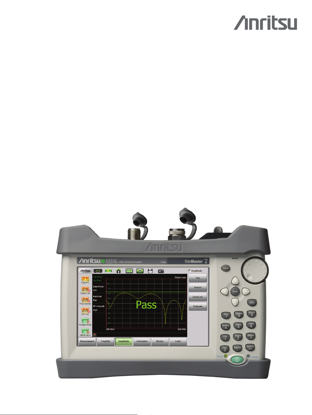
Compact Size: 250 mm x 177 mm x 61 mm (10.0 in x 7.1in x 2.4in), Lightweight: < 2.0 kg (4.4lb)
S331L Cable & Antenna Analyzer Featuring 7.0" Daylight Viewable Touch Screen
Page 2

Specifications Site Master™ S331L
Cable and Antenna Analyzer
All specifications and characteristics apply to revision 1 instruments under the following conditions, unless otherwise stated: 1) Instrument within its recommended calibration cycle, 2) After
5 minutes of warm-up time, where the instrument has completely stabilize d to the ambient temperature, 3) Internal frequency reference used, 4) Cable analyzer and VNA measurements applicable
after standard OSL calibration is performed using Anritsu calibration components, 5) Typical data does not include guard band for measurement uncertainty and temperature variation and is not
warranted, 6) All specifications subject to change without notice, 7) Recommended calibration cycle is 12 months.
Measurements
Measurements
Setup Parameters–Classic Mode
Measurement Display
Frequency
Windowing
Amplitude
Sweep
Data Points
Markers
Tra ce s
Limit Line
Calibration
Save/Recall
Setup Parameters–Advanced Mode
Measurement Display
Frequency
Windowing
Amplitude
Sweep
Data Points
Markers
Tra ce s
Limit Line
Calibration
Save/Recall
Frequency
Frequency Range
Frequency Accuracy
Frequency Resolution
Power
Output Power
Interference Immunity
On-Channel
On-Frequency
Measurement Speed
Return Loss
Distance-to-Fault
VSWR
Return Loss
Cable Loss (One Port)
Distance-to-Fault (DTF) Return Loss
Distance-to-Fault (DTF) VSWR
Single Display with independent markers
F1/F2
DTF
D1/D2, DTF Aid, Cable Loss, Propagation Velocity, Cable type
Rectangular, Normal Side Lobe, Low Side Lobe, Minimum Side Lobe
Top, Bottom Auto Scale, Full Scale
Data Points, Run/Hold, Single/Continuous, RF Immunity (High/Low)
130, 259, 517, 1033
Markers 1 to 6 (On/Off), Delta Markers 2 to 4 (Ref M1), Marker to Peak/Valley, Marker Table, Marker 5
(Peak/Valley between M1 & M2), Marker 6 (Peak/Valley between M3 & M4)
Copy Tra c e To M e m o r y, Tra c e D i splay, Tra ce Math
On/Off, Edit Value, Limit Alarm, Pass/Fail On/Off, Limit Preset
Cal Type OSL/Standard/FlexCal™/InstaCal
Setups, Measurements, Screen Shots
Single Display with independent markers
Start Frequency (F1), Stop Frequency (F2)
DTF
Start Distance (D1), Stop Distance (D2), Units m/ft, DTF Aid, Cable List, Cable Loss, Propagation Velocity
Rectangular, Normal Side Lobe, Low Side Lobe, Minimum Side Lobe
Top, Bottom, Auto Scale, Full Scale
Data Points, Run/Hold, Single/Continuous, RF Immunity (High/Low)
130, 259, 517, 1033
Markers 1 to 8 (On/Off), Delta Markers 2 to 8 (Ref M1), Marker to Peak/Valley, Marker Table, Marker 5 & 7
(Peak/Valley between M1 & M2), Marker 6 & 8 (Peak/Valley between M3 & M4)
Copy Trace to Memory, Trace Display, Trace Math
On/Off, Edit Value, Limit Alarm, Pass/Fail On/Off, Limit Preset
Cal Type OSL/Standard/FlexCal™/InstaCal
Setups, Measurements, Screen Shots
2 MHz to 4 GHz
± 5 ppm @ 23 °C ± 3 °C
1 kHz
+3 dBm, typical
+17 dBm outside calibrated sweep range
+13 dBm within calibrated sweep range
≤ 1.50 ms/data point, RF immunity low, typical
≤ 1.75 ms/data point, RF immunity low, typical
™
™
2 PN: 11410-00616 Rev. B S331L TDS
Page 3

Site Master™ S331L Specifications
0.1
1
10
35 30 25 20 15 10 5 0
Magnitude Uncertainty
2 GHz
4 GHz
1
10
100
35 30 25 20 15 10 5 0
Phase Uncertainty
2 GHz
4 GHz
Return Loss (dB)
Magnitude (dB)
Phase (degrees)
Return Loss (dB)
Cable and Antenna Analyzer
Return Loss
Measurement Range Resolution
VSWR
Measurement Range
Resolution
Cable Loss
Measurement Range
Resolution
Distance-to-Fault
Vertical Range Return Loss
Vertical Range VSWR
Fault Resolution (meters)
Horizontal Range (meters)
Measurement Accuracy @
Corrected Directivity
Return Loss Measurement Uncertainty
0 to 60 dB
0.01 dB
1 to 65
0.01
0 to 30 dB
0.01 dB
0 to 60 dB
1 to 65
(1.5 x 10⁸ x vp)/ΔF (vp = propagation velocity, ΔF is F2 – F1 in Hz)
0 to (Data Points – 1) x Fault Resolution, to maximum of 1500 meters (4921 feet)
23 °C ± 3 °C
≥ 38 dB, InstaCal™ calibration
≥ 42 dB, OSL calibration (OSLN50-1, OSLNF50-1)
(continued)
Internal Power Meter
Amplitude
Average
Limits
Frequency Range
Display Range
Measurement Range
Offset Range
VSWR
Maximum Power
Connector
Accuracy
Frequency Response and Linearity
Temperature Effect
S331L TDS PN: 11410-00616 Rev. B 3
Maximum, Minimum, Offset, Relative On/Off, Units, Auto Scale
Running Average, Max Hold On/Off, Run/Hold, Average Mode Cont/Single
Limit On/Off, Limit Upper/Lower
50 MHz to 4 GHz
–100 dBm to +100 dBm
–33 dBm to +20 dBm
Max ± 100 dB, user settable value
1.5:1 typical
+27 dBm, ± 45 VDC (damage level)
Type N(m), 50 Ω
± 0.7 dB (0 dBm, 1 GHz CW, @ 23 °C ± 3 °C)
Additional ± 0.8 dB (± 0.5 dB typical)
Additional ± 0.02 dB per 1 °C change (typical)
Page 4

General Specifications Site Master™ S331L
General Specifications
Setup Parameters
System Info
System Setups
Date/Time
Language
Display/Audio
Diagnostics
Preset
Reset
File Management
Navigation
Internal Trace/Setup Memory
External Trace/Setup Memory
Connectors
RF Out/Reflect In
InstaCal™/Power Meter
External Power
USB Ports
USB Interface
Display
Resolution
Battery
Battery Operation
Electromagnetic Compatibility
European Union
Interference
Emissions
Immunity
Australia and New Zealand
Safety
Safety Class
Product Safety
Environmental
Operating Temperature
Maximum Humidity
Altitude
Shock
Storage
Size and Weight
Weig ht
Status, Battery
Date/Time, Language, Display/Audio
Day, Month, Year, Time
English, French, German, Italian, Spanish, Russian, Portuguese, Japanese, Korean, Chinese
Brightness, Color Schemes, Screen Shot Settings, Volume
Self Test
Preset, Reset
Factory Reset, Master Reset, Update Firmware
File
Save, Recall, File Management
Rename, Create Folder, Copy, Paste, Delete, Navigation
Top, Bottom, Page Up, Page Down
Save
Measurement (*.dat), Setup (*.stp), Screen Shot (*.png)
> 1000 files (files may be traces, setups, screen shots, or any combination)
Limited only by size of USB Flash drive
Type N, female, 50 Ω, Maximum Input +23 dBm, ± 50 VDC
Type N, male, 50 Ω, Maximum Input +27 dBm, ± 45 VDC (Damage Level)
5.5 mm barrel connector, 11 to 14 VDC, < 3.0 A
USB 2.0 Type A (two ports)
Type mini-B, Connect to PC for data transfer
Typ e
TFT Resistive Touch Screen
Size
7.0" daylight viewable color LCD
800 x 480
Typ e
Li-Ion
> 8.0 Hours typical (70 % brightness setting, continuous usage)
CE Mark, EMC Directive 89/336/EEC, 92/31/EEC, 93/68/EEC and
Low Voltage Directive 73/23/EEC, 93/68/EEC
EN 61326-1
EN 55011
EN 61000-4-2/-4-3/-4-4/-4-5/-4-6/-4-11
C-tick N274
EN 61010-1 Class 1
IEC 60950-1 when used with Company supplied Power Supply
–10 °C to +55 °C
95 % non-condensing
4600 meters
MIL-PRF-28800F Class 2
–40 °C to 71 °C
Size
250 mm x 177 mm x 61 mm (10.0 in x 7.1 in x 2.4 in)
< 2.0 kg (4.4 lb), including battery
4 PN: 11410-00616 Rev. B S331L TDS
Page 5

Site Master™ S331L
Anritsu Tool Box and Line Sweep Tools
Line Sweep Tools (LST) is a free PC based program that increases productivity for people who deal with numerous Cable and Antenna traces
every day. LST is the next generation of Anritsu’s familiar Handheld Software Tools (HHST) and shares its uncomplicated user interface, giving a
new face to the term “ease of use.”
(for your PC)
Cable Editor1Instrument Cable Lists may be retrieved from the instrument, modified as required, and uploaded back
Distance to Fault2 (DTF)
Measurement Calculator
Signal Standard Editor1Signal Standard Lists may be retrieved from the instrument, modified as required, and uploaded back into
Naming Grid
Presets
Report Generator
Capture
Connect
into instrument.
Easily convert Return Loss or VSWR traces to Distance to Fault traces with one button press.
Provides quick conversion between commonly used measurement units such as VSWR, RL, and others.
instrument.
A naming grid function makes changing file names, trace titles, and trace subtitles from field values to
those required by contract simple and quick. Once the naming grid is populated with user defined file name
segments, a few simple button presses will then fill out the file, title, and sub-title names. Quickly applied
to multiple traces, the naming grid can save time, increase efficiency and accuracy.
Presets make applying markers and a limit line to similar traces quick and easy. They only need to be set
once, and recorded. After this, applying them to a similar trace requires only one button push. This speeds
up trace processing and makes providing consistent marker and limit line settings easy.
The report generator creates a professional PDF or HTML based report. Reports may include GPS3 location,
power level
also may contain additional information such as addresses and phone numbers.
Plots to Screen, Database, *.dat, *.jpg
To PC using USB, Ethernet, Serial
3
, company logo4, instrument and calibration status along with a display of all open traces. It
Download/Upload1Lists/measurements and live traces to PC for storage and analysis.
Supported File Types
Input: *.dat, *.vna, *.mna, *.pim, *.tm
Output: *.dat, *.vna, *.pim, *.tm, *.csv, *.bmp, *.jpg, *.png
SweepMasters DIRECT
SweepMasters DIRECT is an easy-to-use online trace delivery service for your S331L cable and antenna analyzer traces. When used with the
S331L, it allows you to capture, upload, and deliver traces.
Standard Functions
Supported File Types
Export Data
Create Groups, Modify Groups, Create Sites, Modify Sites, View Sites, Create Users, Modify Users, Add
Users, Modify Company Profile, Upload Traces, View Trace list, Send Traces
S331L *.dat file format
Send download link from selected Site to recipients via email. Download link contains single zip file. Zip file
contains all of the selected Site uploaded *.dat files and a pdf containing plots of the included *.dat files.
1. Instrument type/model must match original
2. Only *.dat and *.vna file types supported
3. Model dependent
4. Optionally set by user
S331L TDS PN: 11410-00616 Rev. B 5
Page 6

Ordering Information Site Master™ S331L
Ordering Information
Model Number S331L Description
Includes all items
listed in the description
Cable and Antenna Analyzer - 2 MHz to 4 GHz
Internal InstaCal
Internal Power Meter - 50 MHz to 4 GHz
™
- 2 MHz to 4 GHz
Calibration and Extended Warranty Options
Warranty
S331L-ES210 N/A Warranty Extension to 2 Years, Return to Anritsu
S331L-ES310 S331L-ES313 Warranty Extension to 3 Years, Return to Anritsu
S331L-ES510 S331L-ES513 Warranty Extension to 5 Years, Return to Anritsu
Warranty with
Z540 Calibration Description
Calibration Only Options
Option Description
S331L-0098 Standard Calibration to Z540
S331L-0099 Premium Calibration to Z540 plus test data
Other Site Master™ Models From Anritsu
S331E
2 MHz to 4 GHz
Cable & Antenna Analyzers
S332E
2 MHz to 4 GHz
100 kHz to 4 GHz SPA
Cable & Antenna Analyzers
with Integrated Spectrum Analyzer
2 MHz to 6 GHz
2 MHz to 6 GHz
100 kHz to 6 GHz SPA
(more data available at
S361E
S362E
www.anritsu.com
Cable & Antenna Analyzer Features
2 MHz to 4 GHz (S331E), 2 MHz to 6 GHz (S361E)
2204 Data Points, 8.4" TFT Touch Screen, Dual Display
Capability, Smith Chart Display
Optional 2-port Tx Measurements
Optional GPS
Optional Bias Tee
Optional High Accuracy Power Meter (requires external USB
sensor sold separately)
Cable & Antenna Analyzer Features
2 MHz to 4 GHz (S332E), 2 MHz to 6 GHz (S362E)
2204 Data Points, 8.4" TFT Touch Screen, Dual Display
Capability, Smith Chart Display
Optional 2-port Tx Measurements
Optional GPS
Optional Bias Tee
Optional High Accuracy Power Meter (requires external USB
sensor sold separately)
Spectrum Analyzer Features
100 kHz to 4 GHz (S332E), 100 kHz to 6 GHz (S362E)
Optional Interference Analysis with Interference Mapping
Spectrogram, Signal ID
Optional Coverage Mapping
Optional AM/FM/PM Analysis
Optional Channel Scanner
)
S810D
2 MHz to 10.5 GHz
Microwave Cable & Antenna Analyzers
S820D
2 MHz to 20 GHz
Microwave Cable & Antenna Analyzer Features
2 MHz to 10.5 GHz (S810D) 2 MHz to 20 GHz (S820D)
Available 2-port Transmission Measurements
Supports Waveguide Measurements
6 PN: 11410-00616 Rev. B S331L TDS
Page 7

Site Master™ S331L Ordering Information
Standard Accessories
(included with instrument)
Recommended Spare Accessories
Part Number Description
10920-00060 Handheld Instruments Documentation Disc
11410-00616 Site Master
10580-00321 Site Master
2000-1676-R Soft Carrying Case
2000-1691-R Stylus with Coiled Tether
2000-1687-R Torque Multiplier N(m)
3-2000-1498 USB A/5-pin mini-B Cable, 305 cm (120 in)
(not included)
Part Number Description
2000-1691-R Replacement Stylus with coiled tether
2000-1687-R Replacement Torque Multiplier N(m)
2300-530 Anritsu Tool Box with Line Sweep Tools (LST) DVD Disc
40-187-R AC-DC Adapter
806-141-R Automotive Cigarette Lighter 12 VDC Adapter
One Year Warranty
Certificate of Calibration and Conformance
™
S331L Technical Data Sheet
™
S331L User Guide (Hard copy)
Manuals
Part Number Description
10580-00253 Site Master
™
S331L Maintenance Manual
S331L TDS PN: 11410-00616 Rev. B 7
Page 8

Ordering Information Site Master™ S331L
Optional Accessories
Calibration Components, 50 Ω
Part Number Description
OSLN50-1 Precision Open/Short/Load, N(m), 42 dB, 6.0 GHz, 50 Ω
OSLNF50-1 Precision Open/Short/Load, N(f), 42 dB, 6.0 GHz, 50 Ω
2000-1618-R Precision Open/Short/Load, 7/16 DIN(m), DC to 6.0 GHz 50 Ω
2000-1619-R Precision Open/Short/Load, 7/16 DIN(f), DC to 6.0 GHz 50 Ω
22N50 Open/Short, N(m), DC to 18 GHz, 50 Ω
22NF50 Open/Short, N(f), DC to 18 GHz, 50 Ω
SM/PL-1 Precision Load, N(m), 42 dB, 6.0 GHz
SM/PLNF-1 Precision Load, N(f), 42 dB, 6.0 GHz
Calibration Components, 75 Ω
Adapters
Precision Adapters
Part Number Description
12N50-75B Matching Pad, DC to 3 GHz, 50 Ω to 75 Ω
22N75 Open/Short, N(m), DC to 3 GHz, 75 Ω
22NF75 Open/Short, N(f), DC to 3 GHz, 75 Ω
26N75A Precision Termination, N(m), DC to 3 GHz, 75 Ω
26NF75A Precision Termination, N(f), DC to 3 GHz, 75 Ω
Part Number Description
510-90-R 7/16 DIN(f) to N(m), DC to 7.5 GHz, 50 Ω
510-91-R 7/16 DIN(f) to N(f), DC to 7.5 GHz, 50 Ω
510-92-R 7/16 DIN(m) to N(m), DC to 7.5 GHz, 50 Ω
510-93-R 7/16 DIN(m) to N(f), DC to 7.5 GHz, 50 Ω
510-96-R 7/16 DIN(m) to 7/16 DIN(m), DC to 7.5 GHz, 50 Ω
510-97-R 7/16 DIN(f) to 7/16 DIN(f), DC to 7.5 GHz, 50 Ω
1091-379-R 7/16 DIN(f) to 7/16 DIN(f), DC to 6 GHz, 50 Ω
510-102-R N(m) to N(m), DC to 11 GHz, 50 Ω, 90 degrees right angle
1091-26-R SMA(m) to N(m), DC to 18 GHz, 50 Ω
1091-27-R SMA(f) to N(m), DC to 18 GHz, 50 Ω
1091-80-R SMA(m) to N(f), DC to 18 GHz, 50 Ω
1091-81-R SMA(f) to N(f), DC to 18 GHz, 50 Ω
1091-172-R BNC(f) to N(m), DC to 1.3 GHz, 50 Ω
Part Number Description
34NN50A Precision Adapter, N(m) to N(m), DC to 18 GHz, 50 Ω
34NFNF50 Precision Adapter, N(f) to N(f ), DC to 18 GHz, 50 Ω
with Reinforced Grip
Attenuators
Part Number Description
3-1010-122 20 dB, 5 W, DC to 12.4 GHz, N(m) to N(f)
42N50-20 20 dB, 5 W, DC to 18 GHz, N(m) to N(f)
42N50A-30 30 dB, 50 W, DC to 18 GHz, N(m) to N(f)
3-1010-123 30 dB, 50 W, DC to 8.5 GHz, N(m) to N(f)
1010-127-R 30 dB, 150 W, DC to 3 GHz, N(m) to N(f)
3-1010-124 40 dB, 100 W, DC to 8.5 GHz, N(m) to N(f), Unidirectional
1010-121 40 dB, 100 W, DC to 18 GHz, N(m) to N(f), Unidirectional
1010-128-R 40 dB, 150 W, DC to 3 GHz, N(m) to N(f)
8 PN: 11410-00616 Rev. B S331L TDS
Page 9

Site Master™ S331L Ordering Information
Optional Accessories
Phase-Stable Test Port Cables, Armored w/ Reinforced Grip
Interchangeable Adapter Phase Stable Test Port Cables, Armored w/Reinforced Grip
Phase-Stable Test Port Cables, Armored
(continued)
(recommended for cable & antenna line sweep applications)
Part Number Description
15RNFN50-1.5-R 1.5 m, DC to 6 GHz, N(m) to N(f), 50 Ω
15RDFN50-1.5-R 1.5 m, DC to 6 GHz, N(m) to 7/16 DIN(f), 50 Ω
15RDN50-1.5-R 1.5 m, DC to 6 GHz, N(m) to 7/16 DIN(m), 50 Ω
15RNFN50-3.0-R 3.0 m, DC to 6 GHz, N(m) to N(f), 50 Ω
15RDFN50-3.0-R 3.0 m, DC to 6 GHz, N(m) to 7/16 DIN(f), 50 Ω
15RDN50-3.0-R 3.0 m, DC to 6 GHz, N(m) to 7/16 DIN(m), 50 Ω
antenna line sweep applications. It uses the same ruggedized grip as the reinforced grip series cables. Now
you can also change the adapter interface on the grip to four different connector types)
Part Number Description
15RCN50-1.5-R 1.5 m, DC to 6 GHz, N(m), N(f), 7/16 DIN(m), 7/16 DIN(f),
15RCN50-3.0-R 3.0 m, DC to 6 GHz, N(m), N(f), 7/16 DIN(m), 7/16 DIN(f),
(ideal for use with tightly spaced connectors and other general use applications)
Part Number Description
15NNF50-1.5C 1.5 m, DC to 6 GHz, N(m) to N(f), 50 Ω
15NN50-1.5C 1.5 m, DC to 6 GHz, N(m) to N(m), 50 Ω
15NDF50-1.5C 1.5 m, DC to 6 GHz, N(m) to 7/16 DIN(f), 50 Ω
15ND50-1.5C 1.5 m, DC to 6 GHz, N(m) to 7/16 DIN(m), 50 Ω
15NNF50-3.0C 3.0 m, DC to 6 GHz, N(m) to N(f), 50 Ω
15NN50-3.0C 3.0 m, DC to 6 GHz, N(m) to N(m), 50 Ω
50 Ω
50 Ω
(recommended for cable and
Backpack and Transit Case
Part Number Description
67135 Anritsu Backpack (For Handheld Instrument and PC)
760-256-R Large Transit Case with Wheels and Handle
S331L TDS PN: 11410-00616 Rev. B 9
Page 10

Notes Site Master™ S331L
10 PN: 11410-00616 Rev. B S331L TDS
Page 11

Site Master™ S331L Notes
S331L TDS PN: 11410-00616 Rev. B 11
Page 12

The Master Users Group is an organization dedicated to providing training, technical support, networking opportunities and links to Master
product development teams. As a member you will receive the Insite Quarterly Newsletter with user stories, measurement tips, new product
news and more.
Visit us to register today: www.anritsu.com/mug
To receive a quote to purchase a product or order accessories visit our online ordering site: www.ShopAnritsu.com
Training at Anritsu
Anritsu has designed courses to help you stay up to date with technologies important to your job. For available training courses visit:
www.anritsu.com/training
• United States
Anritsu Company
1155 East Collins Blvd., Suite 100, Richardson,
TX 75081, U.S.A.
Toll Free: 1-800-267-4878
Phone: +1-972-644-1777
Fax: +1-972-671-1877
• Canada
Anritsu Electronics Ltd.
700 Silver Seven Road, Suite 120, Kanata,
Ontario K2V 1C3, Canada
Phone: +1-613-591-2003
Fax: +1-613-591-1006
• Brazil
Anritsu Electrônica Ltda.
Praça Amadeu Amaral, 27 - 1 Andar
01327-010 - Bela Vista - São Paulo - SP - Brasil
Phone: +55-11-3283-2511
Fax: +55-11-3288-6940
• Mexico
Anritsu Company, S.A. de C.V.
Av. Ejército Nacional No. 579 Piso 9, Col. Granada
11520 México, D.F., México
Phone: +52-55-1101-2370
Fax: +52-55-5254-3147
• United Kingdom
Anritsu EMEA Ltd.
200 Capability Green, Luton, Bedfordshire LU1 3LU,
U.K.
Phone: +44-1582-433280
Fax: +44-1582-731303
• France
Anritsu S.A.
12 Avenue du Québec,
Bâtiment Iris 1-Silic 612,
91140 VILLEBON SUR YVETTE, France
Phone: +33-1-60-92-15-50
Fax: +33-1-64-46-10-65
• Germany
Anritsu GmbH
Nemetschek Haus, Konrad-Zuse-Platz 1
81829 München, Germany
Phone: +49 (0) 89 442308-0
Fax: +49-89-442308-55
• Italy
Anritsu S.r.l.
Via Elio Vittorini 129, 00144 Roma, Italy
Phone: +39-6-509-9711
Fax: +39-6-502-2425
• Sweden
Anritsu AB
Borgafjordsgatan 13A, 164 40 KISTA, Sweden
Phone: +46-8-534-707-00
Fax: +46-8-534-707-30
• Finland
Anritsu AB
Teknobulevardi 3-5, FI-01530 VANTAA, Finland
Phone: +358-20-741-8100
Fax: +358-20-741-8111
• Denmark
Anritsu A/S (for Service Assurance)
Anritsu AB (for Test & Measurement)
Kay Fiskers Plads 9, 2300 Copenhagen S, Denmark
Phone: +45-7211-2200
Fax: +45-7211-2210
• Russia
Anritsu EMEA Ltd.
Representation Office in Russia
Tverskaya str. 16/2, bld. 1, 7th floor.
Russia, 125009, Moscow
Phone: +7-495-363-1694
Fax: +7-495-935-8962
• United Arab Emirates
Anritsu EMEA Ltd.
Dubai Liaison Office
P O Box 500413 - Dubai Internet City
Al Thuraya Building, Tower 1, Suite 701, 7th Floor
Dubai, United Arab Emirates
Phone: +971-4-3670352
Fax: +971-4-3688460
• Singapore
Anritsu Pte. Ltd.
60 Alexandra Terrace, #02-08, The Comtech
(Lobby A)
Singapore 118502
Phone: +65-6282-2400
Fax: +65-6282-2533
• India
Anritsu Pte. Ltd.
India Branch Office
2nd & 3rd Floor, #837/1, Binnamangla 1st Stage,
Indiranagar, 100 ft Road, Bangalore - 560038, India
Phone: +91-80-4058-1300
Fax: +91-80-4058-1301
• P.R. China (Shanghai)
Anritsu (China) Co., Ltd.
Room 1715, Tower A CITY CENTER of Shanghai,
No.100 Zunyi Road, Chang Ning District,
Shanghai 200051, P.R. China
Phone: +86-21-6237-0898
Fax: +86-21-6237-0899
• P. R. China (Hong Kong)
Anritsu Company Ltd.
Unit 1006-7, 10/F., Greenfield Tower, Concordia
Plaza,
No. 1 Science Museum Road, Tsim Sha Tsui East,
Kowloon, H ong Kong, P.R. Chin a
Phone: +852-2301-4980
Fax: +852-2301-3545
• Japan
Anritsu Corporation
8-5, Tamura-cho, Atsugi-shi, Kanagawa, 243-0016
Japan
Phone: +81-46-296-1221
Fax: +81-46-296-1238
• Korea
Anritsu Corporation, Ltd.
502, 5FL H-Square N B/D, 681
Sampyeong-dong, Bundang-gu, Seongnam-si,
Gyeonggi-do, 463-400 Korea
Phone: +82-31-696-7750
Fax: +82-31-696-7751
• Australia
Anritsu Pty Ltd.
Unit 21/270 Ferntree Gully Road, Notting Hill
Victoria, 3168, Australia
Phone: +61-3-9558-8177
Fax: +61-3-9558-8255
• Taiwan
Anritsu Company Inc.
7F, No. 316, Sec. 1, Neihu Rd., Taipei 114, Taiwan
Phone: +886-2-8751-1816
Fax: +886-2-8751-1817
® Anritsu All trademarks are registered trademarks of their
respective companies. Data subject to change without notice.
For the most recent specifications visit: www.anritsu.com
Anritsu prints on recycled paper with vegetable soybean oil ink.
Copyright June 2012 Anritsu Company, USA
All Rights Reserved
S331L Site Master™TDS
 Loading...