

Page 1

P3
Micro-Measurements
Strain Indicator and Recorder
FEATURES
• Four input channels
• Direct reading LCD display
• On-board data storage
• 0 to 2.5 VDC analog output
• Quarter-, half-, and full-bridge circuits
• Built-in bridge completion
• 120-, 350-, and 1000-ohm dummy gages
• Automatic zero-balancing and calibration
• Intuitive, menu-driven operations
• USB data link
• Operation from keypad or PC
• Portable, lightweight, and rugged
• Battery, USB, or line-voltage power
• Optional 10-pin transducer connectors
DESCRIPTION
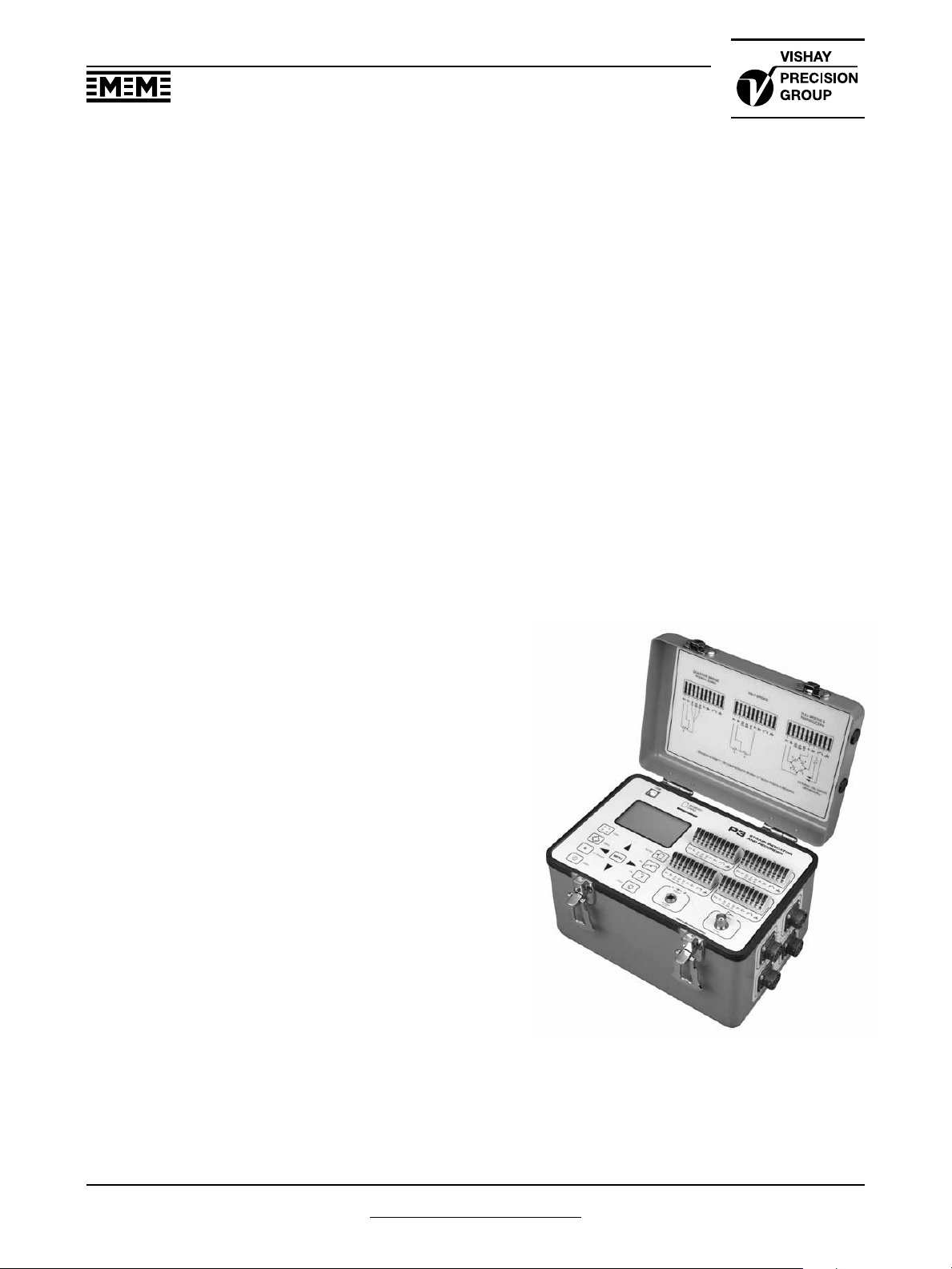
The Model P3 Strain Indicator and Recorder is a portable,
battery-operated instrument capable of simultaneously
accepting four inputs from quarter-, half-, and fullbridge strain-gage circuits, including strain-gage-based
transducers. Water-resistant grommets in the hinged
cover allow the lid to be closed with leadwires attached.
Designed for use in a wide variety of physical test and
measurement applications, the P3 functions as bridge
amplifier, static strain indicator, and digital data logger.
The Model P3 Strain Indicator and Recorder, utilizing a
large LCD display for readout of setup information and
acquired data, incorporates many unique operating
features that make it the most advanced instrument of
its kind. An extensive, easy-to-use menu-driven user
interface operates through a front-panel keypad to readily
configure the P3 to meet your particular measurement
requirements. Selections include active input and output
channels, bridge configuration, measurement units, bridge
balance, calibration method, and recording options,
among others.
Standard sensor input connection is via eccentric-leverrelease terminal blocks. Optional transducer connection
is available via side-mounted bayonet locking circular
connectors.
Data, recorded at a user-selectable rate of up to 1 reading
per channel per second, is stored on a removable flash
card and is transferred by USB to a host computer for
subsequent storage, reduction and presentation with the
supplied software.
The P3 can also be configured and operated directly from
your PC with a separate software application included
with each instrument. Additionally, a full set of ActiveX
components is provided for creating custom applications
in any language supporting ActiveX.
A highly stable measurement circuit, regulated
bridge excitation supply, and precisely settable gage
factor enable measurements of ±0.1% accuracy and
1 microstrain resolution. Bridge completion resistors of
120, 350 and 1000 ohms are built in for quarter-bridge
operation. Also, input connections and switches are
provided for remote shunt calibration of transducers and
full-bridge circuits.
The P3 operates from two readily available D cells.
Battery life depends upon mode of operation but ranges
up to 600 hours of continuous use for a single channel. It
can also be powered by connection to an external battery
or power supply, a USB port on a PC or with an optional
external line-voltage adapter, the Model P3-A105.
www.micro-measurements.com
6
For technical questions, contact
micro-measurements@vishaypg.com
Document No.: 11102
Revision: 06-May-2011
Page 2

Micro-Measurements
Strain Indicator and Recorder
P3
P3
HARDWARE SPECIFICATIONS
All specifications nominal or typical at +23°C unless
noted.
Inputs
Eccentric-lever-release terminal blocks accept up to four
independent bridge inputs. Accommodates 16-28 AWG
(1.3 to 0.35 mm diameter) wire.
The Transducer Option includes four 10-pin bayonet
locking circular connectors mounted on the side of the
case and wired in parallel to the lever-release terminal
blocks. The supplied mating connector has a 0.046 inch
(1.17 mm) diameter solder well.
Bridge Configurations
Quarter-, half-, and full-bridge circuits. Internal bridge
completion provided for 120Ω, 350Ω and 1000Ω quarter
bridges, 60 to 2000Ω half or full bridge.
Display
Full dot-matrix structure with 128 dots x 64 dots FSTN
positive, gray transflective LCD with backlight. Display
update is twice a second.
Data Conversion
High-resolution sigma-delta converter. 60 Hz or 50 Hz
noise rejection. User selectable.
Basic Range
±31,000 microstrain (±1 microstrain resolution) at Gage
Factor = 2.000
Accuracy
±0.1% of reading ±3 counts. (Normal mode operation at
Gage Factor = 2.000)
Gage Factor Settings
Range 0.500 to 9.900
Balance
Single key operation to initiate automatic software
balance
Bridge Excitation
1.5 VDC nominal. Readings are fully ratiometric, and not
degraded by variation in excitation voltage
Communication Interface
Universal Serial Bus with type B connector. Used for
transferring stored data and firmware.
Data Storage
Media: Removable Secure Digital or Multimedia Card
(2GB max).
Data Recording Rate: 1 reading per second
maximum.
Calibration
Shunt calibration across each dummy resistor to simulate
5000 microstrain (±0.1%). Remote calibration supported
via accessible switch contacts at input terminal block.
Analog Output
BNC connector. 0 to 2.5V maximum output. Device
impedance of 2000Ω or greater. 480 samples/second
DAC output update rate.
Power
Internal battery pack using two “D” cells. Battery life up
to 600 hours (single channel, normal mode.) Can also
be powered from USB or by external battery or other
power source of 6 to 15 VDC. AC adapter optional
(Model P3-A105).
Operational Environment
Temperature 0 to + 50°C. Humidity up to 90% RH,
noncondensing
Document No.: 11102
Document No.: 11102
Revision: 06-May-2011
Revision: 06-May-2011
For technical questions, contact
micro-measurements@vishaypg.com
www.micro-measurements.com
7
Page 3
P3
Micro-Measurements
Strain Indicator and Recorder
FIRMWARE FEATURES
Display Update Rate
2 readings per second
Recording Rates
Up to 64 data files
Automatic recording
1 reading every 1 to 3600 seconds
Individually selectable per channel
Manual recording
Automatic date/time stamping
Scaling
Automatic scaling for microstrain, based upon gage
factor, with nonlinearity correction based upon bridge
type
Automatic calculation of mV/V
Linear scaling for other engineering units
Units
με
mV/V lbf m deg
psi lb s rad
ksi kg A oz
GPa in N mV
MPa mm V m/s
Pa mil Ohms ton
Bridge Types
Quarter bridge
Half bridge, adjacent arms, equal and opposite strains
Half bridge opposite arms equal strains
Shear bridge, 2 active arms
Poisson half bridge
Full bridge 4 fully active arms
Shear bridge, 4 active arms
Full bridge, Poisson gages in opposite arms
Full bridge, Poisson gages in adjacent arms
Undefined full bridge
Undefined half bridge/quarter bridge
g rpm hp
2
Software Adjustable Contrast
Operating Modes
Normal mode
Analog output (any one of four channels)
Data Link
USB interface
Windows-based P3 software provided for control and
data storage
No device driver required (treated as an HID device)
Real-time Clock
System Calibration/Verification
Requires Model 1550A Strain Indicator calibrator or other
compatible calibrator
Calibration date stored in flash memory
Firmware Upgradeable
View Showing
Optional Transducer
Input Connectors
Bridge Balance
Automatic
Manual offset adjust
Disabled (Raw offset)
Backlight Control
Programmable on time while in run mode
5, 15 or 60 seconds
Manual off/on
If illuminated, backlight will remain illuminated while
operating menus
www.micro-measurements.com
8
For technical questions, contact
micro-measurements@vishaypg.com
Document No.: 11102
Revision: 06-May-2011
Page 4

Legal Disclaimer Notice
Legal Disclaimer Notice
Vishay Precision Group
Disclaimer
ALL PRODUCTS, PRODUCT SPECIFICATIONS AND DATA ARE SUBJECT TO CHANGE WITHOUT NOTICE.
Vishay Precision Group, Inc., its affiliates, agents, and employees, and all persons acting on its or their
behalf (collectively, “Vishay Precision Group”), disclaim any and all liability for any errors, inaccuracies or
incompleteness contained herein or in any other disclosure relating to any product.
The product specifications do not expand or otherwise modify Vishay Precision Group’s terms and conditions of
purchase, including but not limited to, the warranty expressed therein.
Vishay Precision Group makes no warranty, representation or guarantee other than as set forth in the terms
and conditions of purchase. To the maximum extent permitted by applicable law, Vishay Precision Group
disclaims (i) any and all liability arising out of the application or use of any product, (ii) any and all liability,
including without limitation special, consequential or incidental damages, and (iii) any and all implied
warranties, including warranties of fitness for particular purpose, non-infringement and merchantability.
Information provided in datasheets and/or specifications may vary from actual results in different applications
and performance may vary over time. Statements regarding the suitability of products for certain types of
applications are based on Vishay Precision Group’s knowledge of typical requirements that are often placed on
Vishay Precision Group products. It is the customer’s responsibility to validate that a particular product with the
properties described in the product specification is suitable for use in a particular application.
No license, express, implied, or otherwise, to any intellectual property rights is granted by this document, or by
any conduct of Vishay Precision Group.
The products shown herein are not designed for use in life-saving or life-sustaining applications unless otherwise
expressly indicated. Customers using or selling Vishay Precision Group products not expressly indicated for use
in such applications do so entirely at their own risk and agree to fully indemnify Vishay Precision Group for any
damages arising or resulting from such use or sale. Please contact authorized Vishay Precision Group personnel
to obtain written terms and conditions regarding products designed for such applications.
Product names and markings noted herein may be trademarks of their respective owners.
Document No.: 63999
Document No.: 63999
Revision: 27-Apr-11
Revision: 27-Apr-11
www.vishaypg.com
1
 Loading...