

Page 1
OptiVisor™400 Optical Time
Domain Reflectometer (OTDR)
A LANscape®Solutions Product
Applications
•Testing and troubleshooting of LAN, telco, CATV and
FTTx networks
Description
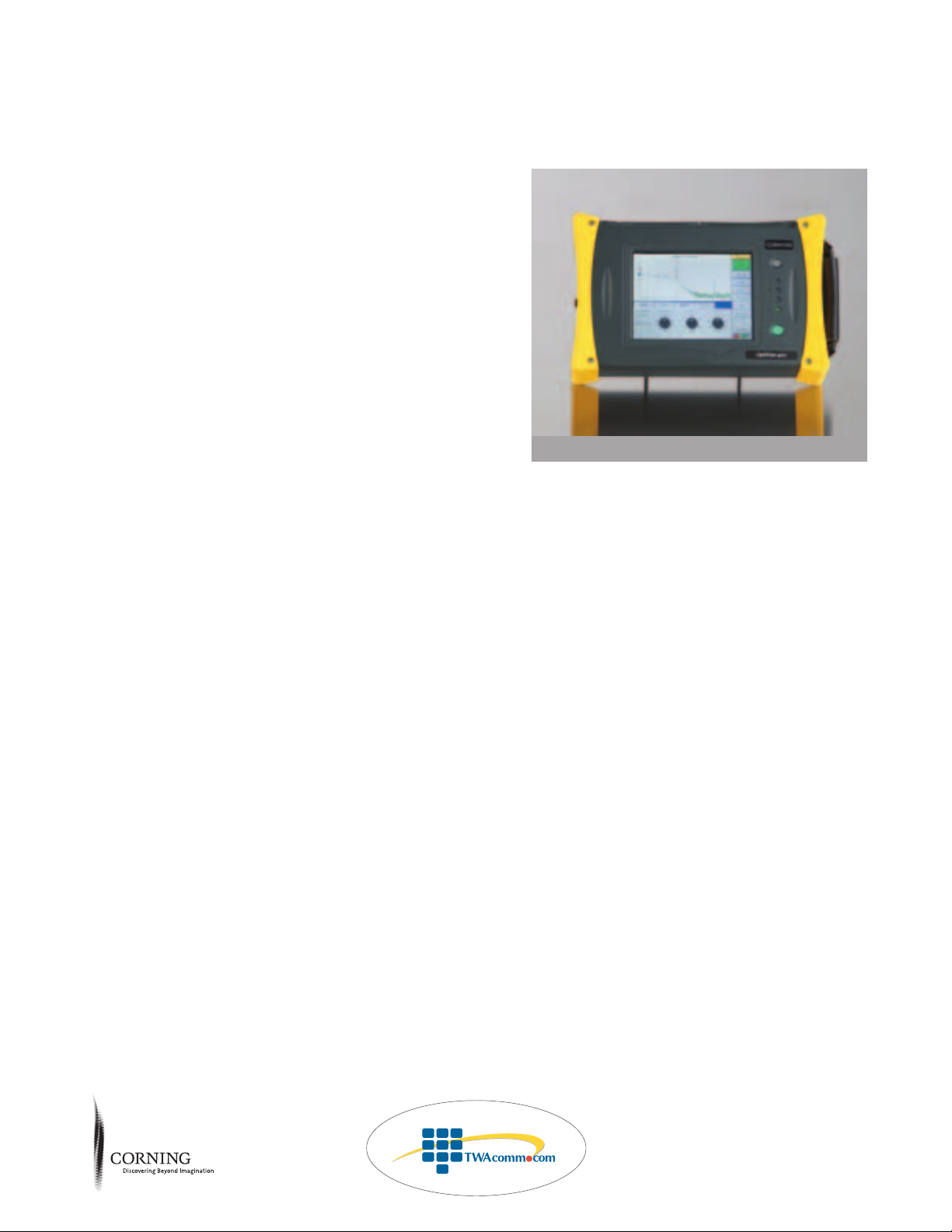
Corning Cable Systems’ OptiVisor 400 Optical Time Domain
Reflectometer (OTDR) provides testing flexibility by offering
a rugged platform with field-interchangeable multimode and
single-mode modules. All OTDR modules can be used as CW
light source and are available with an optional visual fault
locator (VFL) installed. An optional power meter is available
on the OptiVisor 400 OTDR mainframe. The standard unit
provides internal memory for storage of up to 700 traces using
Microsoft
®
Windows®CE technology, eliminating the need
for a hard drive. If extra storage capacity is needed, there is
a 1.44 MB floppy drive on the mainframe along with a
PCMCIA port.
The OptiVisor 400 OTDR product line offers a wide variety
of multimode and single-mode modules including a tri-wavelength single-mode module perfect for FTTx testing. Modules
can be easily switched out in the field, without the use of
tools, in just a matter of seconds.
The OTDR features a 7.7-inch high-quality color LCD touch
screen that is resistant to most common chemicals used in the
field. The screen is large enough to view both the trace and
the event table, thereby eliminating the need to toggle back
and forth between the two.
With three testing modes, the OptiVisor 400 OTDR offers
something for every installer. Auto Mode allows the user to
select the parameters automatically, making it perfect for basic
OTDR applications or the occasional user. Advanced Mode
offers more setup and measurement capabilities for the experienced OTDR user. Template Trace Mode allows the user to
create a template for comparison with other traces, ideal for
quick testing of multiple fibers.
Features / Benefits
• Rugged, splash-proof mainframe
•Three operating modes: Auto, Advanced, Template Trace
Corning
Cable Systems
Product Specifications
OptiVisor 400 OTD R | LAN637
•7.7-in color LCD touchscreen
•FTTx ready
•CW light source standard on all OTDR
modules
•OTSView software for report generation
•Modules available with shortest event dead zone
in the industry: 1 meter with 5 ns pulse width
•Fast testing with full averaging in as little as 45
seconds; four times faster than industry standard
•AC and battery operation
•Sample points of up to 128,000 resulting in
better trace resolution
Sold by:
http://www.TWAcomm.com
Toll Free: (877) 892-2666
Page 2

OptiVisor™400 Optical Time
Domain Reflectometer (OTDR)
A LANscape®Solutions Product
Corning
Cable Systems
Specifications
400 OTDR Main Frame
Parameter Specification
Processor Intel®StrongARM, 206 MHz
Interfaces Serial RS-232C; Parallel Printer
External Keyboard PS/2; PCMCIA Type II
Internal Memory
1
32 MB total (700 traces typ.), standard
Additional Storage (optional) PCMCIA flash cards, up to 6000 traces
Floppy Drive 3.5 inch floppy drive, 1.44 MB
Display Color LCD touchscreen, 19.6 cm (7.7 in), 640 x 480, 256 colors
Touchscreen Resistive, 8 wires; positional accuracy better than 2%, full scale,
worst-case error ≤± 0.5 cm (0.18 in); resistant to most common chemicals
2
External Power Supply AC input: 100 to 240 V, 50 Hz to 60 Hz
Battery Nickel metal-hydride (NiMH), rechargeable, smart
Battery Operating Time
3
8 h - NiMH battery
RechargeTime 2.5 h (off), 8 h (on)
Size (H x W x D) 21.6 x 33.6 x 8.9 cm (8.5 x 13.25 x 3.5 in)
Weight
4
3.7 kg (8.1 lb)
Operating Temperature
5
-5º to 50ºC (23º to 122ºF)
Storage Temperature
6
-40º to 60ºC (-40º to 140ºF), Shipping
-20º to 50ºC (-4º to 122ºF), Long Term
Relative Humidity 0% to 95% max., non-condensing
Power Meter
Detector InGaAs
Calibrated Wavelengths (nm) 850, 1300, 1310, 1550, 1625
Power Range (dBm) 4 to -70
Uncertainty (%) ±0.05 (0 dBm to -46 dBm)
Linearity (dB) ±0.05 (0 dBm to -46 dBm); ±0.1 (-46 dBm to -57 dBm)
Display Resolution (dB) 0.01 (4 dBm to -63 dBm); 0.1 (-63 dBm to -70 dBm)
Tone Detection (Hz) 270/1000/2000
Notes:
1
With GC language option, total storage is 550 traces (typical).
2
Heptane, ethanol, isopropanol, acetone, methyl ethyl ketone, cellosolve acetate, toluene, carbitol acetate, hydrochloric acid, turpentine, Vm and naphta, unleaded
gasoline, motor oil, diesel fuel, transmission fluid, antifreeze.
3
According to Telcordia TR-NWT-001138, with monochrome display.
4
OptiVisor 400 with OTDR module and battery.
5
Excluding floppy drive (use is not recommended below 0ºC). OTDR module performance can be affected at sub-zero temperatures.
6
Excluding the battery.
Sold by:
http://www.TWAcomm.com
Toll Free: (877) 892-2666
Page 3

OptiVisor™400 Optical Time
Domain Reflectometer (OTDR)
A LANscape®Solutions Product
Specifications
Multimode Module
1
Dynamic Range
2
Event Dead Attenuation
Model Wavelength (nm) at 100 ns/1µs (dB) Zone3(m) Dead Zone3(m)
400-MD25-XX
4
850 ± 20/1300 ± 20 23/27 1.5/1.5 5/5
Single-mode Module
1
Dynamic Range2Dynamic Range2Event Dead Attenuation
Model Wavelength (nm) at 10 µs (dB) at 20 µs (dB) Zone5(m) Dead Zone5(m)
400-SD34-YY 1310 ± 20/1550 ± 20 35/34 36/35 1/1 5/6 (4/4)
6
400-SD37-YY 1310 ± 20/1550 ± 20 38/37 39/38 1/1 5/6 (4/4)
6
400-SD135-YY 1550 ± 20/1625 ± 10 37/35 38/36 1/1 6/6 (4/5)
6
400-ST37-YY 1310 ± 20/1550 ± 20/1625 ± 10 38/37/35 39/38/36 1/1/1 5/6/6 (4/4/5)
6
400-ST137-YY 1310 ± 20/1490 ± 10/1550 ± 20 38/34/37 39/35/38 1/1/1 5/6/6 (4/4/4)
6
400-SD40-YY 1310 ± 20/1550 ± 20 40/40
10
41.5/40.5
10
3/3 10/15
400-SD140-YY 1550 ± 20/1625 ± 10 4010/38 40.510/39 3/3 15/16
400-SD45-YY
7
1310 ± 20/1550 ± 20 43.5/43.5
11
45/45
11
3/3 10/15
400-SD142-YY
7
1550 ± 20/1625 ± 10 43.511/41.5 4511/43 3/3 15/16
400-ST41-YY 1310 ± 20/1550 ± 20/1625 ± 10 41/40/38 42.5/41.5/39.5 3/3/3 8/10/10
400-SD34/ 400-SD40/SD140/SD45/
General Specifications 400-MD25 SD37/SD135/ST37/ST137 SD142/ST41
Distance Range (km) 0.625, 1.25, 2.5, 5, 10, 1.25, 2.5, 5, 10, 20, 40, 1.25, 2.5, 5, 10, 20, 40, 80,
20, 40 80, 160, 260 160, 260
Pulse Width (ns) 10, 30, 100 (850 nm) 5, 10, 30, 100, 275, 1000, 10, 30, 100, 275, 1000,
10, 30, 100, 275, 1000 (1300 nm) 2500, 10,000, 20,000 2500, 10,000, 20,000
Linearity (dB/dB) ±0.05 ±0.03 ± 0.05
Loss Threshold (dB) 0.01 0.01 0.01
Loss Resolution (dB) 0.001 0.001 0.001
Sampling Resolution (m) 0.08 to 5 0.04 to 5 0.08 to 5
Sampling Points Up to 16,000 Up to 128,000 Up to 52,000
Distance Uncertainty8(m) ± (1 + 0.0025 % x distance) ± (0.75 + 0.0025 % x distance) ± (1 + 0.0025 % x distance)
Measurement Time User-defined User-defined User-defined
(60 min. maximum) (60 min. maximum) (60 min. maximum)
Real-time Refresh (s) ≤ 1Guaranteed: ≤ 0.4 ≤ 1
Ty pical: ≤ 0.3
Stable Source Output Power9 (dBm) -7 -8 (400-SD34); -4.5 (all others) -5
Visual Fault Locator (optional) Laser, 650 nm ± 10 nm Laser, 650 nm ± 10 nm Laser, 650 nm ± 10 nm
CW, P
out
maximum: ≤ 800 µW CW, P
out
maximum: ≤ 5 µW CW, P
out
maximum: ≤ 800 µW
Notes:
1
All specifications valid at 23ºC ± 2ºC (73.4ºF ± 3.6 oF) with an FC/PC connector, unless otherwise specified.
2
Typical dynamic range with a three-minute averaging at SNR = 1 (for 400-SD34/SD37/SD135/ST37/ST137, typical dynamic range
with 45-second averaging is only 1 dB lower than values given for three-minute averaging).
3
Ty pical dead zone of multimode modules for reflectance below -35 dB using a 10 ns pulse.
4
ORL measurement not available for this module.
5
Ty pical dead zone of single-mode modules for reflectance below -45 dB, using a 10 ns pulse (5 ns pulse for 400-SD34/SD37/SD135/ST37/ST137).
6
Typical dead zone of 400-SD34/SD37/SD135/ST37/ST137 single-mode modules for reflectance below -55 dB, using a 5 ns pulse.
7
Typical dynamic range on NZDS fiber with a three-minute average at SNR = 1.
8
Does not include uncertainty due to fiber index and sampling resolution.
9
Ty pical output power value at 1550 nm.
10
Ty pical dynamic range at 1550 nm for the 400-SD40 configuration is 2 dB lower at 10 µs and 1 dB lower at 20 µs.
11
Ty pical dynamic range at 1550 nm for the 400-SD45 configuration is 2 dB lower.
Corning
Cable Systems
Sold by:
http://www.TWAcomm.com
Toll Free: (877) 892-2666
Page 4

OptiVisor™400 Optical Time
Domain Reflectometer (OTDR)
A LANscape®Solutions Product
Corning
Cable Systems
Ordering Information
Basic Kits
Kits include OptiVisor 400 Mainframe, single-mode and/or multimode module, power supply, Smart NiMH battery,
9 volt battery, RS232 serial cable, CD with OTSView PC emulation software and user’s manual, cleaning supplies,
Quick Reference manual, and hard-shell transit case.
Part Number Description
400BK-SD34-YY Short-range dual single-mode (35/34 dB)
400BK-SD37-YY Mid-range dual single-mode (38/37 dB)
400BK-ST37-YY Mid-range triple single-mode 1310/1550/1625 nm (38/37/35 dB)
400BK-ST137-YY FTTx SM 1310/1490/1550 nm (38/34/37 dB)
400BK-SD40-YY Long-range dual single-mode (40/40 dB)
400BK-SD45-YY Extended-range dual single-mode (43.5/43.5 dB)
400BK-MD25-XX Dual multimode (23/27 dB)
400BK-MDSD-XX-YY Dual multimode (23/27 dB) and single-mode (35/34 dB)
Deluxe Kits
Kits include OptiVisor 400 OTDR Mainframe with power
meter, single-mode and/or multimode module with VFL,
power supply, Smart NiMH battery, 9 volt battery, RS232 serial
cable, CD with OTSView PC emulation software, OTSBatch
PC batch processing software and user’s manual, cleaning supplies,
Quick Reference manual, and hard-shell transit case.
Part Number Description
400DK-SD34-YY Short-range dual single-mode (35/34 dB)
400DK-SD37-YY Mid-range dual single-mode (38/37 dB)
400DK-ST37-YY Mid-range triple single-mode 1310/1550/1625 nm (38/37/35 dB)
400DK-ST137-YY FTTx SM 1310/1490/1550 nm (38/34/37 dB)
400DK-SD40-YY Long-range dual single-mode (40/40 dB)
400DK-SD45-YY Extended-range dual single-mode (43.5/43.5 dB)
400DK-MD25-XX Dual multimode (23/27 dB)
400DK-MDSD-XX-YY Dual multimode (23/27 dB) and single-mode (35/34 dB)
Adapter Codes
XX = MM port SC = SC, FC = FC, ST = ST®compatible
YY = SM port SC = SC, FC = FC, ST = ST compatible
OptiVisor 400 OTDR Basic Kit | LAN638
Sold by:
http://www.TWAcomm.com
Toll Free: (877) 892-2666
Page 5

OptiVisor™400 Optical Time
Domain Reflectometer (OTDR)
A LANscape®Solutions Product
Corning
Cable Systems
Ordering Information
Mainframes
Standard components on mainframes include: PCMCIA port, RS232 port, 7.7 inch color touch screen, and floppy
drive.
Part Number Description
400-MAINF-STD OTDR Controller, with 3.5 in floppy drive
400-MAINF-PM OTDR Controller, with 3.5 in floppy drive and Power Meter
OptiVisor 400 OTDR Modules
Part Number Description
400-MD25-XX Multimode OTDR Module, 850/1300 nm (23/27 dB)
400-SD34-YY Single-mode Short-Range OTDR Module, 1310/1550 nm (35/34 dB)
400-SD37-YY Single-mode Mid-Range OTDR Module, 1310/1550 nm (38/37 dB)
400-SD135-YY Single-mode Mid-Range OTDR Module, 1550/1625 nm (37/35 dB)
400-ST37-YY Single-mode Mid-Range OTDR Module, 1310/1550/1625 nm (38/37/35 dB)
400-ST137-YY Single-mode Mid-Range OTDR Module, 1310/1490/1550 nm (38/34/37 dB)
400-SD40-YY Single-mode Long-Range OTDR Module, 1310/1550 nm (40/40 dB)
400-SD140-YY Single-mode Long-Range OTDR Module, 1550/1625 nm (40/38 dB)
400-SD45-YY Single-mode Extended-Range OTDR Module, 1310/1550 nm (43.5/43.5 dB)
400-SD142-YY Single-mode Extended-Range OTDR Module, 1550/1625 nm (43.5/41.5 dB)
400-ST41-YY Single-mode Long-Range OTDR Module, 1310/1550/1625 nm (41/40/38 dB)
400-MDSD-XX-YY Multimode/Single-mode Quad OTDR Module, 850/1300/1310/1550 nm (26/25/35/34 dB)
-VFL (add before connector code) VFL option for above modules, example: 400-SD34-VFL-YY
Adapter Codes
XX = MM port SC = SC, FC = FC, ST = ST®compatible
YY = SM port SC = SC, FC = FC, ST = ST compatible
Sold by:
http://www.TWAcomm.com
Toll Free: (877) 892-2666
Page 6

OptiVisor™400 Optical Time
Domain Reflectometer (OTDR)
A LANscape®Solutions Product
Corning
Cable Systems
Corning Cable Systems LLC • PO Box 489 • Hickory, NC 28603-0489 USA
1-800-743-2675 • FAX: +1-828-901-5973 • International: +1-828-901-5000 • http://www.corning.com/cablesystems
Corning Cable Systems reserves the right to improve, enhance,and modify the features and specifications of Corning Cable Systems’products
without prior notification. LANscape is a registered trademark of Corning Cable Systems Brands, Inc. OptiVisor is a trademark of Corning Cable
Systems Brands, Inc. Discovering Beyond Imagination is a trademark of Corning Incorporated. All other trademarks are the properties of their
respective owners. Corning Cable Systems is ISO 9001 certified.© 2005 Corning Cable Systems. All rights reserved. Published in the USA.
LAN-634-EN / February 2005 / pdf
Accessories
Part Number Description
UI-SC Universal Interface Source Connector Adapter, SC
UI-ST Universal Interface Source Connector Adapter, ST
UI-FC Universal Interface Source Connector Adapter, FC
OA-SC Power Meter Connector Adapter, SC
OA-ST Power Meter Connector Adapter, ST
OA-FC Power Meter Connector Adapter, FC
OA-LC Power Meter Connector Adapter, LC
OTSBATCH PC Batch processing software
CASE-OV-400 Hardshell transit case with wheels
USB-OV-400 PCMCIA to USB Data Transfer Kit with 256 MB SD card
PS-18-1660 Power supply for 100-240 V AC with US line card
OTDR Launch Cables*
Part Number Description
Multimode, Single Fiber
PTF-100M-XPYYZZ Portable Test Fiber, 100 meters in length, multimode fiber
Fiber Type (X) 6 = Standard 62.5 µm, C = Standard 50 µm, 5 = Laser Optimized 50 µm
Connector Code (YY) 39 = SC, 50 =ST®compatible, 17 = FC, 03 = LC
Connector Code (ZZ) 39 = SC, 50 = ST compatible, 17 = FC, 03 = LC
Single-mode, Single Fiber
PTF-300M-SPYYZZ Portable Test Fiber, 300 meters in length, standard single-mode fiber
Connector Code (YY) 58 = SC, 61 = ST compatible, 54 = FC
Connector Code (ZZ) 58 = SC, 61 = ST compatible, 54 = FC
* Recommended configurations; please contact customer service for other configurations.
Sold by:
http://www.TWAcomm.com
Toll Free: (877) 892-2666
 Loading...