

Page 1
MULTITECHNOLOGY FLAW DETECTOR: UT, PA, EC, ECA
OmniScan® MX
• Portability
• Modularity
• Color Imaging
• Data Storage
920-117H-EN
Page 2
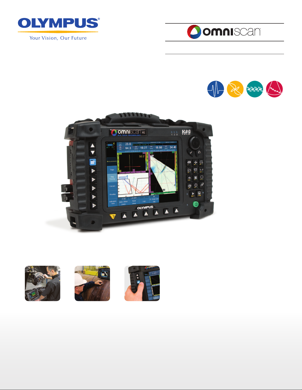
OmniScan® MX
With thousands of units being used
throughout the world, the OmniScan MX is
Olympus NDT’s most successful portable
and modular phased array and eddy current
array test instrument. The OmniScan family
includes the innovative phased array and
eddy current array test modules, as well as
the conventional eddy current and ultrasound modules, all designed to meet the
most demanding NDT requirements. The
OmniScan MX offers a high acquisition
rate and powerful software features—in a
portable, modular instrument—to efficiently
perform manual and automated inspections.
Rugged, Portable, and
Battery Operated
The OmniScan is built to work in the harshest field conditions. A solid polycarbonatebased casing and rubber bumpers make it a
rugged instrument capable of withstanding
drops and shocks.
The OmniScan is so compact and lightweight (only 4.6 kg, 10.1lb) that it can
be carried easily and handled anywhere,
inside or outside. The OmniScan will run
for 6 hours with its two Li-ion batteries.
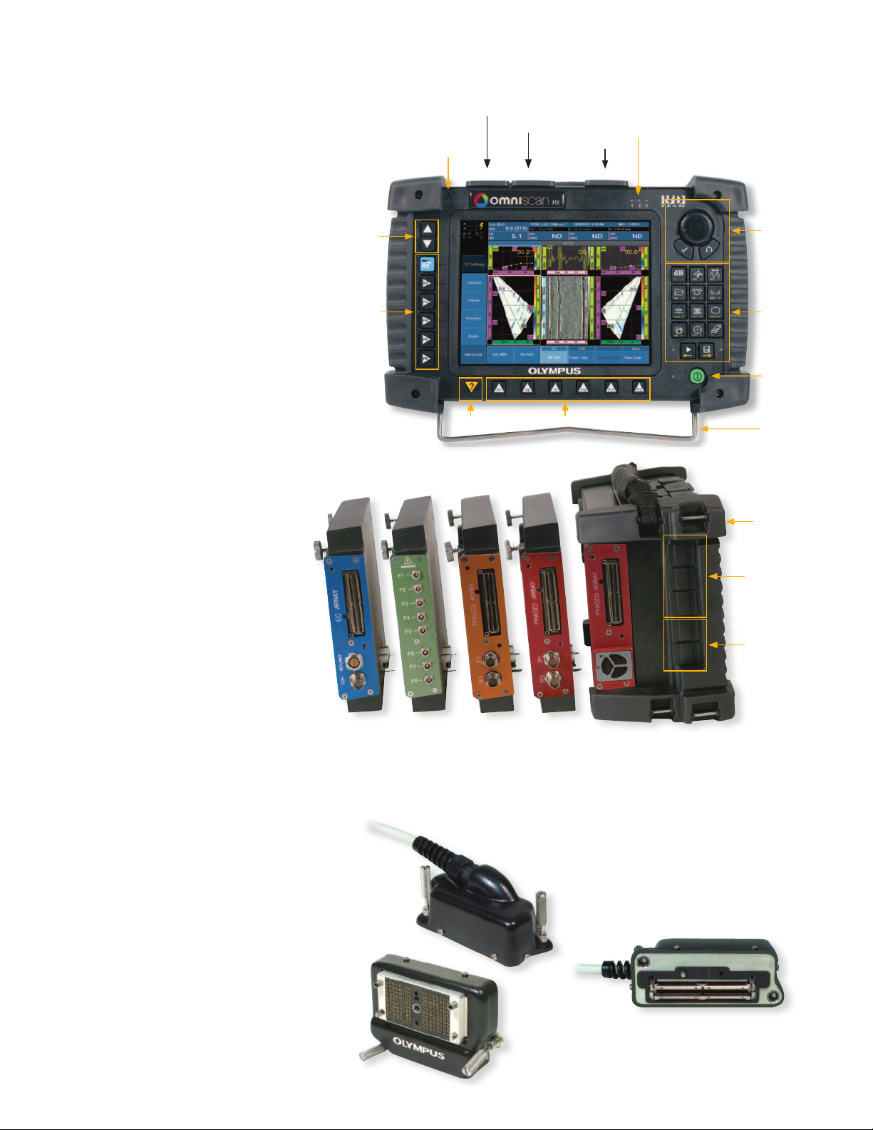
Up/Down keys
Menu keys
Scanner interface
Microphone
Help key Parameter keys
Alarm indicator LEDs
SVGA output
Alarm and I/O
Control area
Function keys
On/off switch
Tilt stand
Protective bumpers
User Interface
The highly legible 8.4-inch real-time
display (60-Hz A-scan refresh rate) with an
SVGA resolution of 800 x 600 allows you
to clearly see defects and details under any
light conditions. A scroll knob and function
keys make it easy to browse through and
select functions. A mouse and keyboard
can also be connected for users looking for
a more PC-like interface.
Modular Instrument
The instrument allows you to switch between its different test modules on location.
When a new module is connected, the
instrument detects the module and its supported technology so that the configuration
and test environment are set automatically.
OmniScan Connector
The OmniScan connector has a probe ID
feature that enables physical detection and
recognition of the probe connected to the
instrument.
• Sets the probe to an appropriate
frequency to prevent probe damage.
• Sets C-scan resolution for ECA probes.
• Loads the correct probe parameters.
Eddy current
array module
8-channel
UT module
16:16M
phased array
module
16:128
phased array
module
USB connectors
• Keyboard
• Mouse
• Printer
Ethernet
and serial ports
32:128
phased array
module
Adapters able to connect to probes from other
manufacturers are available.
2
www.olympus-ims.com
Page 3
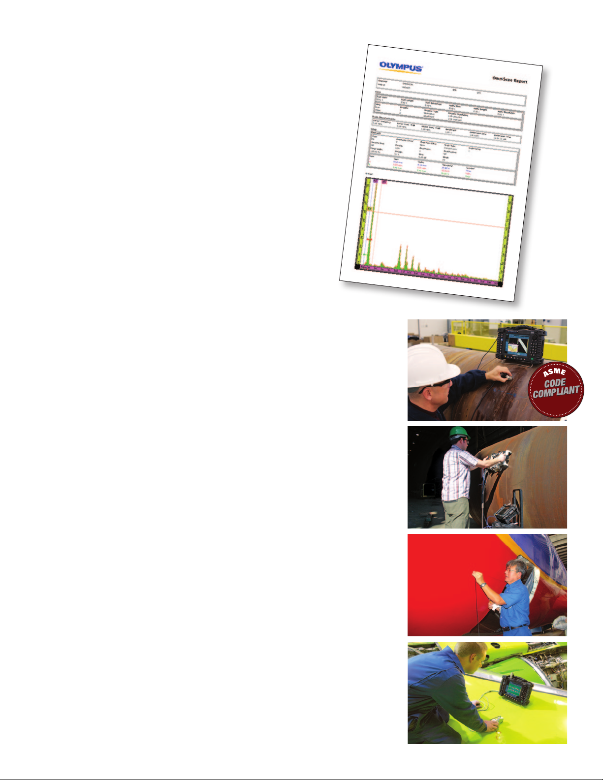
Setup and Reporting
• Setup storage is compatible with Microsoft Windows
(exportable using a CompactFlash card).
• Complete report setups, including reading configurations, that
can be customized using HTML page layouts.
• Easy report generation, from acquired data to complete report
in seconds
• On-screen interactive help that can be customized for
procedure-oriented setups using HTML script templates
• Setup preview
• Predefined setups
Connectivity, Data Storage, and Imaging
The OmniScan® offers alarm outputs and standard PC ports: USB,
SVGA out, and Ethernet. It offers internal data storage capability
and extended storage via a CF (CompactFlash) card slot as well as
any USB or network storage.
Typical Applications
Girth Weld Inspection
Olympus NDT developed a circumferential weld inspection system for the oil and gas
industry based on the OmniScan PA. This phased array system is qualified to inspect tubes
with diameters ranging from 48 mm to 1524 mm and thicknesses from 5 mm to 25 mm in
compliance with the ASME Boiler and Pressure Vessel Code, Section V. The semiautomated
system offers better inspection speed and detection, and makes interpretation of the indications significantly easier.
Pressure Vessel Weld Inspection
The combination of time-of-flight diffraction (TOFD) and pulse-echo techniques means
that a complete inspection can be performed in a single scan, significantly reducing the
inspection time when compared to conventional raster scanning or radiography. Inspection results are instantly available, allowing you to find problems with the welding equipment and fix it right away. Based on our vast experience in the nuclear and petrochemical
industries, this system includes all the functions that are needed for code-compliant weld
inspections.
Scribe Marks Inspection with No Paint Removal
The Flight Standards Information Bulletin for Airworthiness (FSAW 03-10B), issued in No-
vember 2003, reports damage along fuselage skin lap joints, butt joints, and other areas of
several aircraft caused by the use of sharp tools used during paint and sealant removal.
The OmniScan allows scribe marks inspections to be performed without paint removal,
which is a huge time-saver. The inspections are performed in a single pass using 60º to 85º
SW sectorial scans. The OmniScan PA is now referenced in the Boeing NTM manuals, 737
NDT Manual, Part 4, 53-30-06, July 2005.
Aircraft Fuselage Inspection
The OmniScan ECA (eddy current array) provides the ability to detect hidden corrosion
and cracks in multilayer structures. Currently, material loss of 10% of the lap-splice thickness can be detected in aluminum at a depth of 5 mm. Surface and subsurface cracks can
be detected in the skin, at the fastener, or at the lap-joint edges.
3
Page 4
Ultrasound Inspection
Transmitter Receiver
Lower tip
Upper tip
Backwall (+) Lower tip (+) Upper tip (+) Lateral waves (+)
Lateral waves
Backwall reflection
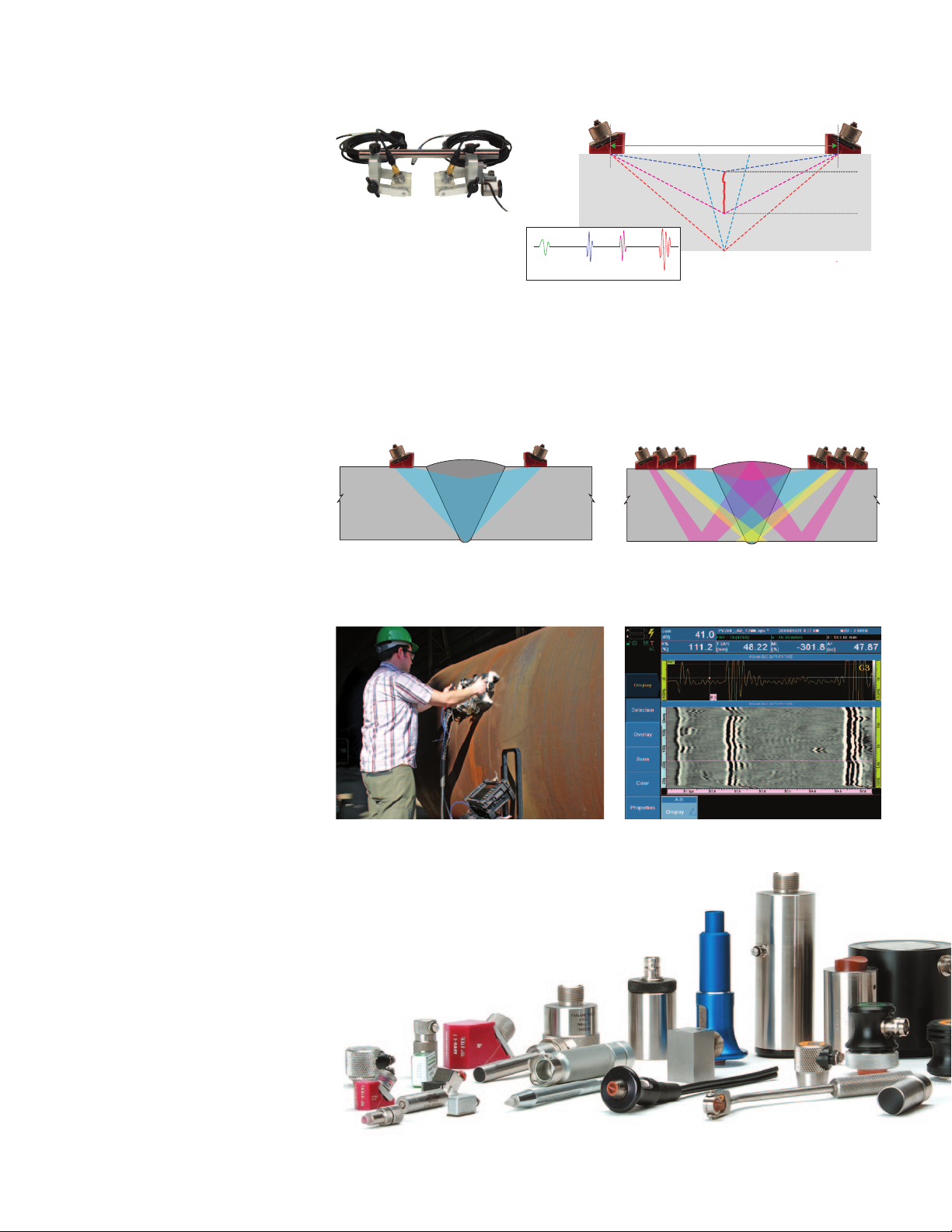
Time-of-Flight Diffraction Testing
Time-of-flight diffraction (TOFD) is a
technique that uses two probes in pitchcatch mode. TOFD detects and records
signals diffracted from defect tips allowing
both detection and sizing. The TOFD data
is displayed in a grayscale B-scan view.
TOFD offers wide coverage and amplitudeindependent sizing complying with the
ASME-2235 code.
• One-line scan for full-volume inspection
• Setup independent of weld configuration
• Very sensitive to all kinds of defects and
unaffected by defect orientation
TOFD and Pulse-Echo Testing
While TOFD is a very powerful and efficient technique, its coverage is limited as
a result of two inspection dead zones: one
dead zone is near the surface, the other is
at the backwall.
The OmniScan® UT allows inspections that
simultaneously combine TOFD with conventional pulse echo. Pulse echo complements TOFD, covering the dead zones.
• TOFD inspection
• 45º pulse echo for weld cap inspection
on either side of the weld
• 60º pulse echo for weld root inspection
on either side of the weld
0-Degree Testing
(Corrosion and Composite)
0-degree testing measures the time-of-flight
and amplitude of ultrasonic echoes reflecting from the part into gates in order to
detect and measure defects.
• C-scan imaging
• Full A-scan recording with C-scan
postprocessing
Ultrasound Transducers
Olympus NDT offers a selection of thousands of transducers in standard frequencies, element diameters, and connector
styles.
• Contact and immersion transducers
• Dual transducers
• Angle-beam transducers and wedges
• Replaceable delay line transducers
• Protected face transducers
• Normal incidence shear-wave
transducers
Transmitter Receiver
Lateral waves
Upper tip
The TOFD hand scanner is a small, lightweight, efficient, low-cost, and versatile
weld inspection solution.
It can accommodate a full range of probes
and wedges, including the CentraScan™
composite product line.
Weld inspection using TOFD. Weld inspection using combined TOFD and pulse echo
HSMT-Flex scanner used for TOFD applications (PV-100).
General view of TOFD setup for linear weld inspection showing
lateral wave, backwall echo, and diffracted signals on the A-scan.
TOFD
60º SW
45º SW
Transmit
PE
PE
(PV-100).
Weld inspection with TOFD.
Lower tip
Backwall reflection
TOFD
Receive
60º SW
45º SW
PE
PE
4
www.olympus-ims.com
Page 5
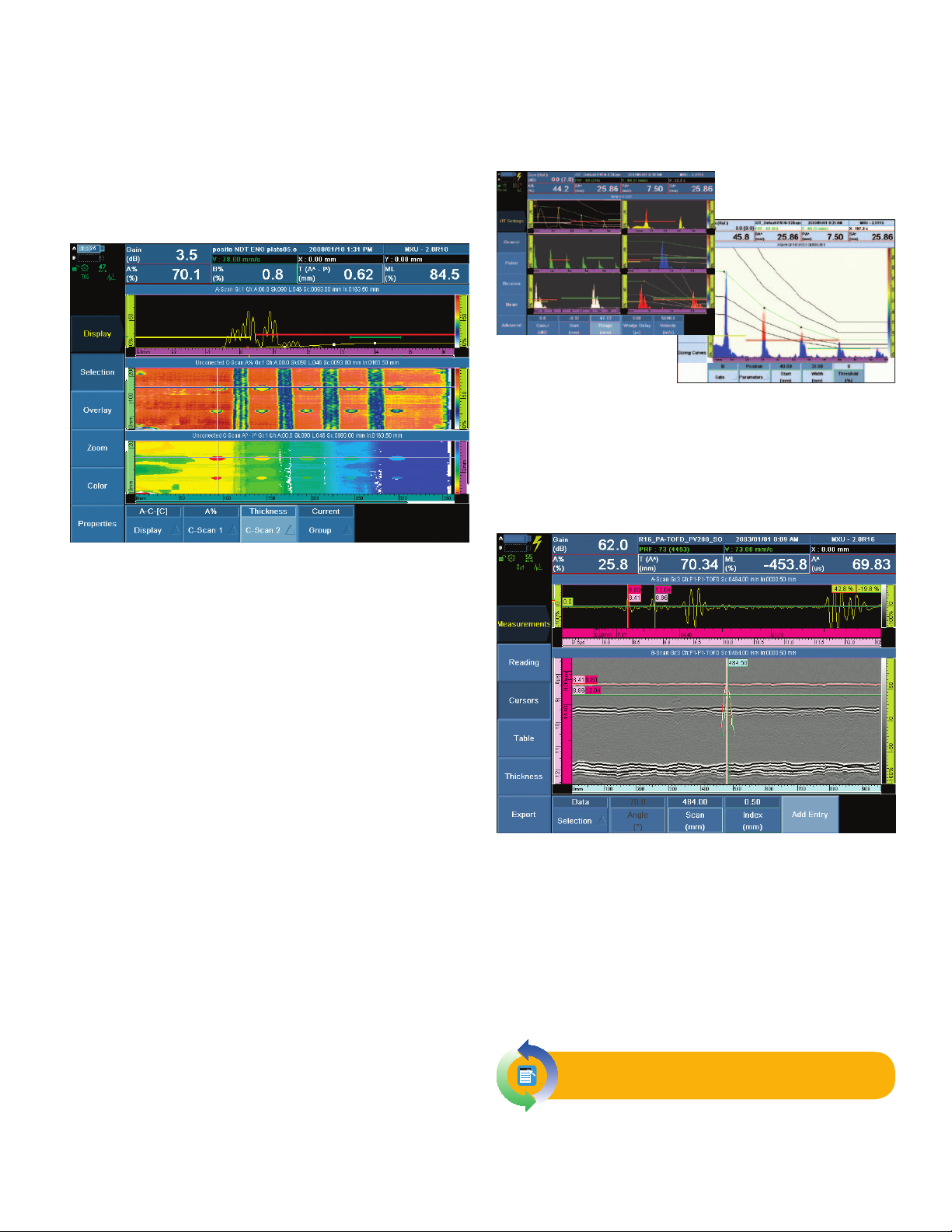
Ultrasound Software
Full-Featured C-Scan
• Monitors amplitude, peak position, crossing level position,
and thickness on each gate.
• Automatic gate synchronizes from previous gate for higher
dynamic range of thickness.
• A-scan data storage and C-scan postprocessing capabilities
Step-by-Step Calibration Wizards
All calibration procedures are guided using step-by-step wizards.
Multiple A-scan display.
Indoor/outdoor color schemes for
improved readability in all conditions.
• Sound velocity calibration
• Wedge delay calibration
• TOFD calibration
• TCG calibration
• Encoder calibration
TOFD Option
• Optional IF gate for surface-following synchronization or
measurement gate, or TCG/DAC curves
• Positive or negative gate on RF signal (independent for each
gate)
• Eight completely configurable alarms on single-gate events
or multiple-gate events, filter for n occurrences from one or
multiple channels
• Customizable color palette for amplitude and thickness
C-scans
• Adjustable 256-level color palette
• 2-axis mechanical encoding with data-acquisition
synchronization on mechanical movement
• Optional data library to access A-scans and/or C-scans on PCs
for custom processing
Full-Featured B-Scan
• Easy-to-interpret cross-sectional view of inspected part
• Excellent display of corrosion mapping for boilers, pipes, and
storage tanks
• Visual identification of acquired thickness values
• Encoded TOFD capability for amplitude-independant defect
sizing
Full-Featured A-Scan
• Color-selectable A-scan display
• Reject mode
• Hollow mode
• Peak-hold mode (always keeps the signal that shows the
maximum amplitude in gate A)
• Gate threshold-level crossing (changes the color of the curve
that is over the gate level)
• 60 Hz A-scan refresh rate with overlays of envelope and peak
inside the gate
• B-scan encoded data imaging and storage
• Grayscale color palette, adjustable for brightness and contrast
• 100 MHz A-scan digitizing
• TOFD calibration wizard, online and offline
• Hyperbolic cursor and reading for TOFD sizing
• Lateral wave resynchronization
Live switching between conventional
UT and phased array UT
5
Page 6

Transmitting
delays
Receiving delays
and sum
Probe elements
Pulses
Incident wave front
Reflected wave front
Trigger
Flaw
Flaw
Echo signals
Emitting
Acquisition unit
Receiving
Phased array unit
Phased Array Inspection
Phased Array Technology
Phased array technology enables the
generation of an ultrasonic beam where
parameters such as angle, focal distance, and focal point size are controlled
through software. Furthermore, this beam
can be multiplexed over a large array.
These capabilities open a series of new
possibilities. For instance, it is possible to
quickly vary the angle of the beam to scan
a part without moving the probe itself.
Phased arrays also allow replacing multiple probes and mechanical components.
Inspecting a part with a variable-angle
beam also maximizes detection regardless
of the defect orientation, while optimizing
signal-to-noise ratio.
Benefits of Phased Arrays
Phased array technology offers the following benefits:
• Software control of beam angle, focal
distance, and spot size
• Multiple-angle inspection with a
single, small, electronically-controlled
multielement probe
• Greater flexibility for the inspection of
complex geometry
• High-speed scans with no moving
parts
To generate a beam, the various probe elements are pulsed at slightly different times. By precisely controlling the delays between
the probe elements, beams of various angles, focal distances, and focal spot sizes can be produced. The echo from the desired
focal point hits the various transducer elements with a computable time shift. The signals received at each transducer element
are time-shifted before being summed together.
Multiple-angle inspection with one multielement probe.
Wedge and
phased array
probe
11 angles
Greater flexibility for the inspection of complex geometry.
Phased Array Probes
Olympus standard phased array probes are
divided into three categories:
• Angle beam probes with external
wedges (1) (2)
• Angle beam probes with integrated
wedge (3)
• Immersion probes (4)
Numerous accessories, such as encoders (5)
are also available.
6
The use of phased array probes enables one-line scanning
and eliminates one axis of a two-axis scan.
Active group
16
1
Scanning direction
High-speed scans with no moving parts.
Compared to a wide, single-element transducer, phased
array technology offers a much higher sensitivity due to the
use of a small focused beam.
4
1
3
2
128
5
www.olympus-ims.com
Page 7

Phased Array Software
Full-Featured A-Scans, B-Scans, and C-Scans
B-scan display
A-scan and C-scan displays
The OmniScan® PA builds upon the OmniScan UT feature set and
offers full-featured A-scan, B-scan, and C-scan displays.
Full-Featured Sectorial Scan
Wizards for Groups and Focal Laws
• The Group Wizard allows you to enter all probe, part, and
beam parameters, and generate all focal laws in one step
instead of generating them with each change.
Examples of the Focal Law Wizard
• The step-by-step approach prevents the user from missing a
parameter change.
• Online help provides general information on parameters to be
set.
Multiple-Group Option
It is now possible to manage more than one probe with two different configurations: different skews, different scanning types,
different inspection areas, and other parameters.
Sectorial scan display
Real-time data processing
• Real-time volume-corrected representation
• Higher than 20 Hz refresh rate (up to 40 Hz)
Advanced Real-Time Data Processing
• Real-time data interpolation to improve spatial representation
of defects during acquisition of data
• User-selectable high-pass and low-pass filters to enhance
A-scan and imaging quality
• Projection feature allows the operator to view vertically
positioned A-scan simultaneously with sectorial scan image.
Calibration Procedures and Parameters
All calibration procedures are guided by a step-by-step menu
using Next and Back navigation.
Possible Configurations for Multiple-Group Inspection
A Use one single phased array probe of 64 or more elements and
create 2 different groups:
Linear scan at 45º to cover the upper part
using skips on the bottom surface
Linear scan at 60º to cover the lower part
B Use one single phased array probe of 64 or 128 elements and
create 2 different groups:
Linear scan at 0º at low gain
Linear scan at 0º at higher gain
C Use one phased array probe of 64 or 128 elements and create
3 different groups:
Linear scan at 45º to cover the upper part
using skips on the bottom surface
Linear scan at 60º to cover the lower part
Sectorial scan from 35º to 70º to increase
probability of detection
D Use two phased array probes of 16 or 64 elements and create 2
different groups:
Sectorial scan from 35º to 70º for inspec-
tion from left side of the part using skips
on the bottom surface
Sectorial scan from 35º to 70º for inspec-
tion from right side of the part using skips
on the bottom surface
Example of sensitivity
calibration
7
Page 8

Eddy Current Inspection
Eddy Current Technology
Eddy current testing (ECT) is a method for
the inspection of metallic parts. The probe,
excited with an alternating current, induces
an eddy current in the part being inspected.
Any discontinuities or material property
variations that change the eddy current flow
in the part are detected by the probe as a
potential defect.
Over the years, probe technology and data
processing have continuously progressed
so that the eddy current technique is now
recognized to be fast, simple, and accurate.
This is why the technique is widely used in
the aerospace, automotive, petrochemical,
and power generation industries in the detection of surface or near-surface defects in
materials such as aluminum, stainless steel,
copper, titanium, brass, Inconel, and even
carbon steel (surface defect only).
Benefits of Eddy Currents
Eddy currents offers the following benefits:
• A quick, simple, and reliable inspection
technique to detect surface and nearsurface defects in conductive materials
• Can be used to measure the electrical
conductivity of materials.
• Measurement of nonconductive
coatings
• Hole inspection with the use of a high-
speed rotating scanner and surface
probe
Eddy Current Probes
Olympus NDT standard eddy current
probes are available in different configurations:
• Bolt hole probes
• Surface probes, in various shapes and
configurations
• Low-frequency Spot and Ring probes
• Sliding probes
• Wheel probes
• Conductivity probes
• Speciality probes made for specific
applications
Reference standards with EDM notches can
be manufactured according to the application specifications.
Probes used to perform eddy current inspections are made with a copper wire wound to form a coil. The coil shape can vary to
better suit specific applications.
1. The alternating current flowing through the coil at a chosen frequency generates a
2. When the coil is placed close to an electrically conductive material, an eddy current is
3. If a flaw in the conductive material disturbs the eddy current circulation, the magnetic
Surface preparation is minimal. Unlike liquid penetrant or magnetic particle inspection, it is unnecessary to remove the paint from
the surface to inspect the parts.
a
magnetic field around the coil.
induced in the material.
coupling with the probe is changed and a defect signal can be read by measuring the
coil impedance variation.
b
c
8
www.olympus-ims.com
Page 9

Eddy Current Software
Probe Characterization
Raw -Group 1
OmniScan Report
Report Date Report Version Setup File Name Inspection Date Inspectio n Version
2008 / 07 / 17 MXE - 2.0R1 MXE ECT_DEMO.oes 2008 / 07 / 17 MXE - 2.0R1
OmniScan Type OmniScan Serial # Module Type Module Serial # Calibration Due
OmniScan MX OMNI-1684 OMNI-M-ECA4-32 OMNI-4104 2007 / 10 / 31
# laireS eborPledoM eborP
4CH,1Chan,8Freq N/A
.ytQ tnemelEnoitatoRniaGecnerefeRycneuqerFegatloV
1 0.353Bd 0.29lanretnIzHk 8.94V 0.2
F fffotuC1qerF ffotuCstnioP fo .oNepyT retliFretliF req2
A/NA/NA/NenoN1 retliF
A/NA/NA/NenoN2 retliF
Calibration not finished.
PP PIPP PSPP ØPP A
mmsºV
Notes
Technician Name ____________________________________________________________________________________________________________________
Technician Signature ____________________________________________________________________ ____________________________________ ____________
Contractor ____________________________________________________________________ ____________________________________ ____________
Date ____________________________________________________________________ ____________________________________ ____________
Impedance Plane and Strip Chart Display
• User-selectable screen persistence
• Reference signal overlays can be kept on the screen for easier
signal interpretation.
• Freeze mode allows signal rotation and gain adjustment
without having to hold the probe on the part.
• Zoom and Best Fit functions
C-Scan Surface Mapping
• Support of two encoder inputs to connect various scanners
• Real-time C-scan mapping display with impedance plane and
strip chart view
Multifrequency Operation and Automatic
Mixing Capability
• Up to 8-frequency operation (1 channel: 8 frequencies; 2
channels: 4 frequencies; 4 channels: 2 frequencies)
• Automatic mixing capability
Advanced Real-Time Data Processing
• Three alarms can be defined with various shapes to activate
LED, buzzer, or TTL output.
• High-pass, low-pass, and specialized filters (IIR and FIR
filtering available
Alarms
Alarm zone in impedance plane on the OmniScan® ECT.
• Full range of user-selectable alarms (pie, rectangular, ring)
• Simple and quick to set up
• Full control of alarm output
Eddy Current Reports
• Simple and fast report generation
• HTML reporting format for flexibility can be quickly e-mailed
and viewed on any Web browser.
• Predefined and user-customizable reports
Live switching between eddy current
and eddy current array
9
Page 10

Eddy Current Array Inspection
Eddy Current Array Technology
Eddy current array (ECA) technology
provides the ability to electronically drive
and read several eddy current sensors
positioned side by side in the same probe
assembly. Data acquisition is made possible
through the use of multiplexing, which
avoids mutual inductance between individual coils.
The OmniScan® ECA test configuration
supports 32 sensor coils (up to 64 with an
external multiplexer) working in bridge or
transmit-receive mode. The operating frequency ranges from 20 Hz to 6 MHz with
the option of using multiple frequencies in
the same acquisition.
Benefits of Eddy Current Arrays
Compared to single-channel eddy current
technology, eddy current array technology
provides the following benefits:
• Dramatically reduces inspection time.
• Covers a large area in a single pass.
• Reduces the complexity of mechanical
and robotic scanning systems.
• Provides real-time cartography of the
inspected region, facilitating data
interpretation.
• Is well suited to complex part geometry.
• Improves reliability and probability of
detection (POD).
Multiplexing principle between elements. Coils are shown for illustration purposes only.
Eddy Current Array Probes
Olympus NDT manufactures ECA probes
for a wide range of applications. Probes
can be designed to detect a specific type of
flaw or to follow the shape of the part being
inspected. Standard designs are available
to detect defects such as cracks and pitting,
and subsurface defects such as cracks in
multilayer structures, as well as corrosion.
Eddy current array probes can replace one axis of a two-axis scan and offer greater flexibility
in the eddy current setup.
Probes can be made in different shapes and sizes to follow,
with ease, the contour of the part under inspection.
ECA technology is invaluable in aerospace maintenance
applications
Transmit-receive probe for corrosion detection down to 6 mm (0.25 in.)
in aluminum
10
Transmit-receive probe for surface-crack detection shown
with optional encoder
Absolute probe for surface crack detection
www.olympus-ims.com
Page 11

Eddy Current Array Software
Simple Acquisition and Analysis Displays
Acquisition display
Analysis display
• Data acquisition in a C-scan view for quick and efficient
defect detection
• Data selection in Analysis mode to review the signal in the
impedance plane and strip charts
• Amplitude, phase, and position measurement
• Adjustable color palette
• Large impedance plane and strip chart views to
accommodate conventional single-channel ECT probe
inspection
Calibration Wizard
Automatic Probe Detection and Configuration
• C-scan parameters and multiplexing sequence are
automatically set when the probe is connected.
• Frequency range protection to avoid probe damage
Subtraction Tools in Analysis Mode
This function can be used to remove the lift-off variation that is
shown between adjacent channels.
Advanced Real-Time Data Processing
Before interpolation
After interpolation
• Real-time data interpolation to improve the spatial
representation of defects
• When working with two frequencies, a MIX signal can be
generated to remove unwanted signals (for example, lift-off,
fastener signals, etc.).
• Several filters can be applied to the data such as high-pass,
low-pass, median, and averaging filters. The illustrations
below represent an application where cracks are located at
the edge of a lap-joint which has a sharp thickness variation.
The filtered data may improve detection, especially for small
cracks.
Fastener inspection using two frequencies and a dual C-scan display.
• Step-by-step process
• All the channels of a group are calibrated simultaneously,
each channel having its own gain and rotation.
• Amplitude and phase can be set on different reference flaws.
Alarms
• Three alarm outputs can combine LED, buzzer, and TTL
output.
• Various alarm zone shapes can be defined in the impedance
plane (sectorial, rectangular, ring, etc.).
11
Without filter
With high-pass
digital filtering
www.olympus-ims.com
Page 12

OmniScan Specifications
OmniScan MX Specifications
Overall dimensions
(W x H x D)
Weight
Storage devices
Data file size 160 MB
USB ports 3
Speaker out Yes
Microphone input Yes
Video output Video out (SVGA)
Video input Video input (NTSC/PAL)
Ethernet 10/100 Mbps
Encoder
Digital input 4 digital TTL inputs, 5 V
Digital output 4 digital TTL outputs, 5 V, 10 mA
Acquisition on/off switch Remote acquisition enable TTL, 5 V
Power output line
Alarms 3 TTL, 5 V, 10 mA
Analog output 2 analog outputs (12 bits) ±5 V in 10 kΩ
Pace input 5 V TTL pace input
Display size 21 cm (8.4 in.) (diagonal)
Resolution 800 pixels x 600 pixels
Number of colors 16 million
Type TFT LCD
Battery type Smart Li-ion battery
Number of batteries
Battery life
DC-in voltage 15 V to 18 V (min. 50 W)
Environmental specifications
Operating temperature range
Storage temperature range –20°C to 70°C (–4ºF to 158ºF)
Relative humidity
321 mm x 209 mm x 125 mm
(12.6 in. x 8.2 in. x 5.0 in.)
4.6 kg (10.1 lb), including module and
one battery
Data storage
CompactFlash card, most standard USB
storage devices, or through fast Ethernet,
internal 32-MB DiskOnChip
I/O ports
I/O lines
2-axis encoder line (quadrature, up,
down, or clock/direction)
5 V, 500 mA power output line (shortcircuit protected)
Display
Power supply
1 or 2 (battery chamber accommodates
two hot-swappable batteries)
Minimum 6 hours with two batteries;
minimum 3 hours per battery under
normal operating conditions
0°C to 40°C; 0°C to 35ºC with 32:128 PA
(32ºF to 104ºF; 32ºF to 95ºF with
32:128 PA)
0% to 95% noncondensing. No air
intake; splashproof design.
Ultrasound Module Specifications
Overall dimensions
(W x H x D)
Weight 1 kg (2.2 lb)
Connectors LEMO 00 (2, 4, or 8)
Number of pulsers 2, 4, or 8
Pulse output
Pulse width
Fall time Less than 7 ns
Pulse shape Negative square wave
Output impedance Less than 7 Ω
Number of receivers 2, 4, or 8
Receiver gain range 0dB to 100 dB, by steps of 0.1 dB
Maximum input signal 20Vp-p (screen at 128%)
Minimum sensitivity 200µVp-p (screen at 128%)
Noise referred to input 160µVp-p (26µV RMS) (128%)
Input impedance 50 Ω
Input filter
(100% bandwidth)
System bandwidth 0.25MHz to 32 MHz (–3 dB)
Rectifier Both, positive, negative
Mode
Smoothing Digital
Number of points 16
DAC range Up to 40 dB
Maximum gain slope 20 dB/µs
A-scan acquisition rate 6000 A-scans/s (512-point A-scan)
Maximum pulsing rate 1 channel at 12 kHz (C-scan)
Real-time averaging 2, 4, 8, or 16
Quantity 3: I (synchro), A and B (measure)
Synchronization
A-scan recording (TOFD)
C-scan type data recording
Refresh rate 60 Hz
On time 1 Hz to 12 kHz
On encoder
Number of alarms 3
Conditions Any logical combination of gates
Signal Amplitude or TOF of gate A or B
244 mm x 182 mm x 57 mm
(9.6 in. x 7.1 in. x 2.1 in.)
Pulser
50 V, 100 V, 200 V, 300 V ±10%
(variable pulse width)
Adjustable from 30 ns to 1000 ns ±10%,
resolution of 2.5ns
Receiver
Centered at 1 MHz (1.5 MHz),
centered at 2 MHz (2.25 MHz),
centered at 5 MHz (4 MHz),
centered at 10 MHz (12 MHz),
centered at 15 MHz,
centered at 20 MHz;
0.25MHz to 2.5 MHz, 2MHz to
25MHz BB
PE (pulse-echo), PC (pitch-catch), TT
(through-transmission). In PC mode the
maximum number of pulsers equals the
number of channels divided by 2.
DAC
Data acquisition
Data processing
Gates
I, A, B referenced on main bang; A and
B referenced on gate I (post-synchronization)
Data storage
6000 A-scans/s (512-point A-scan)
(3 MB/s transfer rate)
12000 (A1, A2, A3, T1, T2, T3) (3 gates)
12 kHz
(lower frequency for corrosion mapping)
Data visualization
Data synchronization
On 1 or 2 axes divided into 1 to 65536
steps
Alarms
12
Page 13

Eddy Current Modules Specifications
Eddy Current Array Eddy Current
Overall dimensions
(W x H x D)
Weight 1.2 kg (2.6 lb)
Connectors
Number of channels
Probe recognition Automatic probe recognition and setup
Number of generators 1 (with internal electronic reference)
Maximum voltage 12 Vp-p into 10 Ω
Operating frequency 20 Hz to 6 MHz
Bandwidth
Number of receivers 1 to 4
Maximum input signal 1 Vp-p
Gain 28dB to 68 dB
Number of generators
Maximum voltage 12 Vp-p into 50 Ω
Number of receivers
Maximum input signal 1 Vp-p
Digitizing frequency 40 MHz
Acquisition rate
A/D resolution 16 bits
Phase rotation 0° to 360° with increments of 0.1°
Filtering
Channel processing Mixing
Maximum file size
On internal clock 1 Hz to 15 kHz (single coil)
External pace Yes
On encoder On 1 or 2 axes
Number of alarms 3
Alarm zone shape Pie, inverted pie, box, inverted box, and ring
Output type Visual, audio, and TTL signals
Analog outputs 1 (X or Y)
244 mm x 182 mm x 57 mm
(9.6 in. x 7.1 in. x 2.1 in.)
1 OmniScan® connector for eddy current
array probes
1 19-pin Fischer eddy current probe connector
1 BNC connector
32 channels with inter-
nal multiplexer
64 channels with external multiplexer
Generator
8 Hz to 5 kHz (in single coil). Inversely proportional to the time-slot duration and set by the
instrument in multiplexed mode.
Receiver
Internal multiplexer
32 (4 simultaneously
on 8 time slots; up
to 64 with external
multiplexer)
4 differential receivers
(8 time slots each)
Data acquisition
1 Hz to 15 kHz (in single coil). The rate can
be limited by the instrument’s processing
capabilities or by delays set by the multiplexed
excitation mode.
Data processing
FIR low-pass, FIR high-pass, FIR band-pass,
FIR band-stop (adjustable cutoff frequency),
median filter (variable from 2 points to 200
points), mean filter (variable from 2 points to
200 points)
Data storage
Limited to available internal flash memory:
180 MB (or 300 MB optional)
Data synchronization
Alarms
N/A
4 channels
N/A
Phased Array Module Specifications
(Applies to OMNI-M-PA16128)
Overall dimensions
(W x H x D)
Weight 1.2 kg (2.6 lb)
Connectors
Number of focal laws 256
Probe recognition Automatic probe recognition and setup
Aperture 16 elements*
Number of elements 128 elements
Voltage 80 V per element
Pulse width
Fall time Less than 10 ns
Pulse shape Negative square wave
Output impedance Less than 25 Ω
Gain
Input impedance 75 Ω
System bandwidth 0.75MHz to 18 MHz (–3 dB)
Scan type Azimuthal and linear
Scan quantity Up to 8
Active elements 16*
Elements 128
Delay range transmission 0µs to 10 µs in 2.5-ns increments
Delay range reception 0µs to 10 µs in 2.5-ns increments
Digitizing frequency 100 MHz (10 bits)
Maximum pulsing rate Up to 10 kHz (C-scan)
Acquisition depth
Number of data points Up to 8000
Real-time averaging 2, 4, 8, 16
Rectifier RF, full wave, halfwave +, halfwave –
Filtering
Video filtering Smoothing (adjusted to probe frequency range)
A-scan recording (TOFD)
C-scan type data recording I, A, B, up to 10 kHz (amplitude or TOF)
Maximum file size
A-scan refresh rate Real time: 60 Hz
Volume-corrected S-scan Up to 40 Hz
On internal clock 1 Hz to 10 kHz
On encoder On 1 or 2 axes
Programmable time-corrected gain (TCG)
Number of points 16 (1 TCG curve per channel for focal laws)
Number of alarms 3
Conditions Any logical combination of gates
Analog outputs 2
* Models 16:16, 16:16M, 16:64M, 32:32, and 32:128 also available
244 mm x 182 mm x 57 mm
(9.6 in. x 7.1 in. x 2.1 in.)
1 OmniScan connector for phased-array
probes
2 BNC connectors (1 pulser/receiver,
1 receiver for conventional UT) (BNC not
available on models 32:32 and 32:128)
Pulser/Receiver
Pulser
Adjustable from 30 ns to 500 ns, resolution
of 2.5 ns
Receiver
0dB to 74 dB, maximum input signal
1.32Vp-p
Beamforming
Data acquisition
29 meters in steel (L-wave), 10 ms with compression. 0.24 meter in steel (L-wave), 81.9 µs
without compression
Data processing
Low-pass (adjusted to probe frequency), digital
filtering (bandwidth, frequency range)
Data storage
6000 A-scans per second (512-point, 8-bit
A-scan)
Limited to available internal flash memory:
180 MB (or 300 MB optional)
Data visualization
Data synchronization
Alarms
www.olympus-ims.com
13
Page 14

Olympus NDT Training Academy
The unique Olympus NDT Training Academy offers comprehensive courses in phased array technology and applications. Courses range
from a two-day “Introduction to Phased Array” program to a two-week, in-depth “Level II Phased Array” course. In all cases, students
experience practical training using the portable OmniScan® phased array unit.
Courses are currently being offered in training facilities at participating companies as well as at customer-determined locations worldwide. Customized courses can also be arranged.
Check the latest course schedule at www.olympus-ims.com.
OmniScan Data Analysis with TomoView
TomoView™ is the perfect companion for the OmniScan® family of instruments. Seamlessly import OmniScan files for advanced processing and analysis in TomoView.
• Import OmniScan data files and display volume-
corrected views as well as multiple B-scan views.
• Correct potential operator errors in acquisition
parameters (incorrect skew, index offsets, etc.) by
reading back raw acquisition data without altering
original data.
• Import and merge several OmniScan data files.
For simplified interpretation, merge several groups
into one.
TomoView offers advanced post-processing of
OmniScan data. Illustrated here: weld overlay, multiple
sector scans, multibeam C-scans, and merging of
A-scans with Top and End views (the latter with
rebound display).
www.olympus-ims.com
info@olympusNDT.com
48 Woerd Avenue, Waltham, MA 02453, USA, Tel.: (1) 781-419-3900
12569 Gulf Freeway, Houston, TX 77034, USA, Tel.: (1) 281-922-9300
505, boul. du Parc-Technologique, Québec (Québec) G1P 4S9, Tel.: (1) 418-872-1155
1109 78 Ave, Edmonton (Alberta) T6P 1L8
OmniScan_MX_EN_201005• Printed in Canada • Copyright © 2010 by Olympus NDT.
*All specifications are subject to change without notice.
All brands are trademarks or registered trademarks of their respective owners and third party entities.
is ISO 9001 certified.
 Loading...