

Page 1
n AC Source Line Impedance Network
Works in combination with i Series and
iX Series AC Source models
n Compliant Reference Impedance
Meets IEC 1000-3-3 Flicker test specification
requirements
n Single and Three Phase Models
Supports single and three phase IEC
compliance test setups
n Bypass Mode
Low impedance path mode to disconnect
reference impedance
n 18.5 or 37.0 Amps per Phase
Capable of supporting all products that need
to be tested for compliance
n Remote Control Interface
Control of Bypass mode through power
source controller for automated test
operation
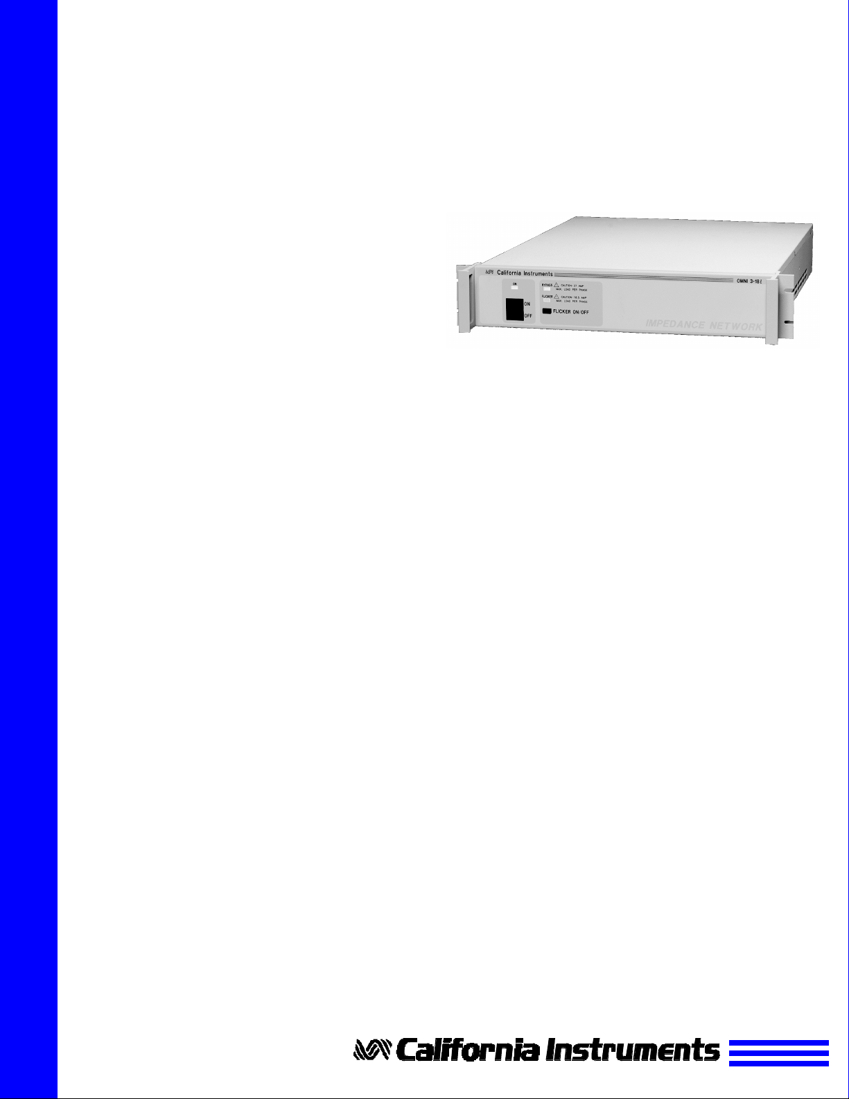
OMNI-1-18i / OMNI-3-18i
OMNI-3-37i
For IEC1000-3-3 (Flicker) Testing
Reference Impedance
Network
Flicker Tests
Existing IEC regulations require
flicker testing for a large class of
electrical and electronic equipment.
Flicker occurs when the current
drawn by an electrical device
causes a voltage drop on the line
due to the line impedance. Flicker
measurements require a controlled
environment. EN 61000-3-3 / IEC
1000-3-3 deals with flicker
measurement requirements. This
standard describes the required test
setup, which includes a precision
AC source having a specific
impedance. By measuring the
voltage drop across the standard
impedance caused by the change in
current drawn by the EUT
(Equipment Under Test), the amount
of flicker caused by the load can be
determined. The characteristics of
the standard impedance must be
precisely controlled at the test
frequency of 50 Hz.
OMNI option
The OMNI-1-18i, OMNI-3-18i and
OMNI-3-37i were specifically
designed to meet the IEC 1000-3-3
reference impedance requirements
when used in conjunction with an i
Series or iX Series AC power
source. The OMNI-1-18i and OMNI3-18i are capable of handling the
maximum 16 A per phase current
required under the IEC standard.
The OMNI-3-37i supports 32 A per
phase.
Bypass Mode
Bypass mode of operation causes
the reference impedance in the EUT
power paths to be shunted to create
virtually zero impedance. This
electrically removes the reference
impedance between the source and
the EUT. In this mode, testing for
other applications such as IEC
1000-3-2 (Harmonics) that don’t
require the reference impedance is
possible without physically having to
disconnect it.
Engage Mode
The Engage mode activates the
reference impedance path. This
mode should be used for IEC 10003-3 (Flicker) test applications. The
default mode of operation for the
OMNI is the Bypass mode so it is
important to select the correct mode
of operation when performing IEC
1000-3-3 tests.
Manual Control
When used with a power system
that lacks direct control capability,
the engage or bypass mode can be
selected from the front panel. LED’s
clearly indicate the status of the
OMNI. At power up, the OMNI
defaults to the bypass mode.
Remote Control
When used with the i Series or iX
Series of programmable AC power
sources, the engage or bypass
mode of operation are controlled
from the AC Source front panel, or
via the Power Source’s RS232 or
IEEE 488 interface. The OMNI front
panel is disabled in this case;
however, the LED’s still indicate the
status of the OMNI.
Functional Design
The OMNI-1-18i and OMNI-3-18i
are housed in a slim line 3.5” high
cabinet that matches the style of
the i Series and iX Series AC power
source. The OMNI-3-37i is
contained in a 5.25” high cabinet.
Either cabinet can be rack mounted
using the included rack mount
handles.
Page 2
Rack Mounting
For rack mount applications especially three phase systems - the
optional rack mount slides (-RMS)
are recommended. All units provide
carrying handles on the front of the
unit with integrated rack ears.
Ordering Information
Models:
OMNI-1-18i
Reference Impedance network
for 3001i/iX
phase AC source.
OMNI-3-18i
Reference Impedance network
for 15003i/iX
source.
OMNI-3-37i
Reference Impedance network
for 30003i/iX
source.
Note 1: Models 3001iX, 5001iX and
15003iX provide programmable
impedance (dynamic impedance)
which may be used in lieu of the
OMNI lumped impedance. California
Instruments offers the OMNI option for
those users insisting on the use of a
lumped reference impedance.
Note 2: Model 30003iX does not offer
programmable impedance. The
OMNI-3-37i is required to support IEC
Flicker tests.
Options
-RMS Rack mount Slides. The
use of rack mount slides or a
rack shelf is recommended when
installing the OMNI in a 19” rack.
Line Cord Options:
-PC1Continental Europe
-PC3United Kingdom
* One North American right angle Line cord
is included. Optional line cords are straight
which adds about 1 inch of depth.
Supplied with:
• North American Line Power
Cord
• Rack mount handles
• Instruction Manual
1
or 5001i/iX1 single
1
three phase AC
2
three phase AC
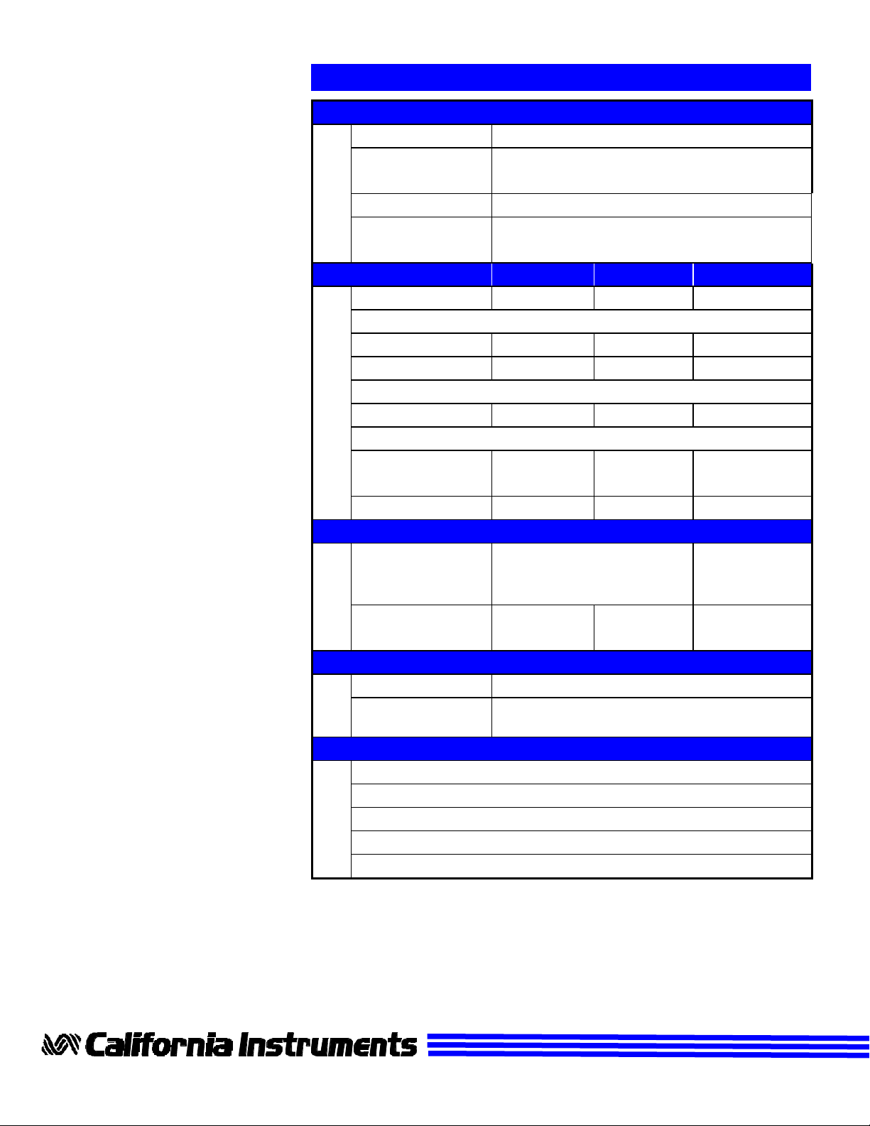
Specifications
Input
Line Voltage 115 Vac±10% / 230 Vac±10%
Line Current (typ.) 200 mA @ 115 Vac / 60 Hz
110 mA @ 230 Vac / 50 Hz
Line Frequency 47-63 Hz
Fuse Rating 0.25 A slow acting @ 115 Vac
0.125 A slow acting @ 230 Vac
Output OMNI-1-18i OMNI-3-18i OMNI-3-37i
Phases 1 3 3
Engage/Flicker Mode:
Max. Current 18.5 A 18.5 A / ø 37.0 A / ø
Useable range 2.0 - 18.5 A 2.0-18.5 A / ø 2.0 - 37.0 A / ø
Bypass Mode:
Max. Current 37.0 A 37.0 A / ø 74.0 A / ø
Impedance @ 50 Hz Engage/Flicker Mode:
Phase 0.24 + j0.15 Ω 0.24 + j0.15 Ω 0.24 + j0.15 Ω
Neutral 0.16 + j0.10 Ω 0.16 + j0.10 Ω 0.16 + j0.10 Ω
Accuracy < 5 %
Mechanical
Dimensions 3.5” x 19” x 22” 5.25” x 19” x 22”
(H x W x D) 89 x 480 x 560 mm 133x480x560
Weight 31 lbs 37 lbs 62 lbs
14 kg 17 kg 28 kg
Connectors
Input AC IEC 320
Load Input and
Output
Controls and Indicators
Power On/Off toggle switch
Flicker On/Off push button
Power Led
Bypass mode Led
Flicker mode Led
Compression terminals
Contact California Instruments:
Web page: http://www.calinst.com
< 5 % < 5 %
mm
Toll-Free: 800-4AC-POWER
800 422-7693
FAX: 858 677-0940
Email: sales@calinst.com
9689 Towne Centre Drive, San Diego CA, 92121-1964 (858) 677-9040 FAX : (858) 677-0940
Copyright 1998, California Instruments Corp. Specifications subject to change without notice Printed in the USA. OMNIDS 10/98
 Loading...