

Page 1

OF-500 OptiFiber®
PN 1779484
September 2002, Rev. 4 6/06
© 2002-2006 Fluke Corporation. All rights reserved. Printed in USA.
All product names are trademarks of their respective companies.
Certifying OTDR
Users Manual
Page 2

LIMITED WARRANTY AND LIMITATION OF LIABILITY
Each Fluke Networks product is warranted to be free from defects in material and workmanship under normal use and service. The warranty
period for the mainframe is one year and begins on the date of purchase. Parts, accessories, product repairs and services are warranted for
90 days, unless otherwise stated. Ni-Cad, Ni-MH and Li-Ion batteries, cables or other peripherals are all considered parts or accessories. The
warranty extends only to the original buyer or end user customer of a Fluke Networks authorized reseller, and does not apply to any product which, in Fluke Networks’ opinion, has been misused, abused, altered, neglected, contaminated, or damaged by accident or abnormal
conditions of operation or handling. Fluke Networks warrants that software will operate substantially in accordance with its functional
specifications for 90 days and that it has been properly recorded on non-defective media. Fluke Networks does not warrant that software
will be error free or operate without interruption.
Fluke Networks authorized resellers shall extend this warranty on new and unused products to end-user customers only but have no authority to extend a greater or different warranty on behalf of Fluke Networks. Warranty support is available only if product is purchased
through a Fluke Networks authorized sales outlet or Buyer has paid the applicable international price. Fluke Networks reserves the right to
invoice Buyer for importation costs of repair/replacement parts when product purchased in one country is submitted for repair in another
country.
Fluke Networks' warranty obligation is limited, at Fluke Networks' option, to refund of the purchase price, free of charge repair, or replacement of a defective product which is returned to a Fluke Networks authorized service center within the warranty period.
To obtain warranty service, contact your nearest Fluke Networks authorized service center to obtain return authorization information, then
send the product to that service center, with a description of the difficulty, postage and insurance prepaid (FOB Destination). Fluke Networks assumes no risk for damage in transit. Following warranty repair, the product will be returned to Buyer, transportation prepaid (FOB
Destination). If Fluke Networks determines that failure was caused by neglect, misuse, contamination, alteration, accident or abnormal
condition of operation or handling, or normal wear and tear of mechanical components, Fluke Networks will provide an estimate of repair
costs and obtain authorization before commencing the work. Following repair, the product will be returned to the Buyer transportation
prepaid and the Buyer will be billed for the repair and return transportation charges (FOB Shipping Point).
THIS WARRANTY IS BUYER'S SOLE AND EXCLUSIVE REMEDY AND IS IN LIEU OF ALL OTHER WARRANTIES, EXPRESS OR IMPLIED, INCLUDING
BUT NOT LIMITED TO ANY IMPLIED WARRANTY OF MERCHANTABILITY OR FITNESS FOR A PARTICULAR PURPOSE. FLUKE NETWORKS SHALL
NOT BE LIABLE FOR ANY SPECIAL, INDIRECT, INCIDENTAL OR CONSEQUENTIAL DAMAGES OR LOSSES, INCLUDING LOSS OF DATA, ARISING
FROM ANY CAUSE OR THEORY.
Since some countries or states do not allow limitation of the term of an implied warranty, or exclusion or limitation of incidental or consequential damages, the limitations and exclusions of this warranty may not apply to every buyer. If any provision of this Warranty is held
invalid or unenforceable by a court or other decision-maker of competent jurisdiction, such holding will not affect the validity or enforceability of any other provision.
4/04
Fluke Networks
PO Box 777
Everett, WA 98206-0777
USA
Page 3

Table of Contents
Title Page
Overview of Features.................................................................................................... 1
Accessing the Technical Reference Handbook ............................................................ 2
Registration................................................................................................................... 2
Contacting Fluke Networks .......................................................................................... 3
Unpacking ..................................................................................................................... 4
Model OF-500-01...................................................................................................... 4
Model OF-500-02...................................................................................................... 4
Model OF-500-03...................................................................................................... 5
Model OF-500-10...................................................................................................... 5
Model OF-500-13...................................................................................................... 6
Model OF-500-15...................................................................................................... 6
Model OF-500-35...................................................................................................... 7
Model OF-500-45...................................................................................................... 8
Safety Information........................................................................................................ 9
Powering the Tester...................................................................................................... 12
i
Page 4

OF-500 OptiFiber Certifying OTDR
Users Manual
Charging the Battery............................................................................................... 12
Checking the Battery Status.................................................................................... 12
Changing the Language............................................................................................... 14
Removing and Installing the Module.......................................................................... 14
Verifying Operation ..................................................................................................... 15
Basic Features ............................................................................................................... 16
Front Panel Features................................................................................................ 16
Side and Top Panel Features................................................................................... 18
The HOME Screen .................................................................................................... 20
Using the Setup Menus ........................................................................................... 22
Using the Online Help ............................................................................................. 24
Fiber ID Options....................................................................................................... 24
Checking the Tester’s Status ........................................................................................ 25
Preparing to Save Tests ................................................................................................ 26
Cleaning and Inspecting Fiber Connectors and Adapters .......................................... 27
Testing Your Reference Test Cords and Launch Fiber................................................ 28
Using the OTDR ............................................................................................................ 28
About Launch and Receive Fibers........................................................................... 28
Selecting Auto or Manual OTDR Mode.................................................................. 29
OTDR Connection Quality ....................................................................................... 30
Running the OTDR Test........................................................................................... 31
Comparing OTDR Traces.......................................................................................... 38
Cleaning the OTDR Connector..................................................................................... 39
Using the ChannelMap Function................................................................................. 40
Using the FiberInspector Option ................................................................................. 46
Using the Loss/Length Option...................................................................................... 51
About Smart Remotes ............................................................................................. 51
Changing the Connector Adapter .......................................................................... 52
ii
Page 5

Contents
Cleaning the Loss/Length Connectors..................................................................... 54
Cleaning the OUTPUT Connector ....................................................................... 54
Cleaning the INPUT Connector........................................................................... 54
About Setting the Reference................................................................................... 55
Setting the Number of Adapters and Splices.......................................................... 56
Using Mandrels for Testing Multimode Fiber......................................................... 58
Testing in Smart Remote Mode............................................................................... 60
Testing in Loopback Mode ...................................................................................... 66
Testing in Far End Source Mode.............................................................................. 72
Using the Visual Fault Locator...................................................................................... 77
Using the Power Meter Option.................................................................................... 80
Overview of Memory Functions ................................................................................... 84
Memory Capacity and Card Sizes Supported.......................................................... 84
Clearing the Internal Memory................................................................................. 85
About LinkWare and LinkWare Stats Software........................................................... 85
Maintenance ................................................................................................................. 86
Updating the Tester’s Software............................................................................... 86
Updating via the USB or Serial Port ................................................................... 87
Updating via a Memory Card Created with LinkWare ...................................... 88
Optical Connector Care............................................................................................ 89
Replacing Reference Test Cords and Launch Fibers ............................................... 89
Replacing the Battery .............................................................................................. 90
Cleaning.................................................................................................................... 90
Storage .......................................................................................................................... 90
Calibration..................................................................................................................... 91
If Something Seems Wrong.......................................................................................... 91
Getting Help............................................................................................................. 91
Signs of a Bad OTDR Connector .............................................................................. 94
(continued)
iii
Page 6

OF-500 OptiFiber Certifying OTDR
Users Manual
Options and Accessories............................................................................................... 95
Specifications................................................................................................................ 102
Environmental and Regulatory Specifications ....................................................... 102
OTDR Specifications for OFTM-561xB Multimode Modules.................................. 103
Power Meter Specifications..................................................................................... 110
Loss/Length Specifications....................................................................................... 112
Power ....................................................................................................................... 117
Traceable Calibration Period................................................................................... 117
Certifications and Compliance................................................................................ 117
Memory for Test Results.......................................................................................... 117
Serial Interfaces ....................................................................................................... 118
Keyboard Port.......................................................................................................... 119
Video Port for FiberInspector Probe....................................................................... 119
Dimensions (with module and battery installed)................................................... 119
Weight (with module and battery installed) ......................................................... 119
Display...................................................................................................................... 119
Fan............................................................................................................................ 119
FiberInspector Probe Specifications........................................................................ 120
Index
iv
Page 7

List of Figures
Figure Title Page
1. Battery Pack Features........................................................................................................... 13
2. Removing the Module ......................................................................................................... 15
3. Front Panel Features ............................................................................................................ 16
4. Side and Top Panel Features ............................................................................................... 18
5. Home Screen for OTDR with Loss/Length Option .............................................................. 20
6. The SETUP Screen................................................................................................................. 22
7. OTDR Port Connection Quality Gauge................................................................................ 30
8. Equipment for OTDR Testing .............................................................................................. 31
9. Connecting the OTDR to Installed Fiber (no receive fiber)................................................ 33
10. Connecting the OTDR to Installed Fiber (with receive fiber)............................................. 34
11. Connecting the OTDR to Spooled Cable............................................................................. 35
12. OTDR Trace Screen............................................................................................................... 36
13. Cleaning the OTDR Connector ............................................................................................ 39
14. Equipment for ChannelMap Testing................................................................................... 41
15. ChannelMap Test Connections............................................................................................ 43
16. ChannelMap Diagram Features........................................................................................... 44
17. Equipment for FiberInspector Tests .................................................................................... 47
v
Page 8

OF-500 OptiFiber Certifying OTDR
Users Manual
18. Using the FiberInspector Probe........................................................................................... 49
19. FiberInspector Image Examples .......................................................................................... 50
20. SC, ST, LC, and FC Connector Adapters .............................................................................. 52
21. Changing the Connector Adapter ...................................................................................... 53
22. Example of How to Determine the NUMBER OF ADAPTERS Setting................................ 57
23. Wrapping a Reference test cord Around a Mandrel ......................................................... 59
24. Equipment for Loss/Length Testing in Smart Remote Mode............................................. 60
25. Smart Remote Mode Reference Connections .................................................................... 63
26. Smart Remote Mode Test Connections .............................................................................. 65
27. Equipment for Loss/Length Testing in Loopback Mode.................................................... 67
28. Loopback Mode Reference Connections............................................................................ 69
29. Loopback Mode Test Connections...................................................................................... 71
30. Equipment for Loss Testing in Far End Source Mode ........................................................ 72
31. Far End Source Mode Reference Connections ................................................................... 75
32. Far End Source Mode Test Connections ............................................................................. 76
33. Equipment for Using the Visual Fault Locator................................................................... 77
34. Using the Visual Fault Locator ............................................................................................ 79
35. Equipment for Power Meter Tests...................................................................................... 81
36. Connections for Monitoring Optical Power....................................................................... 83
37. Traces Showing Good and Bad OTDR Connectors............................................................. 94
38. Event and Attenuation Deadzone Measurement Methods .............................................. 107
vi
Page 9

List of Tables
Table Title Page
1. International Electrical Symbols.......................................................................................... 9
2. Troubleshooting the Tester................................................................................................. 92
3. Options ................................................................................................................................. 95
4. Accessories............................................................................................................................ 96
5. RS-232 Interface Cable Connections.................................................................................... 118
6. 9-to-25-Pin Adapter ............................................................................................................. 119
vii
Page 10

OF-500 OptiFiber Certifying OTDR
Users Manual
Test Equipment Depot - 800.517.8431 - 99 Washington Street Melrose, MA 02176
FAX 781.665.0780 - TestEquipmentDepot.com
Page 11

OF-500 OptiFiber Certifying OTDR
Note
While this manual describes specific operating
procedures for the OptiFiber tester, the fiber
test methods described are provided only as
guidelines. Your test methods may vary.
Overview of Features
The OF-500 OptiFiber® Certifying OTDR (hereafter
referred to as the tester) is a hand-held Optical Time
Domain Reflectometer (OTDR) that locates and
characterizes reflective and loss events in multimode and
singlemode fibers. The tester is optimized for use on the
shorter fiber runs typically installed in premises (building
and campus) networks. Typical test ranges are up to 7 km
at 1300 nm for multimode fiber and up to 60 km for
singlemode fiber.
The tester offers the following features:
• Automated OTDR trace and event analysis help you
identify and locate faults on multimode (850 nm and
1300 nm; 50 µm and 62.5 µm) and singlemode
(1310 nm and 1550 nm; 9 µm) fiber.
• Displays OTDR results in summary format, as a table
of events, or as an interpretive OTDR trace.
PASS/FAIL results are based on factory-installed limits
or limits you specify.
• ChannelMap
of the connectors and segment lengths in a channel.
• Optional FiberInspector
inspect fiber endfaces and save the images.
function provides an intuitive diagram
Video Probe lets you
1
Page 12

OF-500 OptiFiber Certifying OTDR
Users Manual
• Optional modules add visual fault locator (OFTM-
57xx only), power meter, and loss/length test set
functions to the standard OTDR.
• Interchangeable connector adapters on the input
ports of the loss/length modules allow ISO-compliant
reference and test connections with a variety of
connector types.
• Saves hundreds of test results on a removable
memory card or in internal memory.
• Context-sensitive online help gives you quick access
to operating instructions and fiber troubleshooting
information.
• LinkWare
PC and create professional-quality test reports. The
LinkWare Stats option generates browsable,
graphical reports of cable test statistics.
software lets you upload test results to a
Accessing the Technical Reference Handbook
The OF-500 OptiFiber Technical Reference Handbook
provides additional information on the tester. The
handbook is available on the OptiFiber Product CD
included with your tester and on the OptiFiber product
page on the Fluke Networks website.
Registration
Registering your product with Fluke Networks gives you
access to valuable information on product updates,
troubleshooting tips, and other support services. To
register, fill out the online registration form on the Fluke
Networks website at
www.flukenetworks.com/registration.
2
Page 13

Page 14

OF-500 OptiFiber Certifying OTDR
Users Manual
Unpacking
The OF-500 OptiFiber packages come with the accessories
listed below. If something is damaged or missing, contact
the place of purchase immediately.
Model numbers followed by a "/50M" include
50/125 µm accessories instead of 62.5/125 µm accessories
Model OF-500-01
• OF-500 OptiFiber tester with battery pack
• OFTM-5610B multimode OTDR module
• 62.5/125 µm multimode launch fiber (gray zipper),
100 m, SC/SC
• Protective carrying case for tester
• Carrying strap
• Memory card
• USB cable for PC communications
• AC adapter
• Users Manual
• Product Manuals CD
• LinkWare Software CD
Model OF-500-02
• OF-500 OptiFiber tester with battery pack
• OFTM-5611B multimode OTDR module with power
meter option
• 62.5/125 µm multimode launch fiber (gray zipper),
100 m, SC/SC
• Two 62.5/125 µm multimode duplex reference test
cords, 2 m, SC/SC
• Two gray mandrels for 62.5/125 µm fiber with 3 mm
jackets
• Protective carrying case for tester
• Carrying strap
• Memory card
• USB cable for PC communications
• AC adapter
• Users Manual
• Product Manuals CD
• LinkWare Software CD
4
Page 15

Unpacking
Model OF-500-03
• OF-500 OptiFiber tester with battery pack
• OFTM-5730 singlemode OTDR module
• 9/125 µm singlemode launch fiber (yellow zipper),
130 m, SC/SC
• Protective carrying case for tester
• Carrying strap
• Memory card
• USB cable for PC communications
• AC adapter
• Users Manual
• Product Manuals CD
• LinkWare Software CD
Model OF-500-10
• OF-500 OptiFiber tester with battery pack
• OFTM-5612B multimode OTDR module with power
meter and loss/length options
• OFTM-5352 FiberInspector Video Probe (250X/400X)
with adapter tip kit
• 62.5/125 µm multimode launch fiber (gray zipper),
100 m , SC/SC
• Two 62.5/125 µm multimode duplex reference test
cords, 2 m, SC/SC
• Two gray mandrels for 62.5/125 µm fiber with 3 mm
jackets
• Protective carrying case for tester
• Carrying strap
• Soft carrying case for accessories
• Memory card
• USB memory card reader
• USB cable for PC communications
• AC adapter
• Users Manual
• Product Manuals CD
• LinkWare Software CD
5
Page 16

OF-500 OptiFiber Certifying OTDR
Users Manual
Model OF-500-13
• OF-500 OptiFiber tester with battery pack
• OFTM-5732 singlemode OTDR module with power
meter and loss/length options
• DTX Smart Remote with DTX-SFM2 singlemode fiber
module and interchangeable SC adapter
• OFTM-5352 FiberInspector Video Probe (250X/400X)
with adapter tip kit
• 9/125 µm singlemode launch fiber (yellow zipper),
130 m , SC/SC
• Two 9/125 µm singlemode duplex reference test
cords, 2 m, SC/SC
• Carrying strap
• Hard carrying case for tester
• Soft carrying case for accessories
• Memory card
• USB memory card reader
• USB cable for PC communications
• AC adapter
• Users Manual
• Product Manuals CD
• LinkWare Software CD
Model OF-500-15
• OF-500 OptiFiber tester with battery pack
• OFTM-5612B multimode OTDR module with power
meter and loss/length options
• DTX Smart Remote with DTX-MFM2 multimode fiber
module and interchangeable SC adapter
• OFTM-5352 FiberInspector Video Probe (250X/400X)
with adapter tip kit
• 62.5/125 µm multimode launch fiber (gray zipper),
100 m , SC/SC
• Two 62.5/125 µm multimode duplex reference test
cords, 2 m, SC/SC
• Two gray mandrels for 62.5/125 µm fiber with 3 mm
jackets
• OptiFiber carrying strap
• Smart Remote carrying strap
• Soft carrying case for accessories
• Hard carrying case for tester
• Memory card
• USB memory card reader
• USB cable for PC communications
• Mini-B USB cable for OptiFiber Smart Remote
• Two AC adapters
• OptiFiber Users Manual
6
Page 17

Unpacking
• OptiFiber Product Manuals CD
• Smart Remote Users Manual
• Smart Remote Product CD
• LinkWare Software CD
Model OF-500-35
• OF-500 OptiFiber tester with battery pack
• OFTM-5612B multimode OTDR module with power
meter and loss/length options
• OFTM-5732 singlemode OTDR module with power
meter and loss/length options
• OFTM-5352 FiberInspector Video Probe (250X/400X)
with adapter tip kit
• 62.5/125 µm multimode launch fiber (gray zipper),
100 m , SC/SC
• 9/125 µm singlemode launch fiber (yellow zipper),
130 m , SC/SC
• Two 62.5/125 µm multimode duplex reference test
cords, 2 m, SC/SC
• Two gray mandrels for 62.5/125 µm fiber with 3 mm
jackets
• Two 9/125 µm singlemode duplex reference test
cords, 2 m, SC/SC
• Carrying strap
• Soft carrying case for accessories
• Hard carrying case for tester
• Memory card
• USB memory card reader
• USB cable for PC communications
• AC adapter
• Users Manual
• Product Manuals CD
• LinkWare Software CD
7
Page 18

OF-500 OptiFiber Certifying OTDR
Users Manual
Model OF-500-45
• OF-500 OptiFiber tester with battery pack
• OFTM-5612B multimode OTDR module with power
meter and loss/length options
• OFTM-5732 singlemode OTDR module with power
meter and loss/length options
• DTX Smart Remote with DTX-MFM2 multimode fiber
module and interchangeable SC adapter
• DTX-SFM2 singlemode fiber module and
interchangeable SC adapter
• OFTM-5352 FiberInspector Video Probe (250X/400X)
with adapter tip kit
• 62.5/125 µm multimode launch fiber (gray zipper),
100 m , SC/SC
• 50/125 µm multimode launch fiber (aqua zipper),
100 m , SC/SC
• 9/125 µm singlemode launch fiber (yellow zipper),
130 m , SC/SC
• Two 62.5/125 µm multimode duplex reference test
cords, 2 m, SC/SC
• Two 50/125 µm multimode duplex reference test
cords, 2 m, SC/SC
• Two red mandrels for 62.5/125 µm fiber with 3 mm
jackets
• Two gray mandrels for 62.5/125 µm fiber with 3 mm
jackets
• Two 9/125 µm singlemode duplex reference test
cords, 2 m, SC/SC
• Carrying strap
• Protective carrying case for accessories
• Hard carrying case for tester
• Protective carrying case for tester
• Memory card reader
• Memory card
• USB cable for PC communications
• Two AC adapters
• Users Manual
• Product Manuals CD
• LinkWare Software CD
8
Page 19

Safety Information
*
W
Safety Information
Table 1 shows the international electrical symbols used
on the tester or in this manual.
Table 1. International Electrical Symbols
X
W
*
Warning: Risk of fire, electric shock, or personal
injury.
Warning or Caution: Risk of damage or
destruction to equipment or software. See
explanations in the manuals.
Warning: Class 1 laser (OUTPUT port). Risk of eye
damage from hazardous radiation.
Do not put products containing circuit boards
~
into the garbage. Dispose of circuit boards in
accordance with local regulations.
To avoid possible eye damage caused by
hazardous radiation and to avoid possible fire,
electric shock, or personal injury:
• Never look directly into optical connectors.
Some sources produce invisible radiation that
can permanently damage your eyes.
• Never run any tests that activate the tester’s
outputs unless a fiber is attached to the output.
• Do not open the case; no user-serviceable parts
are inside.
• Do not modify the tester.
• Do not use magnification to view the optical
outputs without proper filtering.
• Use of controls, adjustments, or procedures not
stated herein might result in hazardous
radiation exposure.
• Use only the ac adapter provided to charge the
battery or power the tester.
• Do not use the tester if it is damaged. Inspect
the tester before use.
Warning
9
Page 20

OF-500 OptiFiber Certifying OTDR
Users Manual
• If this equipment is used in a manner not
specified by the manufacturer, the protection
provided by the equipment may be impaired.
WCaution
To avoid damaging the tester or cables under
test and to avoid data loss:
• Always turn the tester off before removing or
installing a module.
• Never connect the OTDR port to an optical
source. Doing so can damage the OTDR
receiver.
• Never connect the tester to an active network,
except when using the power meter. Doing so
causes unreliable test results and can disrupt
network operations.
• If the tester shows an error because the power
reading is too high, immediately disconnect the
source from the tester. The tester is not
designed for measuring higher power levels,
such as produced by CATV, optical amplifiers,
and cellular systems.
• Avoid touching reflective surfaces (such as
metal) to the end of a fiber cable plugged into
the OTDR when the OTDR is operating. An
open fiber connector end face has about a 4%
reflection. Holding a reflective surface near the
connector end face may cause much greater
than a 4% reflection, which may damage the
photodetector in the OTDR.
• Use proper cleaning procedures to clean all
fiber connectors before every use. Neglecting
this step or using improper procedures can
cause unreliable test results and may
permanently damage the connectors.
• Use a Fluke Networks FiberInspector Video
Microscope to periodically inspect the OTDR
and loss/length option’s OUTPUT connectors for
scratches and other damage.
10
Test Equipment Depot - 800.517.8431 - 99 Washington Street Melrose, MA 02176
FAX 781.665.0780 - TestEquipmentDepot.com
Page 21

Safety Information
• Read the instructions for splice machines before
using the OTDR to monitor splicing procedures.
The OTDR can interfere with the light injection
detection techniques used by some splicers.
• To avoid unreliable test results, connect the ac
adapter or replace the battery as soon as the
low battery indication appears.
• You may use a PC to move or copy test record
(.tst) files from a memory card, but do not
rename the .tst files. Doing so may result in loss
of data.
• Never remove the memory card while the
memory card’s LED is on. Doing so can corrupt
the data on the card.
11
Page 22

OF-500 OptiFiber Certifying OTDR
Users Manual
Powering the Tester
You can power the tester with the ac adapter included or
with the removable lithium ion battery pack.
I to turn the tester on.
Press
Charging the Battery
Before you rely on battery power for the first time,
charge the battery for about 2 hours with the tester
turned off.
You can also charge the battery when it is detached from
the tester, as shown in Figure 1.
A fully-charged battery lasts about 8 hours during typical
use. The battery typically takes about 4 hours to fully
charge when the tester is turned off.
Notes
You do not need to fully discharge the battery
before recharging it.
The battery will not charge if its temperature is
outside the range of 32 °F to 113 °F (0 °C to
45 °C).
Checking the Battery Status
Many of the tester’s screens show a battery status icon
( ) near the lower-right corner.
To see more information about the battery status, press
F; then select Battery Status. Press H for detailed
information about the battery status screen.
12
Page 23
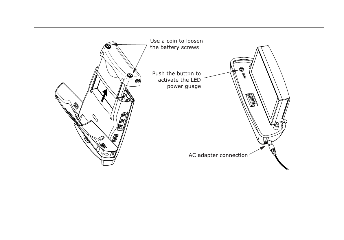
Powering the Tester
ajt20f.eps
Figure 1. Battery Pack Features
13
Page 24

OF-500 OptiFiber Certifying OTDR
Users Manual
Changing the Language
To change the tester’s language, do the following:
1 Press
2 Press
3 Press
4 Use ML to select the desired language; then press
5 Restart the tester to apply the new language.
Additional languages for the tester may be available
with software updates available on the Fluke Networks
website. Use LinkWare software to install or remove
languages. See “Updating the Tester’s Software” on
page 86 for details.
S.
N once to select the System tab.
L to select LANGUAGE; then press t.
t.
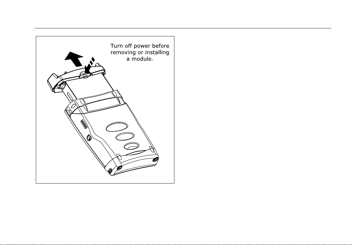
Removing and Installing the Module
The tester’s capabilities depend on which test module is
installed. Figure 2 shows how to remove the module.
WCaution
To avoid corrupting the tester's software,
always turn the tester off before removing or
installing a module.
14
Page 25
Verifying Operation
Verifying Operation
The tester performs a basic self-test when you turn it on.
If the tester reports an error or does not turn on, refer to
“If Something Seems Wrong” on page 91.
The tester shows the model number of the installed
module in the upper-right corner of the screen. If the
screen shows No Module Installed, Problem with
Module, or The module needs a software update refer to
“If Something Seems Wrong” on page 91.
Figure 2. Removing the Module
ajt56f.eps
15
Page 26
OF-500 OptiFiber Certifying OTDR
Users Manual
Basic Features
The following sections describe the tester's basic features
and introduce the tester's menu system.
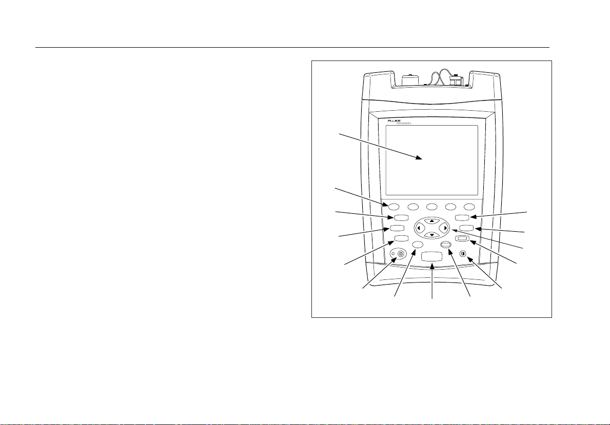
Front Panel Features
Figure 3 describes the tester’s front panel features.
16
A
N
M
L
K
F1
FUNCTIONS
SETUP
FIBER
INSPECTOR
F2
HELP
F4 F5
F3
SAVE
ENTER
TEST
J
I
Figure 3. Front Panel Features
H
OPTIFIBER
VIEW
RECORDS
EXIT
G
F
E
B
C
D
ajt12f.eps
Page 27

Basic Features
A
LCD display with backlight and adjustable brightness.
B s: Saves test results on the removable memory
card or in internal memory.
I H: Shows a help topic related to the current screen.
To see the help index, press
H again.
J I: On/off key.
C v: Shows the test records saved on the memory
card or in internal memory.
D K N L M: Navigation keys let you move the cursor
or highlighted area on the screen and increment or
decrement alphanumeric values.
E e: Exits the current screen.
F J: Lets you adjust the display brightness.
G t: Selects the highlighted item on the screen.
H T: Starts the currently selected fiber test. The test
that will run is shown in the upper-left corner of the
display. To change the test, press
from the HOME screen or select a test from the
FUNCTIONS menu.
A Change Test
Figure 3. Front Panel Features (cont.)
K f: Activates the optional FiberInspector video
probe, which lets you inspect fiber endfaces and save
the images with test results.
L F: Shows a list of additional test, configuration,
and status functions.
M S: Shows the menus you use to configure the
tester.
N A B C D E: The five softkeys provide
functions related to the current screen. The current
functions are shown on the screen above the keys.
17
Page 28

OF-500 OptiFiber Certifying OTDR
Users Manual
Side and Top Panel Features
Figure 4 describes the tester’s connectors and other
features on the side and top panels.
Figure 4. Side and Top Panel Features
ajt14f.eps
18
Page 29

Basic Features
A
Connector for the ac adapter. The LED turns on when the
adapter is connected to ac power.
B USB port for uploading test reports to a PC and
downloading software updates from a PC to the tester.
See the LinkWare documentation for details on using the
USB port.
C Six-pin mini DIN connector for an optional external PS2
keyboard.
D Eight-pin mini DIN connector for the optional
FiberInspector video probe.
E Fan vents.
F RS-232C serial port for uploading test reports to a PC and
downloading software updates from a PC to the tester.
See the LinkWare documentation for details on using the
serial port.
G Slot for the removable memory card. The LED lights when
the tester is writing to or reading from the memory card.
H Multimode (MM) or singlemode (SM) label for the module.
Figure 4. Side and Top Panel Features (cont.)
I OFTM-57xx: Connector for the visual fault locator.
J OTDR connector adapter (SC is standard). The LED
lights when the laser is active.
K OFTM-5612B/5732: Loss/length output port (SC).
Transmits optical signals for loss/length tests.
L OFTM-5731/5732/5611B/5612B: Loss/length input
port with interchangeable connector adapter (SC is
standard). Receives optical signals for power
measurements and loss/length tests.
*
W
Never look directly into optical connectors.
Some sources produce invisible radiation that
can permanently damage your eyes.
Warning
M Laser safety label (shown below).
CAUTION
ajt72f.eps
19
Page 30
OF-500 OptiFiber Certifying OTDR
Users Manual
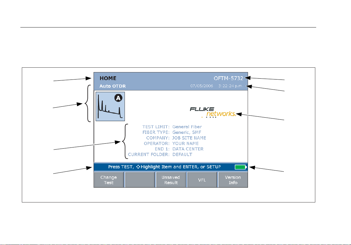
The HOME Screen
The HOME screen shows important test and job settings
you might need to change to configure the tester for your
needs. Figure 5 describes a typical home screen.
L
K
J
I
H
Figure 5. Home Screen for OTDR with Loss/Length Option
G
F
E
A
B
C
D
ajt13f.eps
20
Test Equipment Depot - 800.517.8431 - 99 Washington Street Melrose, MA 02176
FAX 781.665.0780 - TestEquipmentDepot.com
Page 31

Basic Features
A
Model number of the installed module.
B The current date and time.
I Action prompts. For most screens, this area prompts
you on what keys to press.
J Important test and job settings. To change these
C Owner’s logo. See the OptiFiber Technical Reference
Handbook (on the Product Manuals CD) or the LinkWare
online help for information on changing the logo.
D Battery status icon. For more information about the
battery, press F; then select Battery Status.
E Press E to see the hardware and software versions and
calibration dates for the tester and the installed module.
F Press D VFL to activate the visual fault locator.
G If the last test run was not saved, you can press
settings, use KLMNto highlight a setting; then
t. Selecting TEST LIMIT or FIBER TYPE lets
press
you change the item. Selecting the limit’s or type’s
name lets you see that item’s settings. You may also
access the tester’s settings by pressing
S.
K The test mode, which determines what type of test
will run when you press T. The available modes
depend on which module is installed. To change the
test mode, press A Change Test.
L The name of the current screen.
C Unsaved Result to see the test’s results.
H Press A Change Test to switch test modes. See K.
Figure 5. Home Screen for OTDR with Loss/Length Option (cont.)
21
Page 32

OF-500 OptiFiber Certifying OTDR
Users Manual
Using the Setup Menus
To access the tester’s settings, press S. Figure 6
introduces the SETUP menus.
C
Figure 6. The SETUP Screen
A
B
ajt17f.eps
22
Page 33

Basic Features
A The settings available on the current tab.
Note
To see details about a setting, highlight the
setting; then press H.
B Use D Tab and E Tab to move among tabs on
the SETUP screen.
C Tabs for the setup menus:
• Job settings apply to the fiber installation you are
testing and are stored with saved test results. Use
these settings to identify the job site, set up cable ID
lists, and identify which end of the cabling you are
testing.
• System settings let you localize the tester and set
other user preferences, such as the power down
timeout and camera type.
Figure 6. The Setup Screen (cont.)
• The Cable tab lets you select the type of fiber cable you
will test and define some cable characteristics for
loss/length tests. You can also change the index of
refraction if you do not want to use the default values.
Note
Select a fiber type before selecting a test limit. The
fiber type determines which test limits are available.
• The OTDR tab lets you select a test limit and wavelength
for OTDR tests and enable launch fiber compensation. You
can also change settings for Manual OTDR mode.
• The Loss/Length tab appears if the installed module
includes the loss/length or power meter option (you can
run loss tests in Far End Source mode with the power
meter option). Use this tab to configure the loss/length
test. See “Using the Loss/Length Option” on page 51 for
details.
Different or additional tabs may be available depending on
the installed module.
23
Page 34

OF-500 OptiFiber Certifying OTDR
Users Manual
Using the Online Help
When you press H, the tester shows a help topic that
relates to the current screen. Blue, underlined words are
links to other topics.
Note
The help files are stored in the mainframe
(rather than the module) and may describe
features not present in the installed module
To go to a linked topic (blue, underlined words), use the
left or right arrow keys to highlight the words; then press
t.
To see an index of all help topics, press
are in the help system.
H any time you
Fiber ID Options
You can create or select fiber IDs as follows:
• You can create an ID after you press s. You can
also highlight a used or unused ID in a list; then press
t to edit it into a new ID. The next time you press
s, the tester increments the last character of the
ID you created (the auto increment feature).
• You can create a list of sequential fiber IDs by
configuring a template on the Job tab in Setup.
Select the IDs from the AUTO SEQ IDs list after you
press s.
• You can create ID lists in LinkWare software; then
download them to the tester. Select the IDs from the
DOWNLOAD IDs list after you press s.
• After you press
assigned to a record stored in the current folder. This
lets you overwrite existing results or add new results
to an existing record. Select the ID from the IDs IN
CURRENT FOLDER list after you press
s, you can use an ID already
s.
24
Page 35

Checking the Tester’s Status
Checking the Tester’s Status
The following steps help you verify that the tester is ready
for use.
Checking the Tester’s Status
Check the battery status
Look at the battery icon in the lower-left corner of the
screen or press
A fully-charged battery lasts about 8 hours during
typical use.
Check the space available on the memory card
Insert the memory card you will use, press
select Memory Status.
To see the status of the internal memory, press
A from the MEMORY STATUS screen.
F; then select Battery Status.
F; then
To view or delete stored records, press
To format the memory card press F; then select
Format Memory Card.
Verify that the installed module can run the tests you
need
The module’s model number is shown in the upperright corner of the screen.
To review module capabilities, press H twice; then
select “modules” in the OptiFiber online help index.
v.
25
Page 36

OF-500 OptiFiber Certifying OTDR
Users Manual
Preparing to Save Tests
The following steps summarize how to configure settings
that apply to saved test results.
Preparing to Save Tests
Set up a job folder
1 Insert a memory card into the tester.
2 Press
3 Select an existing folder on the memory card, or
Enable or disable the SAVE WARNING
Press
tab to enable or disable the warning about an unsaved
test.
Enter COMPANY and OPERATOR names on the Job
tab
COMPANY is the customer name, job site, job work
order, or other job identifier.
S; then select CURRENT FOLDER on the
Job tab.
press
A New Folder to create a new folder.
S; then select SAVE WARNING on the System
Create a list of sequential fiber IDs (See “Fiber ID
Options” on page 24 for other ID options.)
1 Select AUTO SEQ TEMPLATE on the Job tab.
2 Press
3 Press
4 Press
Identify the ends of the cabling
1 Enter names for END 1 and END 2 on the Job tab.
2 Set THIS END to the end you will test from first.
A Change Template to select an ID
template.
B Edit Start or C Edit Stop to create the
start and stop IDs; then press E Sample List to
see what the list will look like.
s when you are finished.
For example, one end could be TELECOM ROOM
and the other could be WORK AREA.
OPERATOR is the name of the OptiFiber user.
26
Page 37

Cleaning and Inspecting Fiber Connectors and Adapters
Cleaning and Inspecting Fiber Connectors and Adapters
Always clean and inspect fiber connectors before making
connections. Use 99 %-pure isopropyl alcohol and
optical-grade wipes or swabs to clean fiber connectors as
follows:
WCaution
See pages 39 and 52 for instructions on cleaning
the tester's OTDR and loss/length connectors.
• Connector ends: Wipe the end of the ferrule with a
swab or wipe lightly moistened with alcohol. Dry
with a dry swab or wipe.
• Bulkhead adapters:
1 Touch the tip of a lint-free foam swab to an
alcohol-soaked cleaning pad.
2 Push the swab into the adapter; twist it around
3 to 5 times against the endface, then remove
and dispose of the swab.
3 Dry the endface with a dry, lint-free swab by
twisting it around in the adapter 3 to 5 times.
• Inspect connectors with a fiber microscope, such as
the Fluke Networks FiberInspector Video Probe
before making connections. See “Using the
FiberInspector Option” on page 46 for details.
• Periodically clean fiber adapters with a swab and
alcohol. Dry adapters with a dry swab before use.
• Always cover unused connectors with dust caps or
plugs. Clean dust plugs periodically with a swab or
wipe and alcohol.
27
Page 38

OF-500 OptiFiber Certifying OTDR
Users Manual
Testing Your Reference Test Cords and Launch Fiber
You should test your reference test cords and launch
fiber before each job. Use another set of known-good
cords to set a reference and run an Autotest on each cord
and launch fiber. Use Smart Remote mode to test two
cords at a time, or Loopback mode to test one cord.
You should also use a fiber microscope, such as the
FiberInspector video probe, to inspect the reference test
cord and launch fiber connectors for damage at least
once a day.
Using the OTDR
The OTDR helps you identify and locate faults on fiber
cabling. It also measures length, event loss, and overall
loss of the cabling and provides PASS/FAIL results based
on a selected test limit.
About Launch and Receive Fibers
Launch and receive fibers let the tester measure the loss
and reflectance of the first and last connectors in the
cabling, and include those connectors in ORL (optical
return loss) measurements. Without launch and receive
fibers, no backscatter is available before the first
connector and after the last, so the tester cannot
measure the connectors’ characteristics.
If the first or last connection in the cabling is bad, and
you do not use launch and receive fibers, the OTDR test
may pass because it does include measurements from the
bad connection.
28
Page 39

Using the OTDR
OVERALL LOSS and FIBER LENGTH include the loss and
length of the launch and receive fibers, unless you use
the launch/receive fiber compensation function. See the
online help or the Technical Reference Handbook for
details on launch fiber compensation.
Fluke Networks recommends that you use launch and
receive fibers. You should also use launch/receive fiber
compensation to remove the effects of these fibers from
the OTDR measurements.
Note
Avoid using hybrid patch cords to connect to the cabling
under test. Connect the launch and receive fibers directly
to the cabling under test, using a launch fiber with the
appropriate connectors. This provides the best view of
the connectors at the ends of the cabling. Hybrid launch
fibers with various connector styles are available from
Fluke Networks.
Selecting Auto or Manual OTDR Mode
Note
You should use Auto OTDR mode when
certifying cabling with the OTDR.
From the HOME screen, press
Auto OTDR or Manual OTDR from the popup menu.
In Auto OTDR mode, the tester automatically selects
settings based on the length and overall loss of the
cabling. This mode is the easiest to use, provides the most
comprehensive view of the events on the cabling, and is
the best choice for most applications.
Manual OTDR mode lets you change settings to optimize
the OTDR for displaying specific events. See the online
help or the Technical Reference Handbook for details.
A Change Test. Select
29
Page 40

OF-500 OptiFiber Certifying OTDR
Users Manual
OTDR Connection Quality
When you run an OTDR test, the tester determines the
quality of OTDR port connection (Figure 7).
If the gauge is in the Poor range, you should clean the
OTDR port and the fiber connector. Use a video
microscope, such as the FiberInspector video probe, to
inspect the port and fiber connector for scratches and
other damage. If a connector on the tester is damaged,
contact Fluke Networks for service information.
A poor OTDR connection increases the connector’s
deadzone, as shown in Figure 37 on page 94. The
deadzone can hide faults near the OTDR connector.
A poor connection also decreases the light available for
testing the fiber. The weakened test signal causes a
noisier trace, poor event detection, and decreased
dynamic range.
The port connection quality rating is saved with OTDR
result details.
Figure 7. OTDR Port Connection Quality Gauge
ajt67f.eps
30
Test Equipment Depot - 800.517.8431 - 99 Washington Street Melrose, MA 02176
FAX 781.665.0780 - TestEquipmentDepot.com
Page 41

Using the OTDR
Running the OTDR Test
Figure 8 shows the equipment needed for using the
OTDR.
A Tester with OFTM-56xxB or OFTM-57xx module
B Memory card (optional)
C Spare battery pack (optional)
D AC adapter with line cord (optional)
Figure 8. Equipment for OTDR Testing
ajt42f.eps
E Launch fiber and receive fibers. Match the fiber to be
tested. Match cable connectors at one end when
possible.
F Fiber cleaning supplies
31
Page 42

OF-500 OptiFiber Certifying OTDR
Users Manual
Using the OTDR
1 Select Auto OTDR mode: On the HOME screen, press
A Change Test; then select Auto OTDR.
2 Compensate for the launch/receive fibers, if desired:
F; then select Set Launch Fiber Compensation.
Press
Press H for details on the compensation screens.
3 Choose settings for the fiber to be tested. Set the
following on the Cable tab:
• FIBER TYPE: Select the fiber type to be tested.
• MANUAL CABLE SETTINGS (index of refraction
and backscatter coefficient): Disable to use the
values defined in the selected fiber type, which are
suitable for most applications.
4 Configure the OTDR test. Press
following on the OTDR tab:
• TEST LIMIT: Select an appropriate limit.
• WAVELENGTH: Select one or both wavelengths.
• LAUNCH COMPENSATION: Enable if you want to
use the launch fiber compensation settings.
• OTDR PLOT GRID: Enable to see a measurement
grid on the OTDR plot.
S; then select the
5 Clean the connectors on the launch fiber and the fiber
to be tested.
6 Clean all connectors that will be used.
7 Connect the tester's OTDR port to the cabling, as shown
in Figure 9, 10, or 11.
8 Press
9 To save the results, press
For bi-directional testing, do the following:
1 Set THIS END to END 1 on the Job tab in Setup.
2 Test all the cabling from END 1.
3 Change THIS END to END 2; then test all the cabling
T to start the OTDR test. Figure 12 describes
the OTDR trace screen.
s, select or create a fiber
ID; then press
from the other end. Save the results with the same fiber
IDs as results from the first test direction. The ID will be
in the IDs IN CURRENT FOLDER list.
s again.
32
Page 43

Using the OTDR
Figure 9. Connecting the OTDR to Installed Fiber (no receive fiber)
ajt32f.eps
33
Page 44

OF-500 OptiFiber Certifying OTDR
Users Manual
34
Figure 10. Connecting the OTDR to Installed Fiber (with receive fiber)
ajt01f.eps
Page 45

Using the OTDR
Figure 11. Connecting the OTDR to Spooled Cable
ajt33f.eps
35
Page 46

OF-500 OptiFiber Certifying OTDR
Users Manual
A
B
36
N
M
L
K
HIJ
Figure 12. OTDR Trace Screen
G
F
C
D
E
ajt16f.eps
Page 47

Using the OTDR
A
Wavelength for the trace and the End setting on the
Job tab in SETUP. If the test ran at two wavelengths,
A to switch wavelengths. You can set the
press
wavelengths on the OTDR tab in Setup.
B Magnification factors for the trace. See the online help
for details on zooming.
C The distance (m or ft) and the power loss (dB) between
the cursor and the measurement marker (M).
D OTDR plot grid. You can enable or disable the grid on
the OTDR tab in SETUP.
E PASS/FAIL status appears if the cursor is on an event.
The status may refer to the event or the fiber segment
before the event. If the event looks ok, press C View
Details from the EVENT TABLE screen or the
SUMMARY screen to see results for the segment.
F Press E to change the arrow keys’ function from
moving the cursor to zooming to moving the trace if
trace overlay is active (page 38). The navigational cue
above the softkey labels describes the arrow keys’
current function.
Figure 12. OTDR Trace Screen (cont.)
G Key for setting and clearing the measurement cursor.
H Moves the cursor to the next event on the trace. If you
use K to move the cursor, C changes to Previous
Event and moves the cursor to the previous event.
I Displays the event table.
J For dual-wavelength tests, press A to switch
wavelengths.
K Event information appears if the cursor is on an event.
Otherwise, the distance to the cursor is shown.
L Scale for the distance along the cabling under test.
Tip: The distance scale represents the distance along the
fiber, which may be different from the distance along
the cable jacket. To adjust the length measurements
to represent cable jacket length, change the index of
refraction until the measured length matches the
jacket length.
M Measurement marker and cursor.
N Decibel scale for the OTDR backscatter.
37
Page 48

OF-500 OptiFiber Certifying OTDR
Users Manual
Comparing OTDR Traces
The trace overlay function lets you see two OTDR traces
at the same time. This lets you do the following:
• Compare a link’s current trace with a past trace to
see if the link has changed.
• Compare traces from links in the same run to check
for differences.
To compare two traces, do the following:
1 Run an OTDR test; then press
or
View an OTDR trace from a saved record.
This trace is the Comparison Trace.
2 Press
3 Select New Reference Trace.
4 On the VIEW RECORDS screen, select a record. Only
5 Press
F. This brings up the OTDR FUNCTIONS
menu.
records with OTDR traces are shown.
The test’s trace becomes the Reference Trace on the
OTDR FUNCTIONS menu.
e.
A View Trace.
The reference trace stays on the plot until you turn off
the trace overlay function.
38
Page 49

Cleaning the OTDR Connector
Cleaning the OTDR Connector
Note
Typically, the OTDR connector requires cleaning
only if it has been touched.
Use a dry, optical-grade wipe to clean the OTDR
connector. Figure 13 shows how to remove the OTDR
adapter to access the connector ferrule.
The OTDR port connection quality screen helps you
determine when the OTDR connector needs cleaning. See
page 30.
If the connector is very dirty, wipe the end of the ferrule
with an optical-grade wipe lightly moistened with 99 %pure isopropyl alcohol. Dry with a dry wipe.
Figure 13. Cleaning the OTDR Connector
ajt71f.eps
39
Page 50

OF-500 OptiFiber Certifying OTDR
Users Manual
Using the ChannelMap Function
The ChannelMap function creates a map of the cabling
under test. The map shows the fiber links and
connections in the cabling. This function is optimized for
resolving connections as close as 1 m apart on multimode
fiber and 2 m apart on singlemode fiber.
Reflective events that do not appear to be connectors are
not shown on the map. Loss events are also not shown.
Note
Since the ChannelMap function identifies only
reflections, it is not appropriate for finding fusion splices
or angled physical contact (APC) connectors.
Figure 14 shows the equipment needed for ChannelMap
tests.
40
Test Equipment Depot - 800.517.8431 - 99 Washington Street Melrose, MA 02176
FAX 781.665.0780 - TestEquipmentDepot.com
Page 51

Using the ChannelMap Function
ajt48f.eps
A Tester with OTDR module
B Memory card (optional)
C Spare battery pack (optional)
E Launch fiber or patch cord. Match fiber to be tested.
Match cable connectors at one end. SC at the other
end.
F Fiber cleaning supplies
D AC adapter with line cord (optional)
Figure 14. Equipment for ChannelMap Testing
41
Page 52

OF-500 OptiFiber Certifying OTDR
Users Manual
Using the ChannelMap Function
1 Select ChannelMap mode: On the HOME screen, press
A Change Test; then select ChannelMap.
2 Select a fiber type on the Cable tab in Setup. You do
not need to select a test limit for ChannelMap tests.
3 Clean the connectors on the launch fiber or patch cord
and the channel to be tested.
4 Connect the launch fiber to the OTDR port and the
channel to be mapped. Refer to Figure 15.
5 Press
6 To save the results, press
T. Figure 16 describes the features of the
ChannelMap diagram.
s, select or create a fiber
ID; then press s again.
42
Page 53

Using the ChannelMap Function
Figure 15. ChannelMap Test Connections
ajt55f.eps
43
Page 54

OF-500 OptiFiber Certifying OTDR
Users Manual
A
44
F
E
Figure 16. ChannelMap Diagram Features
B
C
D
ajt25f.eps
Page 55

Using the ChannelMap Function
A
The length of the channel, including the launch fiber.
Note
The FIBER LENGTH shown is the actual length of
the channel rounded to the nearest meter or foot
(not the sum of the displayed segment lengths).
B The far end of the channel. The name is set by the
END 1 or END 2 setting on the Job tab in Setup.
C The length of a segment or patch cord rounded to the
nearest meter or foot.
D Press D to add a comment to the ChannelMap
results.
E A reflective event, usually a connector. Could also be a
mechanical splice or a reflective fault such as a sharp
bend or a crack in the fiber.
F The near end of the channel. The name is set by the
END 1 or END 2 setting on the Job tab in Setup.
Figure 16. ChannelMap Diagram Features (cont.)
45
Page 56

OF-500 OptiFiber Certifying OTDR
Users Manual
Using the FiberInspector Option
The OFTM-5352 FiberInspector Video Probe connects to
an OptiFiber fiber tester to let you inspect the ends of
fiber optic connectors. The probe's 250X and 400X
magnifications reveal dirt, scratches, and other defects
that can cause poor performance or failures in fiber optic
networks.
The 250X magnification shows dirt and other defects on
the fiber endface and surrounding ferrule. The 400X
magnification allows a more detailed inspection of the
cladding and core.
Figure 17 shows the equipment needed for using the
FiberInspector probe.
46
Page 57

Using the FiberInspector Option
ajt43f.eps
A OptiFiber tester
B Memory card (optional)
C Spare battery pack (optional)
E FiberInspector probe with adapter cable and
appropriate adapter tip
F Fiber cleaning supplies
D AC adapter with line cord (optional)
Figure 17. Equipment for FiberInspector Tests
47
Page 58

OF-500 OptiFiber Certifying OTDR
Users Manual
Using the FiberInspector Probe
1 On the System tab in Setup, set CAMERA TYPE to match
the magnification you will use. This selects the correct
size for the core size scale.
2 Use the adapter cable provided to connect the probe to
the video input jack on the side of the tester.
3 Screw an adapter tip that matches the connector type
being inspected onto the fiber probe.
4 Clean the connector to be inspected.
5 Press
f. If the message “Camera Image
Unavailable” appears check the connections between
the probe and the tester.
6 Place the probe on the fiber connector. Turn the larger
ring on the probe to focus the image. Turn the smaller
ring to change magnification. Refer to Figure 18.
The tester’s softkeys provide additional functions. Press
A More to see other softkey functions.
7 To save the image, press
ID; then press s again.
Figure 19 shows some typical FiberInspector images.
s, select or create a fiber
48
Page 59

Using the FiberInspector Option
ajt57f.eps
Figure 18. Using the FiberInspector Probe
49
Page 60

OF-500 OptiFiber Certifying OTDR
Users Manual
50
far end
Wiped with fingertip
Figure 19. FiberInspector Image Examples (250X on multimode fiber)
Test Equipment Depot - 800.517.8431 - 99 Washington Street Melrose, MA 02176
Alcohol drying
Dirty patch panel connector
(left uncovered)
FAX 781.665.0780 - TestEquipmentDepot.com
Dirt on coreClean, with light at
Scratched, needs polishing
ajt23f.eps
Page 61

Using the Loss/Length Option
Using the Loss/Length Option
The loss/length measurement option provides the
following features, in addition to the OTDR module
features described earlier:
• Measures optical power loss, length, and propagation
delay on dual-fiber cabling. Provides PASS/FAIL results
based on limits you enter or on factory-installed
limits.
• FindFiber
optical connections.
The loss/length option is available with OFTM-56x2B and
OFTM-5732 modules.
feature helps you identify and verify
About Smart Remotes
You can use the following as the remote for loss/length
testing and FindFiber tests in Smart Remote mode:
• A second OptiFiber tester with the loss/length option
• A Fluke Networks DTX Series CableAnalyzer™ smart
remote with a multimode or singlemode fiber
module. The DTX remote can also be used as a
manually-controlled source for testing in Far End
Source mode. You can buy a DTX smart remote
separately for this purpose. See the Fluke Networks
website or contact Fluke Networks for details.
Note
The OptiFiber tester must have software version
1.8.8 or later to work with a DTX-xFM2 smart
remote. OptiFiber software updates are available
on the Fluke Networks website.
51
Page 62

OF-500 OptiFiber Certifying OTDR
Users Manual
Changing the Connector Adapter
You can change the module's input connector adapter
(Figure 20) to connect to SC, ST, LC, and FC fiber
connectors. Additional adapter styles may be available.
Check the Fluke Networks web site for updates.
WCaution
• Cover all connectors with dust caps when not in
use.
• Store extra connector adapters in the canisters
provided.
• Do not touch the photodiode lens (see Figure
21).
• Do not overtighten the adapter or use tools to
tighten the adapter.
To install a connector adapter, refer to Figure 21and do
the following:
1 Locate the slot in the module connector and the key
on the adapter ring.
2 Holding the adapter so it does not turn in the nut,
align the adapter's key with the module connector's
slot and slide the adapter onto the connector.
3 Screw the nut onto the module connector.
amd37f.eps
Figure 20. SC, ST, LC, and FC Connector Adapters
52
Page 63

Using the Loss/Length Option
Figure 21. Changing the Connector Adapter
ajt61f.eps
53
Page 64

OF-500 OptiFiber Certifying OTDR
Users Manual
Cleaning the Loss/Length Connectors
Always clean and inspect fiber connectors before making
connections. Use 99 %-pure isopropyl alcohol and opticalgrade wipes or swabs to clean the connectors as follows:
Cleaning the OUTPUT Connector
1 Touch the tip of a 2.5 mm lint-free foam swab in
alcohol; then touch the swab to an alcohol-soaked
cleaning pad.
2 Push the swab into the adapter; twist it around 3 to 5
times against the endface, then remove and dispose
of the swab.
3 Dry the endface with a dry swab by twisting it around
in the adapter 3 to 5 times.
4 Inspect the connector regularly with a fiber
microscope, such as the Fluke Networks
FiberInspector Video Microscope.
Cleaning the INPUT Connector
Note
Typically, the input connector requires cleaning
only if it has been touched.
1 Remove the connector adapter to expose the
photodiode lens (see Figure 21).
2 Use the method described under "Cleaning the
Output Connector" above to dampen a swab with
alcohol.
3 Twist the damp swab around against the lens 3 to 5
times; then twist a dry swab around against the lens 3
to 5 times.
54
Page 65

Using the Loss/Length Option
About Setting the Reference
Setting a reference lets the tester automatically subtract
out the losses due to reference test cords and the main
and remote tester.
Note
Always let your test equipment warm up for 5
minutes before setting a reference.
For the most accurate test results, you should set the
reference at these times:
• At the beginning of each day using the remote end
setup (Figures 25 through 32) you will use that day.
The tester reminds you to set the reference if the
reference is more than 12 hours old.
• Anytime you reconnect a reference test cord to the
tester or other source.
• Anytime the tester warns you that the reference is
out of date.
The tester requires you to set the reference at these
times:
• Anytime you change the loss/length module in the
main or remote tester.
• Anytime you start using a different remote tester.
• Thirty days after the reference was previously set.
The tester warns you if the reference value is outside of
an acceptable range.
To see the reference information for the current remote
end setup, select Set Loss/Length Reference from the
Functions menu; then press
See the sections "Testing in Smart Remote Mode",
"Testing in Loopback Mode", and "Testing in Far End
Source Mode" for details on setting the reference for
each mode.
A View Settings.
55
Page 66

OF-500 OptiFiber Certifying OTDR
Users Manual
Setting the Number of Adapters and Splices
The NUMBER OF ADAPTERS and NUMBER OF SPLICES
settings are on the Loss/Length tab in Setup. These
settings do not apply to all test limits.
Test limits that include maximum values for the loss per
km, loss per connector, and loss per splice use a
calculated limit for loss. Only limits with all three values
use a calculated loss limit. The OVERALL LOSS value
should be N/A in these limits. If a loss value is entered, it
is ignored.
To see the limit’s values, select TEST LIMIT on the
Loss/Length tab; then press
If the selected limit uses a calculated loss limit, enter the
number of adapters and splices that will be added to the
fiber path after the reference is set.
Figure 22 shows an example of how to determine the
NUMBER OF ADAPTERS setting.
A View Limit.
56
Page 67

Using the Loss/Length Option
Figure 22. Example of How to Determine the NUMBER OF ADAPTERS Setting
ajt22f.eps
57
Page 68

OF-500 OptiFiber Certifying OTDR
Users Manual
Using Mandrels for Testing Multimode Fiber
You should use mandrels when testing multimode fiber.
Mandrels can improve measurement repeatability and
consistency. They also allow the use of LED light sources
to certify 50 µm and 62.5 µm fiber links for current and
planned high bit-rate applications, such as Gigabit
Ethernet and 10 Gigabit Ethernet.
The gray mandrels included with some OptiFiber models
are compliant with TIA/EIA-568-B for 62.5 µm fiber with a
3 mm jacket.
Mandrels for 50 µm fiber are available from Fluke
Networks. Refer to the appropriate standard for mandrel
requirements if you follow other standards. The OF-500
Technical Reference Handbook provides a partial list of
mandrel requirements for TIA and ISO standards.
Figure 23 shows how to wrap the fiber around a
mandrel. Place mandrels on the tester’s output fibers, as
shown in Figures 25 through 32.
In the reference and test connection diagrams shown on
the tester, mandrels are indicated by a loop in the fiber.
58
Page 69

Using the Loss/Length Option
ajt02f.eps
Figure 23. Wrapping a Reference test cord Around a Mandrel
59
Page 70

OF-500 OptiFiber Certifying OTDR
Users Manual
Testing in Smart Remote Mode
Use Smart Remote mode to test and certify dual-fiber
cabling. In this mode, the tester measures loss, length,
and propagation delay on two fibers at two wavelengths
in one or both directions.
A Tester with OFTM-5612B or OFTM-5732 module and
smart remote (DTX remote shown). Match connector
adapters to the connectors in the link.
B Memory card (optional)
C Spare battery pack (optional)
D Two ac adapters with line cords (optional)
Figure 24 shows the equipment needed for testing in
Smart Remote mode.
ajt44f.eps
E Two duplex reference test cords. Match the fiber to be
tested. Connectors for the tester and remote outputs
must be SC. For the others match the connectors in the
link.
F Two mandrels. Recommended when testing multimode
fiber. See page 58.
G Fiber cleaning supplies
60
Figure 24. Equipment for Loss/Length Testing in Smart Remote Mode
Test Equipment Depot - 800.517.8431 - 99 Washington Street Melrose, MA 02176
FAX 781.665.0780 - TestEquipmentDepot.com
Page 71

Using the Loss/Length Option
Loss/Length Testing in Smart Remote Mode
1 Turn on all test equipment and let it warm up for 5
minutes.
2 On the main tester: On the HOME screen, press
Change Test; then select Loss/Length.
3 On the main tester: press
on the Cable tab:
• FIBER TYPE: Select the fiber type to be tested.
• MANUAL CABLE SETTINGS (index of refraction
and backscatter coefficient): Disable to use the
values defined in the selected fiber type, which are
suitable for most applications.
4 On the main tester: set the following on the
Loss/Length tab in Setup:
• TEST LIMIT: Select an appropriate limit.
• REMOTE END SETUP: Set to Smart Remote.
• THIS UNIT: Set to Main.
• BI-DIRECTIONAL: Enable this if you want to save bi-
directional results.
S; then set the following
A
• TEST METHOD: Refers to the number of adapters
that are represented in the loss results. Select
Method B (multimode) or A.1 (singlemode) if you
use the reference and test connections shown in
this manual. See the online help or the Technical
Reference Handbook for details.
• CONNECTOR TYPE: Select connector type used in
the cabling to be tested. Select General if the exact
type is not listed.
• NUMBER OF ADAPTERS and NUMBER OF SPLICES:
Enter the number of adapters and splices that will
be added to each direction of the fiber path after
the reference is set. See “Setting the Number of
Adapters and Splices” on page 56 for details.
5 For an OptiFiber Smart Remote: set the following on
the Loss/Length tab in Setup
• REMOTE END SETUP: Set to Smart Remote.
• THIS UNIT: Set to Remote.
-continued-
61
Page 72

OF-500 OptiFiber Certifying OTDR
Users Manual
Loss/Length Testing in Smart Remote Mode (cont.)
6 Clean the tester's and source's OUTPUT connectors and
the reference test cord connectors.
7 On the main tester: press
Loss/Length Reference.
8 Connect the reference test cords as shown on the screen
and in Figure 25; then press
F; then select Set
t.
9 Optional: From the TEST SETUP screen, you can enter
reference test cord lengths to meet TSB-140 reporting
requirements:
Use
L to highlight a reference test cord number, press
t; then enter a length. Press N when you are done.
10 Press
C OK to leave the TEST SETUP screen.
WCaution
If you disconnect the reference test cords from the
tester's or remote's output, you must set the
reference again to ensure valid measurements.
-continued-
62
Page 73

Using the Loss/Length Option
Figure 25. Smart Remote Mode Reference Connections
ajt05f.eps
63
Page 74

OF-500 OptiFiber Certifying OTDR
Users Manual
Loss/Length Testing in Smart Remote Mode (cont.)
11 Clean the connectors on the cabling to be tested; then
connect the reference test cords and the short patch
cords to the cabling, as shown in Figure 26.
12 Press
T to start the loss/length test.
If Open or Unknown appears as the status, try the
following:
• Verify that all connections are good.
• For an OptiFiber smart remote verify that the
remote tester is set to Remote on its Loss/Length
tab in Setup.
• Verify that the remote tester is still active. For an
OptiFiber smart remote you may need to press
Start on the remote tester to reactivate the tester.
• Try different connections to the cabling until the
test continues. See “Using FindFiber in Smart
Remote Mode” in the online help or Technical
Reference Handbook for details on FindFiber
messages.
• Use a visible light source to verify fiber continuity.
13 To save the results, press
ID for the INPUT fiber; then press s.
14 Select or create a fiber ID for the OUTPUT fiber; then
press
s.
s, select or create a fiber
A
64
Page 75

Using the Loss/Length Option
Figure 26. Smart Remote Mode Test Connections
ajt08f.eps
65
Page 76

OF-500 OptiFiber Certifying OTDR
Users Manual
Testing in Loopback Mode
Use Loopback mode to test spools of cable, segments of
uninstalled cable, patch cords, reference test cords, and
launch fibers.
In this mode, the tester measures loss, length, and
propagation delay at two wavelengths in one or both
directions.
Figure 27 shows the equipment needed for testing in
Loopback mode.
66
Page 77

Using the Loss/Length Option
ajt45f.eps
A Tester with OFTM-5612B or OFTM-5732 module.
Match connector adapter to the connectors in the
link.
B Memory card (optional)
C Spare battery pack (optional)
D AC adapter with line cord (optional)
E Duplex reference test cord. Match the fiber to be
tested. Connector for the tester's output must be SC.
For the others match the connectors in the link.
F Two adapters of the appropriate type
G Mandrel. Recommended when testing multimode
fiber. See page 58.
H Fiber cleaning supplies
Figure 27. Equipment for Loss/Length Testing in Loopback Mode
67
Page 78

OF-500 OptiFiber Certifying OTDR
Users Manual
Loss/Length Testing in Loopback Mode
1 Turn on the tester and let it warm up for 5 minutes.
2 On the HOME screen, press A Change Test; then
select Loss/Length.
3 Choose settings for the fiber to be tested. Press
then set the following on the tester’s Cable tab:
• FIBER TYPE: Select the fiber type to be tested.
• MANUAL CABLE SETTINGS (index of refraction
and backscatter coefficient): Disable to use the
values defined in the selected fiber type, which are
suitable for most applications.
4 Set the following on the tester’s Loss/Length tab in
Setup:
• TEST LIMIT: Select an appropriate limit.
• REMOTE END SETUP: Set to Loopback mode.
• THIS UNIT: Set to Main.
• BI-DIRECTIONAL: Enable this setting if you want to
save bi-directional results.
S;
• TEST METHOD: Refers to the number of adapters
that are represented in the loss results. Select
Method B (multimode) or A.1 (singlemode) if you
use the reference and test connections shown in
this manual. See the online help or the Technical
Reference Handbook for details.
• CONNECTOR TYPE: Select connector type used in
the cabling to be tested. Select General if the exact
type is not listed.
• NUMBER OF ADAPTERS and NUMBER OF SPLICES:
Enter the number of adapters and splices that will
be added to the fiber path after the reference is set.
See “Setting the Number of Adapters and Splices”
on page 56 for details.
5 Clean the tester's OUTPUT connector and the reference
test cord connectors.
6 Press
F; then select Set Loss/Length Reference.
Connect the reference test cords as shown on the screen
and in Figure 28; then press
t.
-continued-
68
Page 79

Using the Loss/Length Option
Figure 28. Loopback Mode Reference Connections
ajt06f.eps
69
Page 80

OF-500 OptiFiber Certifying OTDR
Users Manual
Loss/Length Testing in Loopback Mode (cont.)
7 Optional: From the TEST SETUP screen, you can enter
reference test cord lengths to meet TSB-140 reporting
requirements:
Use
L to highlight a reference test cord number, press
t; then enter a length. Press N when you are done.
8 Press
C OK to leave the TEST SETUP screen.
WCaution
If you disconnect the reference test cord from the
tester's output, you must set the reference again
to ensure valid measurements.
9 Clean the connectors on the cabling to be tested; then
connect the reference test cords and the short patch
cord to the cabling, as shown in Figure 29.
10 Press
11 To save the results, press
T to start the loss/length test.
s, select or create a fiber
ID; then press
s.
70
Test Equipment Depot - 800.517.8431 - 99 Washington Street Melrose, MA 02176
FAX 781.665.0780 - TestEquipmentDepot.com
Page 81

Using the Loss/Length Option
Figure 29. Loopback Mode Test Connections
ajt09f.eps
71
Page 82

OF-500 OptiFiber Certifying OTDR
Users Manual
Testing in Far End Source Mode
Use Far End Source mode to measure power or power
loss at one wavelength on individual fibers. A Far End
Source mode record can store dual-wavelength results
from both directions.
A Tester with OFTM-5611B, OFTM-5612B, OFTM-5731
or OFTM-5732 module. Match the connector adapter
to the connectors in the link.
B Optical source (SimplFiber source shown)
C Memory card (optional)
D Spare battery pack/ (optional)
Figure 30. Equipment for Loss Testing in Far End Source Mode
Far End Source mode requires a stand-alone optical
source, such as a Fluke Networks DTX Smart Remote with
a fiber module, a SimpliFiber
Laser Source. Far End Source mode is available on
OFTM-5xx1B and OFTM-5xx2 modules. Figure 30 shows
the equipment needed for testing in Far End Source
mode.
source, or a LS-1310/1550
ajt46f.eps
E AC adapter with line cord (optional)
F Two reference test cords. Match the fiber to be tested.
Match the tester, source, and link connectors as shown
in Figures 31and 32.
G Mandrel. Recommended when testing multimode
fiber. See page 58.
H Fiber cleaning supplies
72
Page 83

Using the Loss/Length Option
Loss Testing in Far End Source Mode
1 Turn on all test equipment and let it warm up for 5
minutes.
2 Verify the source is set to the correct wavelength and to
continuous-wave output.
3 On the HOME screen, press
select Loss/Length.
4 Choose settings for the fiber to be tested. Press
then set the following on the Cable tab:
• FIBER TYPE: Select the fiber type to be tested.
• MANUAL CABLE SETTINGS (index of refraction
and backscatter coefficient): Disable to use the
values defined in the selected fiber type, which are
suitable for most applications.
5 Set the following on the Loss/Length tab in Setup:
• TEST LIMIT: Select an appropriate limit.
• REMOTE END SETUP: Set to Far End Source mode.
A Change Test; then
S;
• THIS UNIT: Set to Main.
• BI-DIRECTIONAL: Does not apply to Far End Source
mode.
• TEST METHOD: Select the method used for making
reference and test connections. This setting does
not affect test results, but is saved with results. See
the online help or the Technical Reference
Handbook for details.
• CONNECTOR TYPE: Select the connector type used
in the cabling to be tested. Select General if the
exact type is not listed.
• NUMBER OF ADAPTERS and NUMBER OF SPLICES:
Enter the number of adapters and splices that will
be added to the fiber path after the reference is
set. See “Setting the Number of Adapters and
Splices” on page 56 for details.
-continued-
73
Page 84

OF-500 OptiFiber Certifying OTDR
Users Manual
Loss Testing in Far End Source Mode (cont.)
6 Clean the connectors on the source and the reference
test cords.
7 Press
8 Highlight a wavelength; then press
9 Optional: From the TEST SETUP screen, you can enter
F; then select Set Loss/Length Reference.
Connect the reference test cords as shown on the screen
and in Figure 31; then press
t.
t.
reference test cord lengths to meet TSB-140 reporting
requirements:
L to highlight a reference test cord number, press
Use
t; then enter a length. Press N when you are done.
WCaution
If you disconnect the reference test cord from the
source's output, you must set the reference again
to ensure valid measurements.
10 Clean the connectors on the cabling to be tested; then
connect the reference test cords and the short patch
cord to the cabling, as shown in Figure 32.
11 Press
12 Select a wavelength for the test. Auto is used with
13 To save the results, press
T.
SimpliFiber sources. See the online help or Technical
Reference Handbook for details.
s, select or create a fiber
ID; then press
s.
74
Page 85

Using the Loss/Length Option
Figure 31. Far End Source Mode Reference Connections
ajt07f.eps
75
Page 86

OF-500 OptiFiber Certifying OTDR
Users Manual
76
Figure 32. Far End Source Mode Test Connections
ajt10f.eps
Page 87

Using the Visual Fault Locator
Using the Visual Fault Locator
The visual fault locator (VFL) is available with OFTM-573x
modules. The VFL helps you quickly check fiber continuity,
trace fibers, and locat faults along fibers and in
connectors.
Figure 33 shows the equipment required for using the
VFL.
The visual fault locator port accepts connectors with
2.5 mm ferrules (SC, ST, or FC). To connect to other ferrule
sizes, use a patch cord with the appropriate connector at
one end and a SC, ST, or FC connector at the tester end.
A Tester with OFTM-573x module
B AC adapter with line cord (optional)
C One patch cord. Match the fiber and connectors to be
tested; SC, ST, or FC at tester end. (optional)
D Fiber cleaning supplies
Figure 33. Equipment for Using the Visual Fault Locator
ajt04f.eps
77
Page 88

OF-500 OptiFiber Certifying OTDR
Users Manual
Using the Visual Fault Locator
1 Clean the connectors on the patch cord, if used, and the
fiber to be tested.
2 Connect the fiber directly to the tester’s VFL port or
connect using the patch cord.
3 Turn on the VFL as follows:
• Press
• Press
D VFL from the HOME screen.
or
F; then select Visual Fault Locator.
4 To toggle between continuous wave and pulse modes,
press B.
5 To turn the VFL off and on, press
6 Look for the red light to locate fibers or faults, as shown
in Figure 34.
Tip: To more quickly locate the VFL's light at a patch panel,
view the light indirectly by holding a white card or
paper in front of the fiber connector emitting the light.
Note
The locator’s light may not be visible through darkcolored fiber jackets.
D.
78
Page 89

Using the Visual Fault Locator
Figure34. Using the Visual Fault Locator
ajt03f.eps
79
Page 90

OF-500 OptiFiber Certifying OTDR
Users Manual
Using the Power Meter Option
The power meter option lets you monitor the output
power produced by a source such as an optical network
interface card or optical test equipment. You can also
monitor the power received at the end of the cabling.
You can monitor power at 850 nm, 1300 nm, 1310 nm,
and 1550 nm.
The power meter option is available with OFTM-56x1B,
OFTM-56x2B, OFTM-5731, and OFTM-5732 modules.
Figure 35 shows the equipment needed for using the
power meter.
Note
The power meter option also lets you measure
loss in Far End Source mode.
80
Test Equipment Depot - 800.517.8431 - 99 Washington Street Melrose, MA 02176
FAX 781.665.0780 - TestEquipmentDepot.com
Page 91
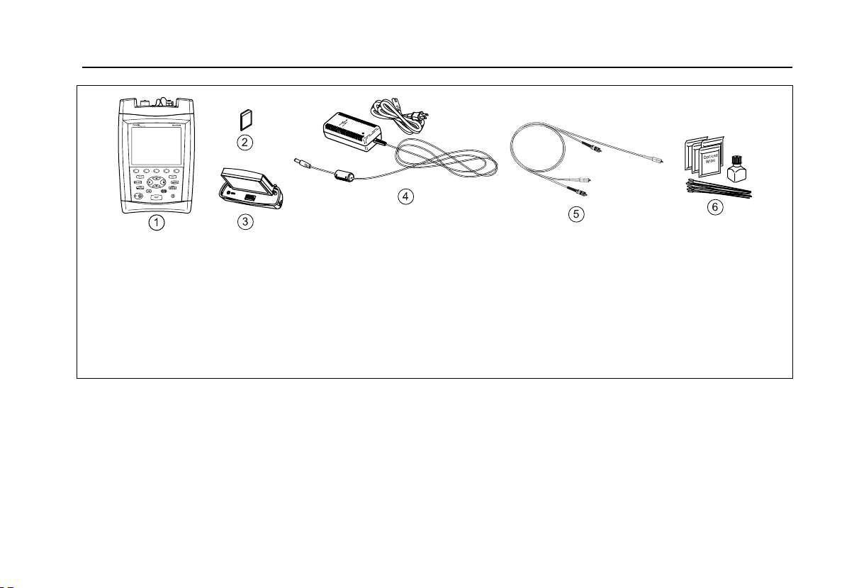
Using the Power Meter Option
ajt47f.eps
A Tester with OFTM-5611B, OFTM-5612B, or OFTM-5731,
or OFTM-5732 module. Match the connector adapter to
the connectors on the link or optical source to be
tested.
B Memory card (optional)
C Spare battery pack (optional)
Figure 35. Equipment for Power Meter Tests
D AC adapter with line cord (optional)
E One reference test cord cord. Match the fiber in the
link or the type usually connected to the source. Match
the tester's INPUT connector at one end and the link or
source connector at the other end.
F Fiber cleaning supplies
81
Page 92

OF-500 OptiFiber Certifying OTDR
Users Manual
Using the Power Meter
1 Select Power Meter mode: On the HOME screen, press
A Change Test; then select Power Meter. You do not
need to select a fiber type or test limit.
2 Clean the connectors on the reference test cord, source,
and link (if tested).
3 Use the reference test cord to connect the source to the
tester's INPUT port as shown in Figure 36.
4 Turn on the source.
5 Press
T; then select the appropriate wavelength.
Auto is used with SimpliFiber sources. See the online
help or Technical Reference Handbook for details.
6 To change the wavelength after starting the test, press
B Change Wavelength.
7 To save the results, press
ID; then press s again.
s, select or create a fiber
WCaution
If the tester shows an error because the power
reading is too high, immediately disconnect the
source from the tester. The tester is not designed
for measuring higher power levels, such as
produced by CATV, optical amplifiers, and cellular
systems.
82
Page 93

Using the Power Meter Option
Figure 36. Connections for Monitoring Optical Power
ajt11f.eps
83
Page 94

OF-500 OptiFiber Certifying OTDR
Users Manual
Overview of Memory Functions
You can save test results on a removable memory card or
in the tester’s internal memory. The tester can use
multimedia cards (MMC) or secure digital cards (SD).
To select a location for saving tests, press S then
select CURRENT FOLDER on the Job tab.
Tip: To avoid confusion regarding the location of test
records, save test results on a memory card
whenever possible.
You can save results from any fiber test, except the real
time trace.
Each test record can hold bi-directional results from each
type of test (except ChannelMap, which you run in just
one direction). The test direction assigned to saved results
is determined by the THIS END setting (in Setup) used
when the test was run.
You can save the last test you ran anytime before you run
another test. This excludes FiberInspector images and
power meter results, which you must save at the time of
viewing.
If SAVE WARNING on the System tab is enabled, the
tester warns you if you are about to do something that
will delete an unsaved test from temporary memory. The
unsaved test is retained in temporary memory even if you
turn off the tester or remove the battery pack.
Memory Capacity and Card Sizes Supported
The number of test records you can save in a given
amount of memory space depends on what you save in
the records. For example, records that include video probe
endface images take more memory than records without
images.
The maximum amount of internal memory available for
test results depends on the space taken by the tester’s
software and custom limits.
Notes
Memory card folders can store a maximum of
500 records each.
Loss/length tests in Smart Remote mode take up
two records
one for each fiber.
84
Page 95

About LinkWare and LinkWare Stats Software
OptiFiber software version 2.0 supports cards up to
4 gigabytes. Later versions may support larger cards.
Check the Fluke Networks Knowledge Base for the latest
information.
To see the memory space available, press F; then
select Memory Status. Press A to switch between the
memory card and internal memory status.
Clearing the Internal Memory
To clear the internal memory, which moves records to the
memory card, do the following:
1 On the System tab in Setup, set the CURRENT
FOLDER to the desired location on the memory card.
2 Press F; then select Empty Internal Memory.
About LinkWare and LinkWare Stats Software
LinkWare Cable Test Management software lets you
upload OptiFiber test records to PC, view test results, add
ANSI/TIA/EIA-606-A administration information to records,
and organize, customize, and print test reports.
Details about using LinkWare software are provided in
the LinkWare Getting Started Guide and the online help
available under Help on the LinkWare menu.
The LinkWare Stats Statistical Report option for LinkWare
software provides statistical analysis of cable test reports
and generates browsable, graphical reports. LinkWare
software includes a demo version of LinkWare Stats.
Contact Fluke Networks or visit the Fluke Networks
website for more information on LinkWare Stats.
85
Page 96

OF-500 OptiFiber Certifying OTDR
Users Manual
Maintenance
WWarning
To avoid possible fire, electric shock, personal
injury, or damage to the tester:
• Do not open the case. No user-serviceable parts
are inside.
• Replacing electrical parts yourself will void the
test tool's warranty and might compromise its
safety features.
• Use only specified replacement parts for user-
replaceable items.
• Use only Fluke Networks authorized service
centers.
WCaution
Replacing electrical parts yourself might void the
test tool's calibration and compromise its
accuracy. If the calibration is void, cable
manufacturers might not extend their warranty
to the cabling you install.
Updating the Tester’s Software
Keeping your tester’s software current gives you access to
new features and the latest test limits. Software updates
are available on the Fluke Networks website.
The software update procedure also lets you install or
remove languages. Additional languages for the tester
may be available with software updates.
To see the software version installed in your tester and
module exit to the HOME display; then press E Version
Info.
To determine if your tester needs a software update visit
the Fluke Networks website to see if an update is
available.
You can update an OptiFiber tester’s software with
LinkWare via a PC or with the tester’s software update
function via a memory card.
86
Page 97

Maintenance
WCaution
To avoid unexpected loss of power, connect the
ac adapter to the tester when updating the
software.
Note
Updating the software does not affect test
records saved in internal memory, but may affect
factory-installed fiber types or test limits.
You may install multiple languages; however,
adding languages decreases the internal memory
available for saving test results.
Changes to the update procedure may be posted
on the OptiFiber software page on the Fluke
Networks website.
Updating via the USB or Serial Port
1 Install the latest version of LinkWare software on
your PC. LinkWare is available on the Fluke Networks
website.
2 Download the OptiFiber update file (“upgrade.ofu”)
from the Fluke Networks website, or contact Fluke
Networks to get the update by other means. You can
access the software page at
www.flukenetworks.com/support. Save the file to
your hard drive.
3 Connect the tester’s serial or USB port to the PC.
Install a module in the OptiFiber mainframe, then
turn on the tester.
4 Select Utilities > OptiFiber Utilities > Software
Update from the LinkWare menu, locate and select
the .ofu (OptiFiber update) file; then click Open.
LinkWare makes initial choices on which software to
install based on the versions currently installed in the
mainframe and the module. Generally, you should
not change these choices except to select languages
to install or remove.
-continued-
87
Page 98

OF-500 OptiFiber Certifying OTDR
Users Manual
5 Click Start to start the update process.
6 The OptiFiber tester reboots after the update is
complete. To verify the update, press A Version
Info from the HOME screen.
7 If you have additional modules to update, install each
module in the tester and repeat steps 4, 5, and 6.
Updating via a Memory Card Created with LinkWare
WCaution
Do not use the PC's operating system to copy
the update file to a memory card. The file must
be unzipped first. Use LinkWare software to
create a memory card for updating the tester.
1 Install the latest version of LinkWare software on
your PC. LinkWare is available on the Fluke Networks
website.
2 Download the OptiFiber update file (“upgrade.ofu”)
from the Fluke Networks website, or contact Fluke
Networks to get the update by other means. You can
access the software page at
www.flukenetworks.com/support. Save the file to
your hard drive.
4 On the LinkWare menu select Utilities > OptiFiber
Utilities > Create Software Update MMC.
5 Locate and select the .ofu file you downloaded; then
click Open.
6 Locate and select the memory card drive; then click
OK. LinkWare unzips the update file and copies the
files to the memory card.
WCaution
If you remove the memory card from the MMC
reader before the files are completely copied the
Windows operating system may report an error
and OptiFiber shows the message “Bad update
file”. If this happens, repeat steps 4 through 6;
then leave the card in the reader for a minute or
so to ensure the files are completely copied.
7 Put the memory card into the OptiFiber tester.
8 Install a module in the OptiFiber mainframe, then
turn on the tester.
3 Put a memory card into the PC’s memory card drive.
88
Page 99

Maintenance
9 Press F on OptiFiber; then select Install Software
Update. The tester makes initial choices on which
software to install based on the versions currently
installed in the mainframe and the module.
Generally, you should not change these choices
except to select languages to install or remove.
10 Press E Start to start the update process.
11 The OptiFiber tester reboots after the update is
complete. To verify the update, press A Version
Info from the HOME screen.
12 If you have additional modules to update, insert each
module and repeat steps 9, 10, and 11.
Optical Connector Care
• Periodically clean and inspect the tester’s optical
connectors as described on page 27.
• Cover the connectors with the dust plugs when no
cable is connected.
• Periodically clean the dust plugs with a lint-free swab
or wipe and isopropyl alcohol.
Replacing Reference Test Cords and Launch Fibers
Choose replacement reference test cords and launch and
receive fibers that meet the following requirements:
• Core and cladding size: match the fiber to be tested
• Connector polish: UPC for reference test cords and
launch fibers
• Reference test cord length: minimum 2 m; maximum
5 m
• Launch and receive fiber length: 100 m minimum for
multimode; 130 m minimum for singlemode
To ensure optimum performance from your tester, get
replacement reference test cords and launch fibers from
Fluke Networks.
89
Page 100

OF-500 OptiFiber Certifying OTDR
Users Manual
Replacing the Battery
Replace the lithium ion battery pack when its life becomes
noticeably shorter. The battery is normally good for up to
400 charge/discharge cycles.
/Note
Dispose of the lithium ion battery pack in
accordance with local regulations.
An internal lithium battery maintains the tester’s clock
and other settings when you remove the battery pack.
This battery typically lasts about 5 years. When the battery
begins to fail, the tester will lose the current date and
time when you remove the battery pack. If the lithium
battery fails, send the tester to a Fluke Networks service
center for a replacement.
Cleaning
Clean the display with glass cleaner or isopropyl alcohol
and a soft, lint-free cloth. Clean the case with a soft cloth
dampened with water or water and a mild soap.
WCaution
To avoid damaging the display or the case, do
not use solvents or abrasive cleansers.
Storage
• Before storing the tester or an extra battery for an
extended period, charge the battery to between
70 % and 90 % of full charge (2 or 3 LEDs lit on the
battery’s gauge). Check the battery every 4 months
and recharge if necessary.
• Keep a battery attached to the tester during storage.
Removing the battery for long periods shortens the
life of the lithium battery that maintains the clock.
• See “Environmental and Regulatory Specifications”
on page 102 for storage temperatures.
90
Test Equipment Depot - 800.517.8431 - 99 Washington Street Melrose, MA 02176
FAX 781.665.0780 - TestEquipmentDepot.com
 Loading...