

Page 1
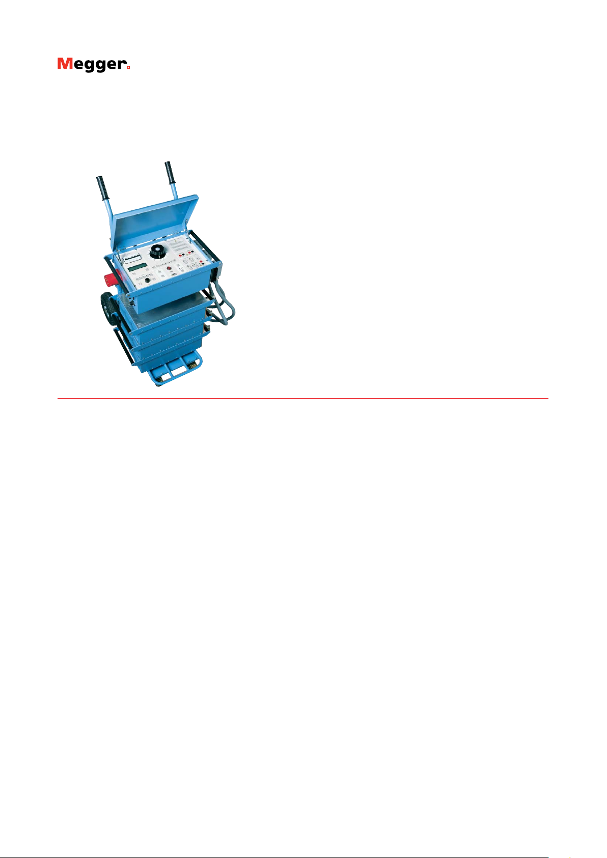
Primary Current Injection Test System
ODEN AT
Primary Current Injection Test System
▪
Most Advanced Primary Current Injection
Test System to simplify all types of
switchgear and CT commissioning, ground
grid, circuit breaker testing and more
▪
Modular design to permit optimal
user configuration of output current
vs. unit size
▪
Compact transport cart facilitates
portability into switchgear rooms
with limited space
▪
Unique I/30 function allows the current to
be pre-set using low current to prevent
test sample heating, thus eliminating
corruption of test result
ODEN AT
Description
This powerful test system is designed for primary injection testing
of protective relay equipment and circuit breakers. It is also used
to test the turns ratio of current transformers and for other
applications that require high variable currents.
The system consists of a control unit together with one, two or
three current units. There are three versions of the current unit: S,
X and H. The S and X current units are identical except that the X
unit has an additional 30/60 V output. The H unit is rated for even
higher current. This makes it possible to configure an ODEN AT
system in a suitable way. All parts are portable, and ODEN AT can
be quickly assembled and connected.
The control unit has many advanced features – a powerful
measurement section for example, that can display turns ratio as
well as time, voltage and current. A second measurement channel
can be used to measure an additional current or voltage. Current
transformer turns ratio, impedance, resistance, power, power
factor (cos φ) and phase angle are calculated and shown in the
display. Current and voltage can be presented as percentages
of nominal value. The fast-acting hold function freezes shortduration readings on the digital display when the voltage or contact
signal arrives at the stop input, the object under test interrupts the
current or injection is stopped
Application
Primary current injection testing and breaker testing
These tests require high currents and the ability to measure very
short duration, current flow. ODEN AT has been designed
especially to meet these needs. No extra contacts are needed to
measure the operating time of a low-voltage breaker. Testing stops
at the instant when the main breaker contacts open to interrupt
the current. Output current initiation is synchronized with the
currents zero-crossover point to ensure good repeatability and
minimized DC offset.
Testing current transformers
For turns ratio testing, the primary current and either the
secondary current or the turns ratio are displayed simultaneously.
Since the turns ratio is displayed directly as the nominal value
(1000/5 for example), no further calculation is needed. Burden of
secondary circuits can be measured and presented in VA.
Polarity testing
The currents phase displacement is shown, and the polarities of
the outputs are clearly marked.
Heat runs
ODEN AT is ideal for performing heat runs. Current can be
applied continuously or through programmable intervals. The
times can be shown in minutes and hours which facilitates longterm testing capability.
Automatic reclosers and sectionalizers
ODEN AT can also be set to test circuit breakers with reclosing
relays. Operating limits, partial times, total times and the number
of operations before lockout can be measured. User-selectable
reclosing sequences can be programmed for testing sectionalizers.
Testing integrity of ground grids and safety-ground devices
One way to test ground grids is by injecting current between a
reference ground and the ground to be tested and measuring the
voltage drop and the percentage of current flowing through the
ground grid. The type X current unit included with ODEN AT
is designed for this type of application. Personal safety grounds
must be tested at rated current, a task for which ODEN AT is well
suited.
Page 2
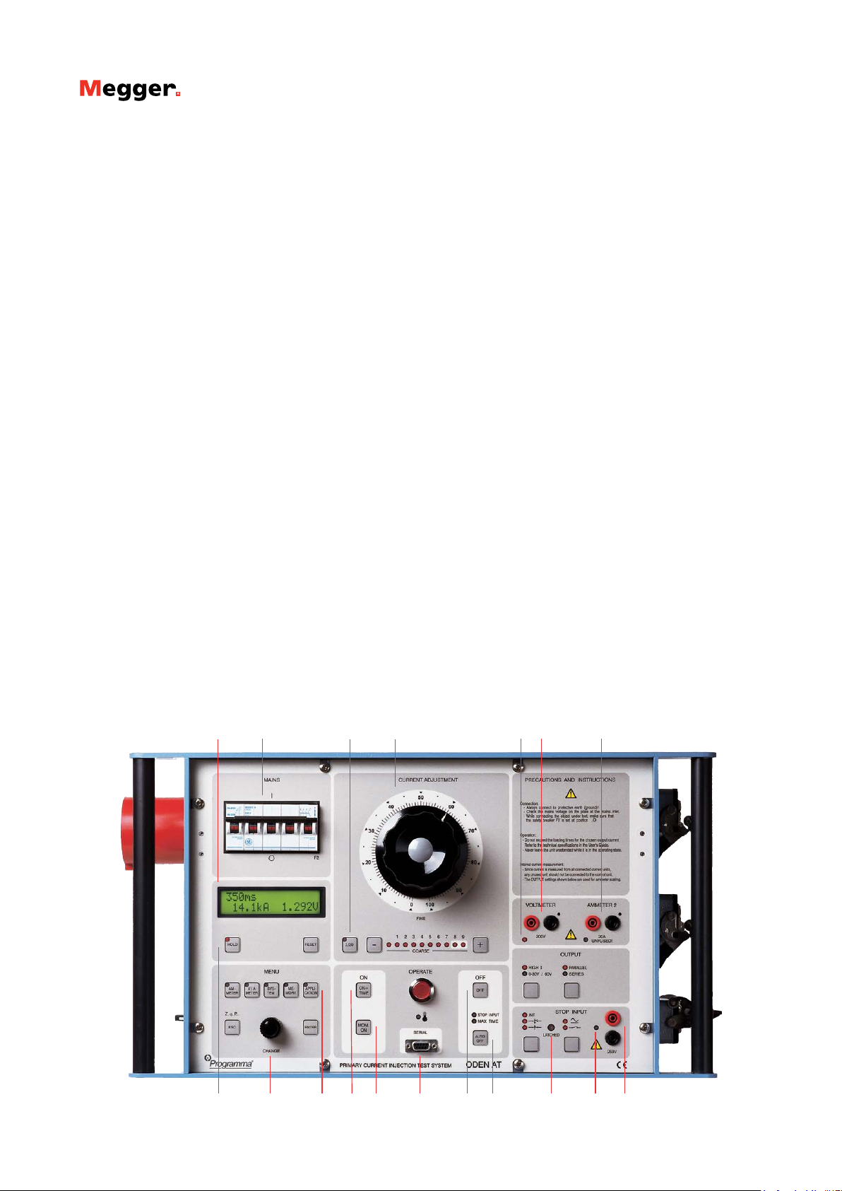
Features and Benefits
1. Display. The display presents time, output current, voltage,
current shown on ammeter 2 and phase angle. You can scroll
through entities Z, P, Q, R, X, S, power factor (cos φ) and I
max.
2. Miniature circuit breaker used for current output. Interrupts output current. Can also be actuated manually for safe
disconnection of load.
3. Current reduction button. Used during setting to reduce the
output current to 1/30. Useful in order to avoid for example
unintentional tripping and overheating.
4. Fine adjustment knob. Knob for fine adjustment of current
and +/- buttons for coarse adjustment.
5. Indicator lamps. Indicate whether ammeter 2 or the voltmeter is enabled.
6. Input for voltmeter. Used to measure voltage and for mi-
crohmmeter measurement.
7. Input for ammeter 2. Used to measure current in an external
circuit (in a current transformer´s secondary winding for example).
8. Hold function. This function freezes readings on the display.
9. Selection/setting (CHANGE) knob. Selects the desired
menu option (shown in the display window). Also used to
change numerical values.
10. Setting buttons. Personnel unfamiliar with ODEN AT can
use the pre-defined settings very effectively, while experienced
users can make their own basic settings.
• Ammeter. Used to set the main current-output ammeter. You
can select the desired range or select autoranging.
• V/A Meter. Toggles between the voltmeter and ammeter 2.
Also used to select the desired range or select autoranging.
• System. Used for general settings.
• Memory. Used to save or recall settings to or from the ten
ODEN AT memories. One of these memories contains the default (pre-defined) settings that are invoked when ODEN AT is
powered up.
ODEN AT
Primary Current Injection Test System
• Application. Used to invoke the desired measurement mode:
automatic recloser, sectionalizer or microhmmeter.
ODEN AT can also be set to generate pulse trains with user-selectable pulse and pause times.
11. Injection. Starts current injection and timing.
12. Momentary Injection. When this button is used, injection
continues only as long as it is pressed. Useful in order to avoid
for example overheating.
13. RS232 for computer. ODEN AT is equipped with a serial port
for communication with PC (for transfer of test data for example).
14. Manual shut-off. Injection and timing are stopped when this
button is pressed.
15. Automatic injection stop. Generation stops after a user-spec-
ified interval or when condition at the input is met. The diodes
show the selected OFF condition.
16. Stop-condition indicator. Indicates that a stop condition is
met, voltage or contact triggered.
17. Status indicator. Indicates if a contact connected to the input
is closed or if voltage is present.
18. Stop input. Used to freeze a reading or stop injection. Activat-
ed when current is interrupted by the object being tested, when
an external contact is actuated or when a voltage is applied or
removed.
1
2
3
4
12111098
13 14
5 7
15
6
16 17 18
Page 3

Specifications ODEN AT
Specifications are valid at nominal input voltage and an ambient
temperature of +25°C, (77°F). Specifications are subject to change
without notice.
System designation
An ODEN AT-system consists of a control unit and one, two or
three current units. There are three different versions of the current
units: S-unit (standard), X-unit (extra 30/60 V outlet) and H-unit
(high current). The system designation indicates the number and
version of current units included.
Example: ODEN AT/2X
2 = Number of current units
X = Version of current unit (S, X or H)
Environment
Application field The instrument is intended for use
in high-voltage substations and
industrial environments.
Temperature
Operating 0°C to +50°C (+32°F to +122°F)
Storage & transport -25°C to +55°C (-13°F to +127°F)
Humidity 5% – 95% RH, non-condensing
CE-marking
LVD 2006/95/EC
EMC 2004/108/EC
General
Mains voltage 240 / 400 V AC, 50 / 60 Hz
480 V AC / 60 Hz
Mains inlet IEC 60309-2, 63 A
Input current Output current x open circuit voltage
/ input voltage
Protection The output transformer has a built-in
thermal cut-out, and the primary
side is protected by a miniature
circuit breaker.
Dimensions
Control unit AT 570 x 310 x 230 mm
(22.4” x 12.2” x 9”)
Current unit S, X H 570 x 310 x 155 mm
(22.4” x 12.2” x 6”)
Complete with cart 690 x 350 x 860 mm
(27.2” x 13.8” x 33.9”)
Weight
Control unit AT 25 kg (55 lbs)
Current unit S 42 kg (92.6 lbs)
Current unit X 45 kg (99.3 lbs)
Current unit H 49 kg (108 lbs)
Cart 11 kg (24.3 lbs)
Display LCD
Available languages English, German, French, Spanish,
Swedish.
ODEN AT
Primary Current Injection Test System
Measurement section
Ammeters
Measurement method AC, true RMS
Inaccuracy 1% of range ±1 digit
Ammeter 1
Ranges 0 – 4800 A / 0 –15 kA
0 – 9600 A / 0 – 30 kA
0 – 960 A / 0 – 3 kA
Ammeter 2
Ranges 0 – 2.000 A / 0 – 20.00 A
Maximum current 20 A (The input is not protected by
a fuse)
Voltmeter
Measurement method AC, true RMS
Ranges 0 – 0.2 V, 0 – 2 V, 0 – 20 V,
0 – 200 V, AUTO
Inaccuracy 1% of range ±1 digit
Input resistance (Rin) 240 kΩ (range 0 – 200 V)
24 kΩ (other ranges)
Dielectric withstand 2.5 kV
Timer
Presentation In seconds, mains frequency cycles
or hours and minutes
Ranges 0.000 – 999.9 s
0 – 9999 cycles
0.001 s – 99 h 59 min
Inaccuracy ±(1 digit + 0.01% of value)
For the stop condition in INT-mode
1 ms shall be added to the specified
measurement error.
Stop input
Max. input voltage 250 V AC / 275 V DC
Phase angle
Range 0 – 359º
Resolution 1º
Inaccuracy ±2º (for voltage and current readings
that are higher than 10% of the
selected range)
Z, P, R, X, S, Q and power factor (cos φ)
For these measurements the result is calculated using U, I and
sometimes φ.
Imax
Stores highest current value that exists ≥100 ms
INT-level
Threshold indicating that current is interrupted. Can be set to
0.7% or 2.1% of Ammeter 1 range.
Page 4

Outputs
ODEN AT, 240 V mains voltage, 50 / 60 Hz
Open
circuit
voltage
Max. continuous
current
3)
Max. current, 3 mi-
3)
nutes
Max.
current,
3)
1 sec
ODEN AT/1S
6 V 1000 A 2000 A 7000 A
ODEN AT/2S
1)
2)
6 V 1680 A 3600 A 8000 A
12 V 1000 A 2000 A 4000 A
ODEN AT/3S
1)
2)
6 V 2500 A 5200 A 8000 A
18 V 840 A 170 0 A 2600 A
ODEN AT/1X
High current output
Output 0 – 30/60 V
30 V range 30 V 160 A 300 A 120 0 A
60 V range 60 V 80 A 150 A 600 A
6 V 1000 A 2000 A 7000 A
ODEN AT/2X
High current output
Output 0 – 30/60 V
30 V range
30 V range
60 V range
1)
2)
1)
2)
2)
6 V 1680 A 3600 A 8000 A
12 V 1000 A 2000 A 4000 A
30 V 320 A 600 A 1600 A
60 V 160 A 300 A 800 A
120 V 80 A 150 A 400 A
ODEN AT/3X
High current output
Output 0 – 30/60 V
30 V range
30 V range
60 V range
1)
2)
1)
2)
2)
6 V 2500 A 5200 A 8000 A
18 V 840 A 170 0 A 2600 A
30 V 480 A 900 A 1600 A
90 V 160 A 300 A 520 A
180 V 80 A 15 0 A 260 A
ODEN AT/1H
3.6 V 1250 A 2600 A 11 k A
ODEN AT/2H
1)
3.6 V 2500 A 5500 A 13 k A
2)
7.2 V 1250 A 2800 A 6500 A
ODEN AT/3H
1)
3.6 V 3800 A 8000 A 13 k A
2)
10.7 V 1250 A 2800 A 4300 A
ODEN AT
Primary Current Injection Test System
ODEN AT, 400 V mains voltage, 50 / 60 Hz
Open
circuit
voltage
ODEN AT/1S
ODEN AT/2S
1)
2)
ODEN AT/3S
1)
2)
ODEN AT/1X
High current output
Output 0 – 30/60 V
30 V range 30 V 160 A 300 A 120 0 A
60 V range 60 V 80 A 150 A 600 A
ODEN AT/2X
High current output
Output 0 – 30/60 V
30 V range
30 V range
60 V range
1)
2)
1)
2)
2)
ODEN AT/3X
High current output
Output 0 – 30/60 V
30 V range
30 V range
60 V range
1)
2)
1)
2)
2)
ODEN AT/1H
ODEN AT/2H
1)
2)
ODEN AT/3H
1)
2)
Max.
continuous
current
3)
Max. current, 3 mi-
3)
nutes
Max.
current,
1 sec
6 V 1000 A 2000 A 7000 A
6 V 1900 A 4000 A 13 kA
12 V 900 A 2000 A 6000 A
6 V 1900 A 4000 A 13 kA
18 V 600 A 14 00 A 4400 A
6 V 1000 A 2000 A 7000 A
6 V 1900 A 4000 A 13 kA
12 V 900 A 2000 A 6000 A
30 V 320 A 600 A 2500 A
60 V 160 A 300 A 120 0 A
120 V 80 A 150 A 600 A
6 V 1900 A 4000 A 13 kA
18 V 600 A 14 00 A 4400 A
30 V 380 A 850 A 2600 A
90 V 120 A 290 A 880 A
180 V 60 A 145 A 440 A
3.6 V 1250 A 260 0 A 11 kA
3.6 V 2500 A 5300 A 21 kA
7.2 V 1250 A 2500 A 10.9 kA
3.6 V 3800 A 7700 A 21.9 kA
10.7 V 1250 A 2600 A 7200 A
3)
Page 5

ODEN AT
Primary Current Injection Test System
ODEN AT, 480 V mains voltage, 60 Hz
Open
circuit
voltage
Max.
continuous
3)
current
Max. current, 3 mi-
3)
nutes
Max.
current,
1 sec
ODEN AT/1S
7.2 V 1000 A 2000 A 7000 A
ODEN AT/2S
1)
7.2 V 1900 A 4000 A 13 kA
2)
14.4 V 900 A 2000 A 6000 A
ODEN AT/3S
1)
7.2 V 1900 A 4000 A 13 kA
2)
21.6 V 600 A 140 0 A 4400 A
ODEN AT/1X
High current output
Output 0 – 30/60 V
30 V range 36 V 160 A 300 A 120 0 A
60 V range 72 V 80 A 150 A 600 A
7.2 V 1000 A 2000 A 7000 A
ODEN AT/2X
High current output
Output 0 – 30/60 V
30 V range
60 V range
60 V range
1)
7.2 V 1900 A 4000 A 13 kA
2)
14.4 V 900 A 2000 A 6000 A
1)
36 V 320 A 600 A 2500 A
1)
272 V 16 0 A 300 A 1200 A
2)
144 V 80 A 150 A 600 A
ODEN AT/3X
High current output
Output 0 – 30/60 V
30 V range
30 V range
60 V range
1)
7.2 V 1900 A 4000 A 13 kA
2)
21.6 V 600 A 140 0 A 4400 A
1)
36 V 380 A 850 A 2600 A
2)
108 V 120 A 290 A 880 A
2)
216 V 60 A 145 A 440 A
ODEN AT/1H
4.3 V 12 50 A 2600 A 11 k A
ODEN AT/2H
1)
4.3 V 2500 A 5300 A 21 kA
2)
8.7 V 1250 A 2500 A 10.9 kA
ODEN AT/3H
1)
4.3 V 3800 A 7700 A 21.9 kA
2)
13.0 V 1250 A 2600 A 7200 A
High current output - ODEN AT systems for 240 V, 50 Hz
3)
Output voltage* (V)
Current (kA)
High current output - ODEN AT systems for 400 V, 50 Hz
Output voltage* (V)
Current (kA)
High current output - ODEN AT systems for 480 V, 60 Hz
1) Current units connected in parallel
2) Current units connected in series
3) Maximum possible current is also limited by the impedance in the test circuit. The
current value can not exceed output voltage / impedance value.
Output voltage* (V)
Current (kA)
S or X units
H units
p = units in parallel, s = units in series
*) Voltage between output terminals
Page 6

Optional accessories
ODEN AT
Primary Current Injection Test System
HCP2000 — High Current Probe
The high current probe, HCP2000, is a tool that makes it
possible to test Molded Case Circuit Breakers (MCCB), without
removing/uninstalling the circuit breaker. The high current
probe operates up to 2000A trip current.
Current transformer switchbox
The Current Transformer (CT) Switchbox for ODEN AT is
a tool that is used to facilitate CT testing. The secondary windings on the CT are connected to the CT Switchbox inputs and
the CT Switchbox output is connected to ODEN AT Ammeter
2 terminals. The switch on the CT Switchbox is used to select
which secondary winding on the CT that should be measured.
The windings that aren’t measured are short-circuited. The CT
Switchbox can handle up to 5 secondary windings.
High current serial bar
For serial connecting of ODEN current units.
Multi-cable high current cable sets
Low-impedance multi-cable sets for higher output current.
Available with 2, 3, 4 or 6 parallel cables, and in lengths of 0.5,
1.0, 1.5 or 2 meters.
Cable sets
See Ordering Information.
Input power adapter 240/400V
Used to run a 400 V ODEN AT at 240 V.
High current parallel bars
The parallel bars can be used when up to three current units
are connected in parallel.
Page 7

Ordering information
ODEN AT
Primary Current Injection Test System
Item Art.No.
A cart (Art.No. 50- 00092) is always included with
purchase of a complete ODEN system. The cable
set(s) for connection to the object under test must
however be stated as a separate item in the order.
High current serial bar for connecting current units
in series is included with purchase of two current
units.
ODEN AT/ 1S
240 V Mains voltage
400 V Mains voltage
480 V (60 Hz) Mains voltage
BH-6 2411
BH-6 4011
BH-6 4811
ODEN AT/2S
240 V Mains voltage
400 V Mains voltage
480 V (60 Hz) Mains voltage
BH -62412
BH -64 012
BH -64 812
ODEN AT/ 3S
240 V Mains voltage
400 V Mains voltage
480 V (60 Hz) Mains voltage
BH -62413
BH -64 013
BH -64 813
ODEN AT/ 1X
240 V Mains voltage
400 V Mains voltage
480 V (60 Hz) Mains voltage
BH -62421
BH -6 4021
BH -6 4821
ODEN AT/ 2X
240 V Mains voltage
400 V Mains voltage
480 V (60 Hz) Mains voltage
BH-62422
BH-64022
BH-64822
ODEN AT/ 3X
240 V Mains voltage
400 V Mains voltage
480 V (60 Hz) Mains voltage
BH-62423
BH-64023
BH-64823
ODEN AT/ 1H
240 V Mains voltage
400 V Mains voltage
480 V (60 Hz) Mains voltage
BH-62431
BH-64031
BH-64831
ODEN AT/ 2H
240 V Mains voltage
400 V Mains voltage
480 V (60 Hz) Mains voltage
BH-62432
BH- 64032
BH- 64832
ODEN AT/ 3H
240 V Mains voltage
400 V Mains voltage
480 V (60 Hz) Mains voltage
BH-62433
BH- 64033
BH- 64833
Item
Art.No.
Optional accessories
HCP2000
Current Transformer Switchbox
High Current Serial Bar
AA-90165
BH -9013 0
BH-90102
High Current Parallel Bars, 2 pcs
Weight: 3 kg
BH -90171
Mains Adapter 240/400V
Note: Can only be used together with an ODEN AT
prepared for this feature. Contact Megger Sweden.
BH -90120
ODEN-Select
Software tool for finding the best ODEN AT configuration. Free-ware, can be downloaded from the
Megger ftp server.
Multi-cable high current cable sets
Length Impedance
(Twisted-pair cables)
2
2
2
2
2
(2x120)
GA -12205
GA -12210
GA -12215
GA-12220
(3x120)
GA -123 05
GA -12310
GA -12315
GA -12320
(4x120)
GA -124 05
GA -12410
GA -12415
GA -12420
(6x120)
GA -126 05
GA -12610
GA -12615
GA -12620
2
Cross section area: 240 mm
2 x 0.5 m (1.6 ft) 0.21 mΩ
2 x 1 m (3.3 ft) 0.32 mΩ
2 x 1.5 m (4.9 ft) 0.42 mΩ
2 x 2 m (6.6 ft) 0.53 mΩ
Cross section area: 360 mm
2 x 0.5 m (1.6 ft) 0.18 mΩ
2 x 1 m (3.3 ft) 0.25 mΩ
2 x 1.5 m (4.9 ft) 0.32 mΩ
2 x 2 m (6.6 ft) 0.39 mΩ
Cross section area: 480 mm
2 x 0.5 m (1.6 ft) 0.16 mΩ
2 x 1 m (3.3 ft) 0.21 m Ω
2 x 1.5 m (4.9 ft) 0. 27 mΩ
2 x 2 m (6.6 ft) 0.32 mΩ
Cross section area: 720 mm
2 x 0.5 m (1.6 ft) 0.14 mΩ
2 x 1 m (3.3 ft) 0.18 mΩ
2 x 1.5 m (4.9 ft) 0.21 mΩ
2 x 2 m (6.56 ft) 0.25 mΩ
Cable set, 2 x 5 m (16 ft), 120 mm
Cross section area: 120 mm
Weight: 15.2 kg (33.5 lbs)
Impedance: 2.2 mΩ GA -12052
Cable set, 2 x 5 m (16 ft), 25 mm
2
Cross section area: 25 mm2
For the 30/60 V output of current unit X.
Weight: 4 kg (8.8 lbs) GA-02052
SWEDEN
Megger Sweden AB
Eldarvägen 4, Box 2970
SE-187 29 TÄBY
T +46 8 510 195 00
F +46 8 510 195 95
E seinfo@megger.com
UK
Archcliffe Road Dover
CT17 9EN England
T +44 (0) 1304 502101
F +44 (0) 1304 207342
Other Technical Sales Offices
Dallas USA, Norristown USA,
Toronto CANADA, Trappes FRANCE,
Oberursel GERMANY, Johannesburg
SOUTH AFRICA, Kingdom of BAHRAIN
Mumbai INDIA, Chonburi THAILAND
Sydney AUSTRALIA
Registered to ISO 9001 and 14001
Subject to change without notice.
Art.No. ZI-BH02E • Doc. BH0456DE • 2012
ODEN-AT_DS_en_V04
www.megger.com
Megger is a registered trademark
 Loading...