

Page 1
Page 2
I
nterference Simulator System
NSG 600
This very versatile system provides for the simulation
of the most varied transient conditions which occur in
AC and DC mains, but also has facilities to permit the
application of transients without supply voltage.
The system consists of a main frame and various plugi
n units which generate the specific disturbances.
The basic equipment contains:
- Main frame unit with centralized power supply and
control for 1 to 4 plug-in units.
- Microprocessor controlled function keys and LCD
display.
- Connection to the unit under test and pulse output.
- RS 232-C interface for computerized remote control.
The system and plug-in unit functions are programmed on the control panel and remain stored for
l
ater recall when required.
Standard functions are preprogrammed ex works and
may be recalled or modified by use of the front panel
key controls. The LCD display supports the dialogue
with the user when setting the test sequences and
shows the device status continuously.
The power electronics of the various test modules
(
mains failures, interference pulse generators etc) are
i
ncorporated in the plug-in units. These units are
i
nserted from the rear into the main frame and are
automatically connected to the control electronics and
to the connector for the equipment under test. The
plug-in units have facilities to provide connections for
additional devices such as variac, artificial mains,
3-phase extensions etc.
The modular construction of the NSG 600 test system
allows for the assembly of individual test systems.
With further plug-in units and options it promises to
meet most future user requirements for interference
simulation.
Complete and complex test sequences, according to
various standards, may be run without changing test
generators or without disrupting the power to the
equipment under test.
A serial RS 232-C interface permits control of all system functions by means of an external computer. The
computer also allows the dynamic parametering of the
test procedure and the automatic logging of test processes and results, including failures of the unit under
test.
The NSG 600 system is also especially suitable for
automatic final tests.
I
n critical cases an opto-link option may be used to
ensure undisturbed operation of the computer connected to the remote socket.
By use of a converter remote control is also possible
via a GPIB (IEEE 488) Controller.
Examples of software and test programmes for MS-
DOS are available to help users.
Plug-in units
NSG 603 Simulator for AC/DC mains voltage fluctu-
ations and interruptions.
NSG 622
Additional types of plug -in units for tests and require-
ments according to various standards (Burst, Mil, etc)
are under development.
Simulator for fast interference pulses and
medium energy interference pulses.
Page 3
NSG 600
Technical Data
System supply
- 110/220 V (± 20%) 50/60 Hz
switchable on main frame,
connection via 6 A equipment plug
EUT supply
- 15 + 264 VAC
15 + 65 Hz/16A max
65 + 500 Hz/6 A max
- 5 + 50 VDC/16A max
- Connection via 16A equipment plug
- Decoupled against generated transient
pulses being fed onto the supply
network
Test supply output
- Supply voltage with the selected inter-
ference superimposed via the mains
socket (country specific)
and safety banana plugs
HV pulse output
- Pulses without supply voltage:
Fischer 5 kV coaxial socket
(e. g. for data line coupling devices)
Remote control
- RS 232-C interface with supply for
opto-link: Cannon 25 pol.
Plug-in outfit
- 1 to 4 pieces
Dimensions
- Width 448 mm
(
mounting in 19' rack possible)
Height 266 mm
Depth 455 mm (without handles)
Weight approx 20 kg
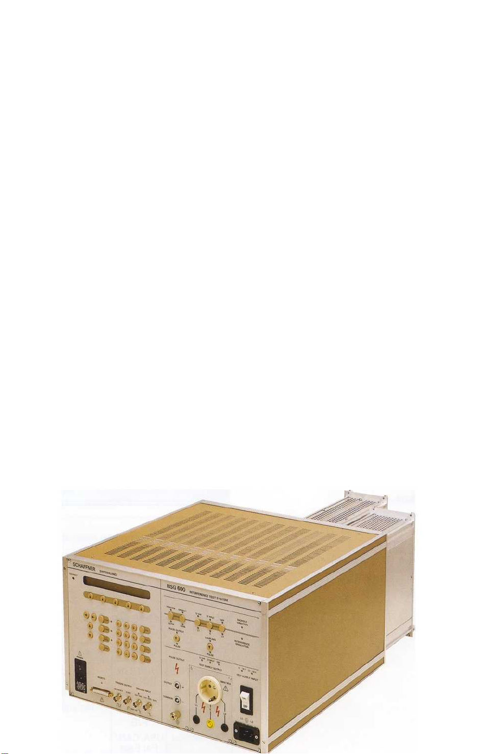
Basic equipment NSG 600
Page 4

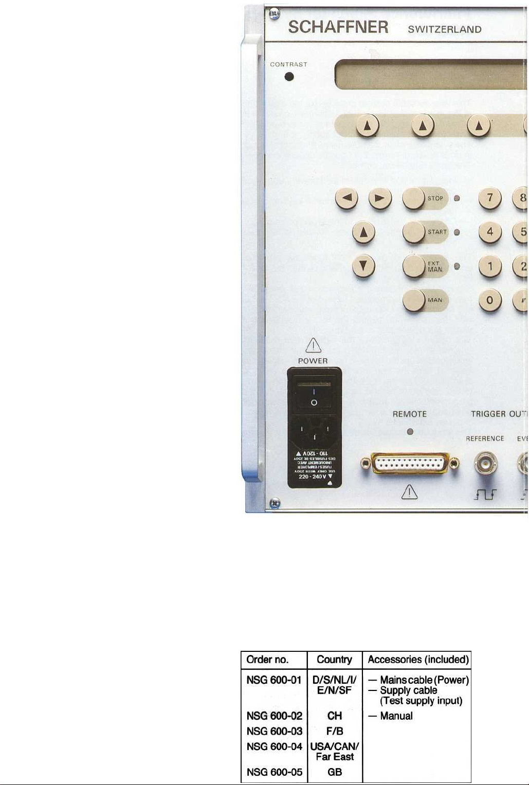
Accessories
Order no.
402-251
402-227
431-958
402-089
156-155
(not included)
Measuring adapter 1000 : 1 with connections for oscilloscope (For other
types than NSG 600-01 additionally
adapter 402-270 is necessary)
Safety banana plug set
1
pair coaxial cables, 0.3 m, with
Fischer HV plug
1
pair cables, 1 m, with HV plugs and
banana plugs 4 mm
HV plug for cable 0 4.3 mm
I
NA 302
I
NA 303
I
NA 304
I
nterface RS 232-C - - IEEE 488
GPIB
Opto-link option
10 m, with power supply 230 VAC
Opto-link
10 m, with power supply 110 VAC
option
Page 5

With the NSG 603 plug-in unit interruptions and voltage fluctuations on AC and DC mains can be simul
ated in accordance with generally known standards.
Thanks to the use of state of the art semiconductor
technology, power-MOS-FETs and microprocessor
control, supply dropouts can be inserted at any
desired phase angle. The respective times for repetition, drop out time and phase displacement can be
programmed by the decimal keyboard and LCD display on the main frame or via remote control equip-
ment.
For voltage variations a second voltage source (e. ~.
motorized Variac, electronic AC-source, DC supp y
equipment) is connected on the rear side. A control
output 0 + 10 VDC controls the additional source
adjusting the outputs to the desired value, programmed on the main frame-unit.
Provision has been made on this equipment for the
connection of a future 3-phase extension and an
external switch with high breaking capacity.
The system has automatic overload protection to prevent damage to the NSG 600 from failure in the equip-
ment under test.
Page 6

Page 7

Page 8

 Loading...