

Page 1
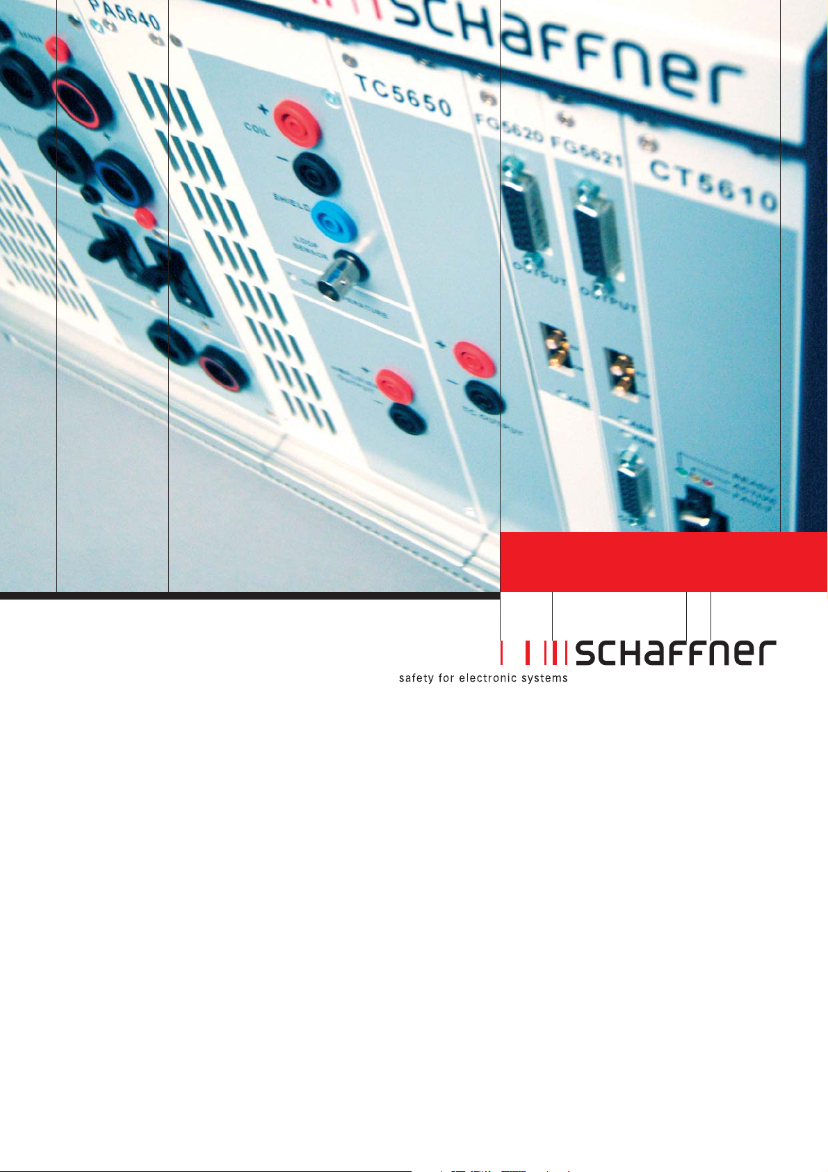
Test Systems
NSG 5600
Complex voltage variations, magnetic field test,
sinusoidal burst
Page 2
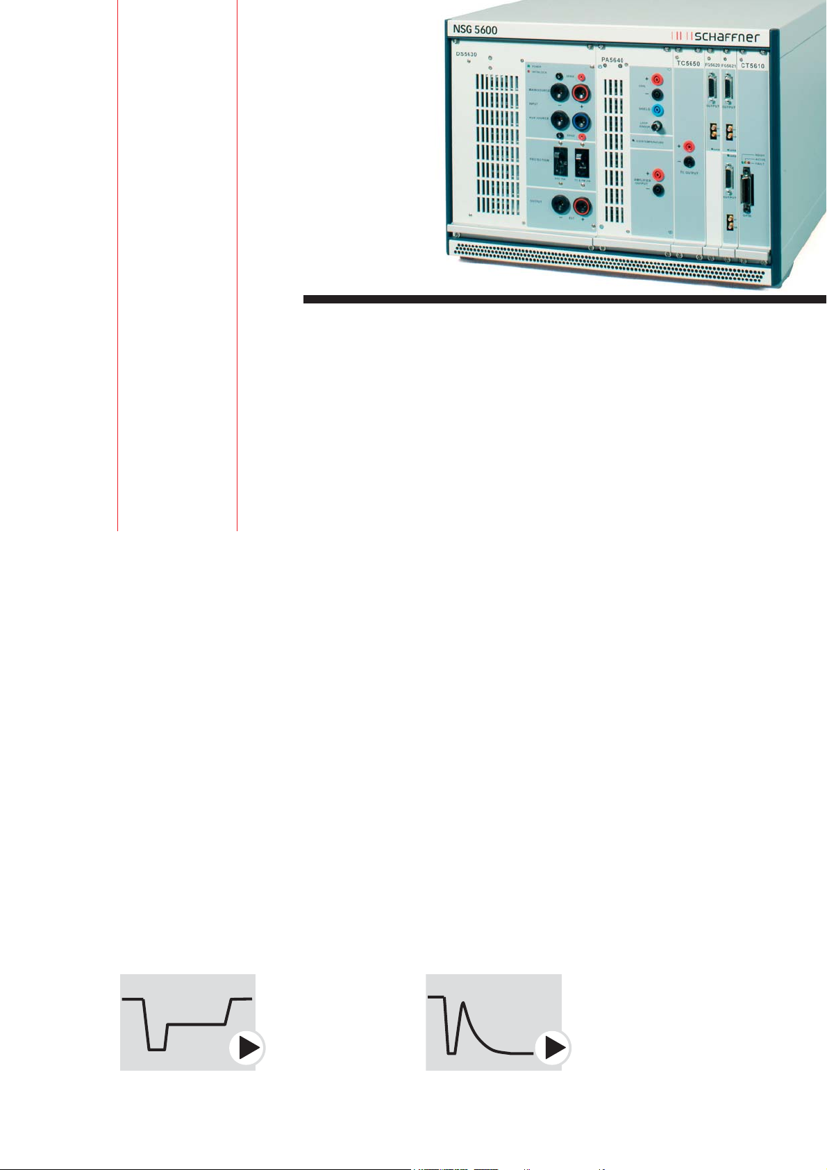
NSG 5600. Designed to be used either alone or in
combination with a NSG 5500 system, the NSG 5600
is designed to simulate events that include voltage
dropouts, sinusoidal noise and other events super-
imposed on the automotive battery: Dips and drops,
and ISO and SAE pulse 2b and pulse 4 and other
starting profiles. The NSG 5600 is the leader in syn-
chronized voltage variations, such as power cycling
tests (on up to four FGs) as required by various stan-
dards such as CI 230 defined in the Ford ES-XW7T-
1A278-AB and AC standards. Additionally, the
NSG 5600 may be configured for magnetic field
immunity testing. The basic NSG 5600 includes one
FG 5620 but additional capability may be added
using any of the modules on the following pages.
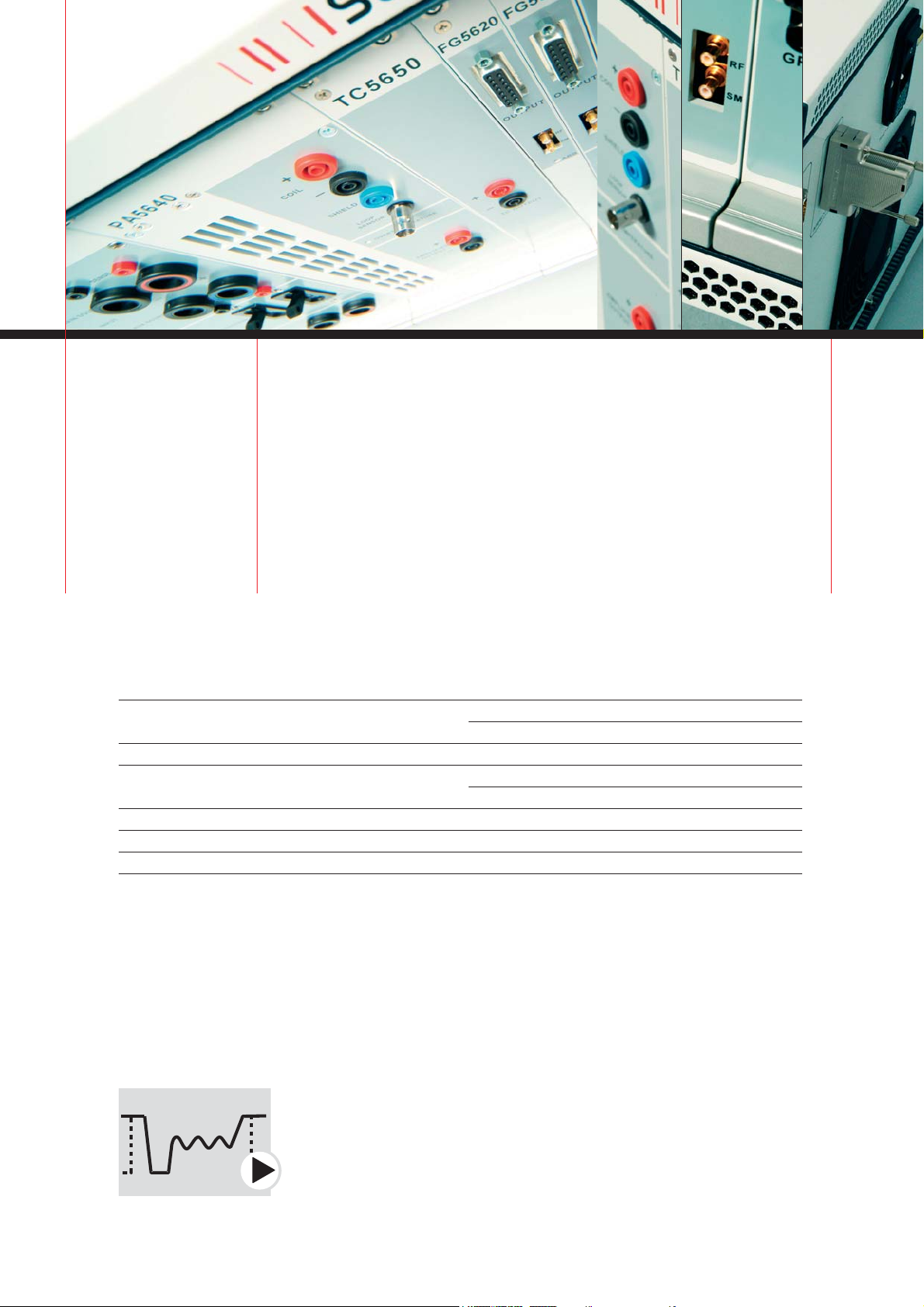
NSG 5600 concept. Schaffner continues to utilize its
well accepted modular concept of a 19” basic chassis
containing all the power supply components and,
if required, the sinusoidal burst-transformer, the
control and signal bus boards as well as the com-
mon inputs and outputs for the safety circuits and
signals for the expanded control and monitoring of
the test. The CAN-bus, already well known in auto-
motive technology circles, is used as the system bus.
Therefore, as with the complimentary NSG 5500,
Schaffner’s modular concept, new capabilities can
be quickly implemented. Modular and flexible test
systems equal protection of investment for the user.
Schaffner offers rack-mounted solutions with suit-
able internal cabling and mains control panel as
accessories, configured to the user’s needs.
Utilizing the only automotive EMC specific synchronized, multi-channel function
generator (FG) in the world, the software integrates the various system com-
ponents seamlessly into the overall system concept with uniform operating pro-
cedures and user guidance together with a comprehensive test result reporting
facility.
NSG 5600
Complex voltage variations,
magnetic field test, sinusoidal burst
Page 3
Technical specifications NSG 5600
AC operating voltage & frequency ranges:
Dimensions:
Interface:
Rack weight:
Safety interlocks:
Auxiliary input signals:
Auxiliary output signals:
100V / 120V / 220V / 240V, 47 - 63Hz
19” desktop housing (rack mountable),
height 330mm (13”), depth 510mm (20”)
IEEE 488 (GPIB)
NSG 5601: 18kg (39.7lbs)
NSG 5602: 26kg (57.4lbs)
Yes
DUT FAIL / EXT / PAUSE / RESUME
CRO-TRIG / TEST-END
Combined with a power amplifier/battery simulator, the NSG 5600 represents the
most powerful solution for battery voltage variation simulation.
Page 4
The function generator FG 5620 is used universally
throughout the NSG 5600 for the control of DC
sources and power amplifiers. The AutoStar
TM
soft-
ware defines the necessary voltage/frequency con-
ditions. The controller converts this information
into algorithms for the FG (function generator),
which creates an image of the requirements in its
own memory and then generates the output signals
for the addressed power modules during the test
run. All the requisite waveforms can be created
numerically from the basic functions or by loading
a Clone
TM
, e.g. a memory map of values from a
storage oscilloscope or other external application,
the FG also generates waveforms that can be diffi-
cult to describe mathematically or where real-world
events need to be simulated. AutoStar supports any
external application that can output an ASCII list,
MathCAD or Microsoft Excel, for example.
Every card incorporates a second channel for the
control of a further source with a programmable,
steady state voltage as well as an output for setting
the current limiting of the source. The main output
signal consists of analog voltage of -10 to +10V – a
standard that is used by the majority of voltage
sources. Limits are only imposed by the sources used
for a particular application. For this reason, Schaffner
offers a full range of standard-compliant battery
simulators.
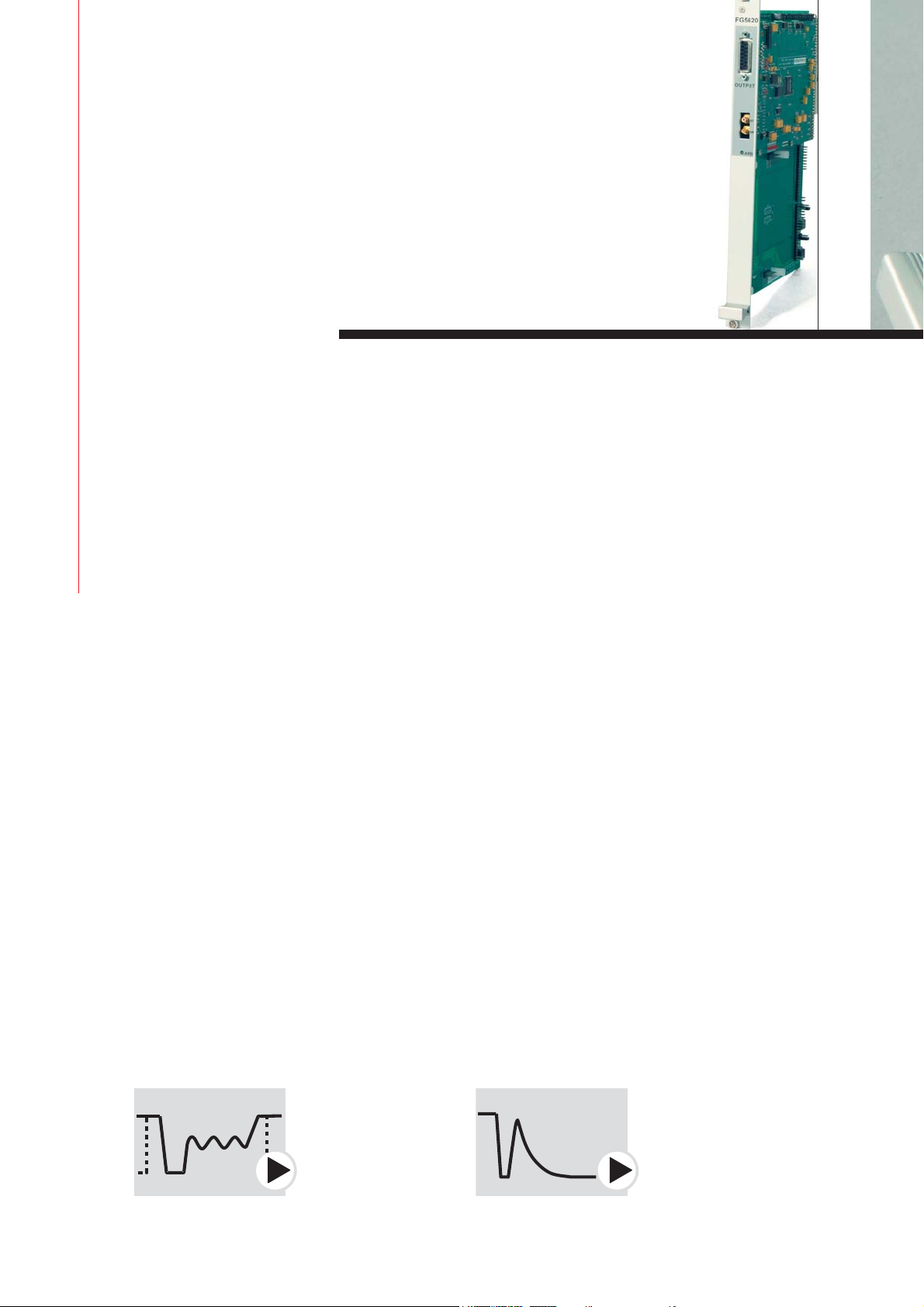
The FG 5620 is a module equipped with a function
generator board. A second board can be added sub-
sequently at any time. The FG 5621 is delivered
equipped with two function generators.
Two of these modules can be used in a system, i.e.
up to four function generators are available to con-
trol the relevant number of sources. All the gener-
ators used are programmed separately and run
synchronously based on a master-slave relationship.
FG 5620
Function generator
Single-click programming plus the powerful CloneTMfunction make this the
most powerful automotive EMC function generator in the world.
Page 5

Technical specifications FG 5620
Basic functions:
Ramping capabilities:
Output voltage:
Resolution:
Accuracy:
Impedance:
Short circuit protection:
Number of segments per waveform:
Frequency range:
Frequency resolution:
Amplitude & offset ramping:
Frequency ramping sine / square / triangle:
Phase angle:
Rectification:
Test duration:
Clone
TM
memory for oscilloscope capture or
imported Excel or text files:
DC voltage, sine, square, triangle, ramp and
exponential function
Amplitude, frequency, DC offset
-10V - +10V
10mV
±10mV
10Ω
Yes
1 to 100
DC -320kHz
0.01Hz
Linear
Linear, log (base 10)
0 - 360° in 15° steps
None, positive, negative
1ms - 100h, 1 - 9,999 cycles
80k samples
All the requisite waveforms can be easily created from the basic functions or
by loading a memory map of values.
Page 6
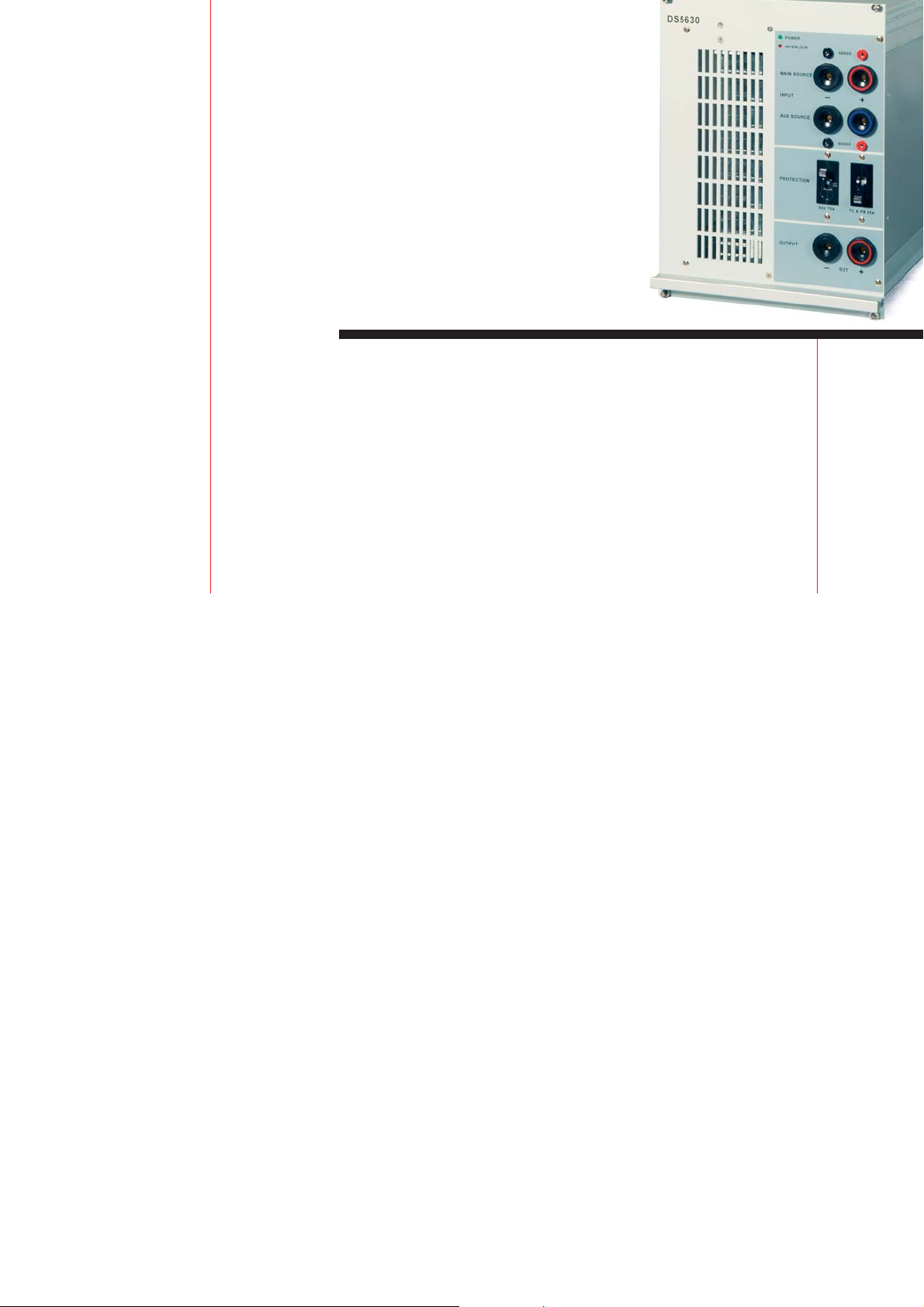
The DS 5630 switches the voltage source through to
the EUT connection under program-control. The
primary input and the auxiliary connection enable
two sources to be used. The DC switching capacity
of 70V/75A is capable of coping with high power
requirements and is ready for the 42V era.
The selectable switching conditions are:
Output (EUT)
Q
to primary source
Q
to auxiliary source
Q
switched off (open)
Q
dip and drop from primary to auxiliary source
and back again
Q
to primary source with 2Ω extra impedance
(SAE J 1113-11 pulse 2b)
Due to the rapid switching times, the requirements
of every standard that calls for drop-outs and volt-
age jumps in the µs range can be fulfilled by using
a battery simulator and an auxiliary source. The
DS 5630 also acts as the DC input for the transformer
coupled sine wave noise or for magnetic field im-
munity tests when high field strengths are required.
DS 5630
Dips and drops switch
A powerful electronic switch for fast dips and drops applications.
Page 7

Technical specifications DS 5630
Primary input voltage:
Current:
Voltage drop:
Auxiliary input voltage:
Current:
Switch time ON:
OFF:
SAE pulse 2 output impedance:
Overvoltage protection:
Overcurrent protection:
-4V to 70V
0 - 75A
1Vmax @ 75A
0 - 70V
0 - 75A
0.2 - 1.5µs
0.5 - 1.5µs
(13.5V - 0V with 1kΩ load)
2Ω
75V
>75A
Page 8
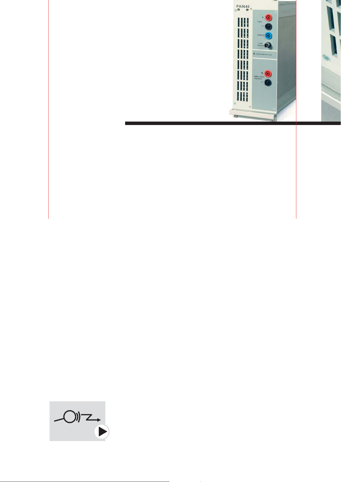
Matching the capabilities of the FG 5620, up to
±15V and 5A can be delivered by the power amplifier
module, which means that for many applications –
namely for small 12V component and subassembly
testing – the use of an external battery simulator is
unnecessary. The frequency range and bipolarity
ensure that the module will find a wide range of
applications. The EUT current can be measured and
a program-controlled current limit can be specified.
The PA 5640 also serves as a power driver for the
electromagnetic coils used in magnetic field tests
and as an amplifier for conducted sine wave tests.
Separate current measurements for the two types of
tests ensure correct control of the test conditions.
Magnetic field tests. The NSG 5600 configuration is
expanded by the addition of magnetic field antennae
for the execution of magnetic field tests. Either
simple current loops or Helmholtz coils are used de-
pending on the relevant test standard. The PA 5640
is equipped with a control input for the connection
of a magnetic field measuring sensor for the precise
regulation of the generated field.
PA 5640
Power amplifier
The bandwidth and bipolar operation of this amplifier ensure that it will find
a wide range of applications.
Page 9

Technical specifications PA 5640
Operating modes:
Output voltage:
Resolution:
Accuracy:
Current:
Impedance:
Current limit range:
Resolution:
Accuracy:
Frequency range:
Resolution:
Accuracy:
Short circuit protection:
Continuous voltage / Continuous current
-15 to +15V
0.1V
±0.1V
-5 - +5A
0.5Ω
0.1 - 5A
0.1A
±0.1A
DC - 320kHz
±(0.1% + 1Hz)
±(0.1% + 1Hz)
Yes
Page 10

Conducted sinusoidal interference simulations
are described in various standards with differing
conditions pertaining to them. The TC 5650
module contains the necessary circuitry for pulse
superimposition, selectable impedances and the
connection mechanism to the transformer as re-
quired by SAE J 1113-11 etc.
TC 5650
Transformer coupled conducted sine waves
The perfect solution for transformer coupled sine wave noise simulations.
Page 11

Technical specifications TC 5650
Transformer frequency:
Resolution:
Accuracy:
Current:
Source impedance:
Battery DC current:
Transformer turns ratio:
Connection:
Bypass capacitor, switchable:
MCB protection:
30 - 250kHz
1Hz
±(1% + 1Hz)
-5 - +5A
<0.5Ω
0 - 25A
2 : 1
Positive or negative lead
100µF
25A
Supports numerous features required by sine wave noise simulation standards.
Page 12

To find your local partner within
Schaffner’s global network, please go to
www.schaffner.com
690-820A April 2005
Printed in Germany
© 2005 Schaffner Electrotest GmbH.
Specifications subject to change without
notice. All trademarks recognized.
Schaffner is an ISO-registered company.
Its products are designed and manufactured under the strict quality and environmental requirements of the ISO 9001 and
ISO 14001 standards.
This document has been carefully checked.
However, Schaffner does not assume any
liability for errors or inaccuracies.
Headquarters
Schaffner EMV AG
CH-4542 Luterbach, Switzerland
T +41 32 681 66 26
F +41 32 681 66 41
sales@schaffner.com
www.schaffner.com
China
Schaffner Beijing Liaison Office
T +86 10 6510 1761
chinasales@schaffner.com
France
Schaffner EMC S.A.S.
T +33 1 34 34 30 60
francesales@schaffner.com
Germany
Schaffner Electrotest GmbH
T +49 9342 87 50
desales@schaffner.com
Italy
Schaffner Electrotest S.r.l.
T +39 030 71 00 29 9
tsitalysales@schaffner.com
Japan
Schaffner EMC K.K.
T +81 3 5456 0180
japansales@schaffner.com
Singapore
Schaffner EMC Pte Ltd.
T +65 6377 3283
singaporesales@schaffner.com
Switzerland
Schaffner EMV AG
T +41 32 681 66 26
sales@schaffner.ch
UK
Schaffner Ltd.
T +44 118 9770070
uksales@schaffner.com
USA
Schaffner EMC Inc.
T +1 732 225 9533
Toll free 0800 367 5566
usasales@schaffner.com
 Loading...