

Page 1
NI Educational Laboratory Virtual Instrumentation Suite (NI ELVIS)
NI ELVIS
• Design and prototyping
p
latform for circuits, control,
instrumentation, communication,
and embedded experiments
•
USB plug-and-play interface
• Virtual instrumentation suite
• Oscilloscope, digital multimeter
(DMM), function generator, variable
power supply, bode analyzer, arbitrary
waveform generator, dynamic signal
analyzer (DSA), voltage/current
analyzer with LabVIEW source code
• Completely open and customizable
in LabVIEW graphical
programming environment
Tight integration with Electronics
•
Workbench Multisim and MultiMCU
• Express VIs for point-and-click
configuration of customized
uments in LabVIEW
instr
and SignalExpress
Workstation Features
• Short-circuit and high-voltage protection
with resettable fuse board
• Variable power supplies, manual or
programmatic control
• Function generator, manual or
programmatic control
•
±15 and +5 V supply
• BNC inputs for DMM and scope
• Detachable, customizable
prototyping board
• Affordable for student ownership
• Designed to fit in a 2 or 3-ring binder
Companion Products
• Controls – Quanser control boards
• Microcontroller – Freescale MPU
• Embedded/DSP – Analog Devices BF537
• Sensors – Vernier sensor adapters
for NI ELVIS
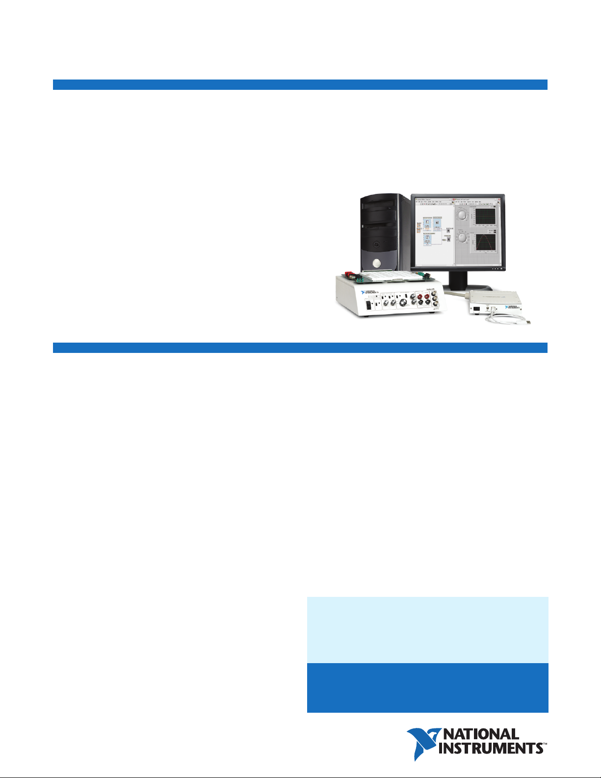
Overview
NI ELVIS is the leading platform for teaching concepts in areas such as
instrumentation, circuits, control, communication, and embedded design
in a hands-on fashion. With its integrated suite of the 12 most commonly
used instruments in a compact, rugged, laboratory-friendly package, and
now with a USB interface, NI ELVIS delivers a complete design and
prototyping platform. Professors can use it for freshman to senior-level
classes to help students learn concepts in a hands-on manner.
Powered by LabVIEW
The new NI ELVIS is now completely customizable with the premier
measurement and control software, National Instruments LabVIEW.
It includes Express VIs that provide point-and-click configuration
capabilities for the individual instruments, which makes building
customizable instruments very easy. You also can use the new
NI ELVIS with National Instr
is based on LabVIEW, for quickly designing measurement setups.
Multidisciplinar
NI ELVIS provides a multidisciplinary teaching platform for
hands-on learning in areas such as measurements, circuits, control,
communication, and microprocessor and embedded design. Several
industry and education leaders in these areas now support NI ELVIS.
Quanser offers NI EL
a microprocessor boar
uments SignalExpress software, which
y Teaching Platform
VIS-compatible boar
d for education that you can use with NI EL
ds for controls. Freescale has
VIS.
Analog Devices (ADI) includes the NI ELVIS connector on its ADI BF537
board to conduct closed-loop learning experiments.
Single, Simplified Toolchain for
Circuits Education
With the introduction of Electronics Workbench Multisim 9 and a new
driver for NI ELVIS that integrate seamlessly with NI LabVIEW, professors
and students now have access to a single, simplified toolchain to teach
circuits education – from theory to design, prototyping, and deployment.
Professors and students can use Multisim to design and simulate circuits
they learn in theory and prototype and deploy them on NI ELVIS. They can
also use LabVIEW and NI SignalExpress to test and verify that the actual
circuit tracks the theor
dering Information
Or
NI ELVIS/USB-6251 Bundle ..................................................777448-63
NI ELVIS/USB-6251 Multisim Circuit Design Bundle............777448-64
NI ELVIS/PCI-6251 Bundle ....................................................778748-02
etical values using r
BUY NOW!
For complete pr
call (800) 813 3693 (U.S.) or go to
oduct specifications, pricing, and accessor
eal-world data.
y information,
ni.com/academic/measurements.
Page 2

NI Educational Laboratory Virtual Instrumentation Suite (NI ELVIS)
Specifications
Analyzers
Oscilloscope
Channels.............................................. 2
Data storage, cursors, autoscaling
Max input bandwidth ..................... 50 kHz
Max sampling rate ......................... 500 kHz/channel
Range.............................................. ±10 V
Input resolution............................... 12, 16, or 18 bits
Bode Analyzer
Frequency and phase plots
Frequency range and step control
Logarithmic or linear frequency spacing
Data storage, cursors, autoscaling
Frequency range ............................. 5 Hz to 35 kHz
Dynamic Signal Analyzer
Input range.......................................... ±10 V
Input resolution................................... 12, 16, or 18 bits
Impedance Analyzer
Measurement frequency range .......... 5 Hz to 35 kHz
2-Wire Current Voltage Analyzer
Voltage range...................................... ±10 V
Current range ...................................... ±10 mA
3-Wire Current Voltage Analyzer
NPN BJT transistor only
Data storage, cursors, autoscaling
Maximum collector voltage............ 10 V
Base current resolution .................. 1 µA (16-bit analog output)
Digital Multimeter
Resistance
Accuracy..............................................
Range
..................................................
DC Voltage
Accuracy.............................................. 0.3%
Range .................................................. ±20 V
Input impedance ................................. 1 M Ω
AC Voltage
Accuracy.............................................. 0.3%
Range .................................................. ±14 V
1
1
1
1
1
15 µA (12-bit analog output)
1%
5 Ω to 3 M Ω
ms
r
Current
C accuracy ........................................ 0.25% ±3 mA
D
AC accuracy ........................................ 0.25% ±3 mA
Range .................................................. ±250 mA
Shunt resistance ................................. 0.5 Ω
Maximum common-mode voltage ...... ±20 V
Common-mode rejection..................... 70 dB
2
2
Capacitance
Accuracy.............................................. 2%
Range .................................................. 50 pF to 500 µF
Test voltage range .............................. 1 V
pp
Continuity
Resistance threshold .......................... 15 Ω max
Inductance
Accuracy
Range .................................................. 100 µH to 100 mH
Test frequency..................................... 950 Hz
Test frequency voltage........................ 1 V
.............................................. 1%
pp
Digital I/O
Digital input resolution ....................... 8 bits
Digital output resolution..................... 8 bits
Digital addressing............................... 4 bits
Source
Function Generator
Manual or software control
Sine, triangle, square waveforms
Frequency sweep
TTL sync pulse out
AM, FM modulation
Frequency range ............................. 5 Hz to 250 kHz
Frequency accuracy ........................ 3%
Output amplitude............................ ±2.5 V
Software amplitude resolution ...... 8 bits
5 V
fset range
Of
AM voltage
Amplitude modulation
....................................
.....................................
....................
FM voltage...................................... 10 V max
Amplitude Flatness
To 50 kHz............................................. 0.5 dB
To 250 kHz........................................... 3 dB
Arbitrary Waveform Generator
Channels.............................................. 2, 1-shot or
±
10 V max
Up to 100%
continuous generation
1
Specification depends on data acquisition device functionality
2
oper null cor
Pr
ection at the common-mode voltage can reduce ±3 mA error to 200 µA noise.
r
BUY ONLINE at ni.com or CALL (800) 813 3693 (U.S.)
.
2
Page 3

NI Educational Laboratory Virtual Instrumentation Suite (NI ELVIS)
Waveform Editor
mplitude............................................ ±10 V
A
Frequency range.................................. DC to 100 kHz
1
Output drive current............................ 25 mA max
Output impedance............................... 1
Slew rate............................................. 1.5 V/µs
Power Supplies
+15 V
Output current..................................... Self-resetting circuitry, not to
shut down at or below 500 mA
Output voltage .................................... 15 V at ±5% no load
Line regulation .................................... 0.5% max
Load regulation ................................... 1% typ, 5% max 0 to full load
2
Ripple and noise ................................. 1%
-15 V
Output current..................................... Self-resetting circuitry, not to
shut down at or below 500 mA
Output voltage .................................... -15 V at ±5% no load
Line regulation .................................... 0.5% max
Load regulation ................................... 1% typ, 5% max 0 to full load
2
Ripple and noise ................................. 1%
+5 V
Output current..................................... Self-resetting circuitry, not to
shut down at or below 2 A
Output voltage .................................... +5 V at ±5% no load
Line regulation .................................... 0.50% max
Load regulation ................................... 22% typ, 30% max 0 to full load
Ripple and noise ................................. 1%
Variable Power Supplies
0 to +12 and -12 V
Ripple and noise
e r
Softwar
.................................
esolution ............................ 7 bits
Current limiting ................................... 0.5 V at 130 mA, 5 V at 275 mA,
0.25%
12 V at 450 mA
Safety and Compliance
Safety
This product is designed to meet the requirements of the following
standards of safety for electrical equipment for measurement, control,
nd laboratory use:
a
• IEC 61010-1, EN 61010-1
• UL 61010-1, CAN/CSA-C22.2 No. 61010-1
Note: For UL and other safety certifications, refer to the product label
ni.com/certification, search by model number or product line,
or visit
and click the appropriate link in the Certification column.
Electromagnetic Compatibility
oduct is designed to meet the requirements of the following
This pr
standards of EMC for electrical equipment for measurement, control,
and laboratory use:
• EN 61326 EMC requirements; Minimum Immunity
2
• EN 55011 Emissions; Group 1, Class A
• CE, C-Tick, ICES, and FCC Part 15 Emissions; Class A
Note: For EMC compliance, operate this device according to
product documentation.
CE Compliance
This product meets the essential requirements of applicable European
Directives, as amended for CE marking, as follows:
• 73/23/EEC; Low-Voltage Directive (safety)
• 89/336/EEC; Electromagnetic Compatibility Directive (EMC)
2
Note: Refer to the Declaration of Conformity (DoC) for this product for
any additional regulatory compliance information. To obtain the DoC for
this product, visit
pr
oduct line, and click the appropriate link in the Certification column.
Waste Electrical and Electronic Equipment (WEEE)
EU Customers: At the end of their life cycle, all products must be
sent to a WEEE r
recycling centers and National Instruments WEEE initiatives, visit
ni.com/environment/weee.htm.
ni.com/certification, search by model number or
mation about WEEE
e infor
ecycling center
. For mor
1
Specification depends on data acquisition device functionality.
2
oper null correction at the common-mode voltage can reduce ±3 mA error to 200 µA noise.
Pr
BUY ONLINE at ni.com or CALL (800) 813 3693 (U.S.)
3
Page 4

NI Services and Support
SERVICE
NEEDS
NI has the services and support to meet
your needs around the globe and through
the application life cycle – from planning
and development through deployment
and ongoing maintenance. We offer
services and service levels to meet
customer requirements in research,
design, validation, and manufacturing.
Visit
ni.com/services.
Training and Certification
NI training is the fastest, most certain route to productivity with our
products. NI training can shorten your learning curve, save development
time, and reduce maintenance costs over the application life cycle. We
schedule instructor-led courses in cities worldwide, or we can hold a
course at your facility. We also offer a professional certification program
that identifies individuals who have high levels of skill and knowledge on
using NI products. Visit
ni.com/training.
Professional Services
Our Professional Services Team is comprised of NI applications engineers,
NI Consulting Services, and a worldwide National Instruments Alliance
Partner program of more than 600 independent consultants and
integrators. Services range from
start-up assistance to turnkey
system integration.
ni.com/alliance.
Visit
OEM Support
We offer design-in consulting and product integration assistance if you
want to use our pr
special pricing and services for OEM customers, visit
oducts for OEM applications. For infor
mation about
ni.com/oem.
Local Sales and Technical Support
In offices worldwide, our staff is local to the country, giving you access
to engineers who speak your language. NI delivers industry-leading
technical support through online knowledge bases, our applications
engineers, and access to 14,000 measurement and automation
professionals within NI Developer Exchange forums. Find immediate
answers to your questions at
We also offer service programs that provide automatic upgrades to
your application development environment and higher levels of technical
support. Visit
ni.com/ssp.
ni.com/support.
Hardware Services
NI Factory Installation Services
NI Factory Installation Services (FIS) is the fastest and easiest way to
use your PXI or PXI/SCXI combination systems right out of the box.
Trained NI technicians install the software and hardware and configure
the system to your specifications. NI extends the standard warranty by
one year on hardware components (controllers, chassis, modules)
purchased with FIS. To use FIS, simply configure your system online with
ni.com/pxiadvisor.
Calibration Services
NI recognizes the need to maintain properly calibrated devices for
high-accuracy measurements. We provide manual calibration
procedures, services to recalibrate your products, and automated
calibration software specifically designed for use by metrology
laboratories. Visit
Repair and Extended Warranty
NI provides complete repair services for our products. Express repair
and advance replacement services are also available. We offer
extended warranties to help you meet project life-cycle requirements.
isit
V
ni.com/services.
ni.com/calibration.
ni.com • (800) 813 3693
National Instruments • info@ni.com
© 2006 National Instruments Corporation. All rights reserved. LabVIEW, National Instruments, National Instruments Alliance Partner, NI, ni.com, SCXI, and
SignalExpress ar
A National Instr
e trademarks of National Instruments. Other product and company names listed are trademarks or trade names of their respective companies.
uments Alliance Par
tner is a business entity independent fr
om NI and has no agency
, partnership, or joint-venture relationship with NI.
*351370A-01*
351370A-01 2006-7152-305-101-D
Page 5

Description
The QNET Rotary Inverted Pendulum offers
students the opportunity to balance a vertical rod at
the tip of a rotating arm using a DC motor. This is a
classic pendulum control experiment that can now
be performed using the NI ELVIS Workstation &
LabVIEW software.
QNET - 011: Rotary Inverted Pendulum
Key Features
Reliable & Versatile
• Durable DC servo motor
• Built-in power supply
• High resolution optical encoders
to sense positions
Convenient
• Plug-and-play design facilitates
quick & easy lab setup
• Compact & easy to store
Comprehensive
• Covers a wide range of
curriculum topics
• Complete documentation
provided through user manuals
and setup guides
Compatible
• Full compatibility with NI ELVIS
& LabVIEW
• Full compatibility with NI
LabVIEW Report Generation
Toolkit
Practical Controller
Implementations
• Unstable systems
• Tracking Control & Regulation
• Full State-Feedback
• Observer Design &
Implementation
• Disturbance Rejection
• System Modeling & Simulation
• Pole-Placement Technique
• Root Locus Design
• Nyquist Stability
• Non-Minimum Phase
• Limit Cycle
• Real-Time Control
• Discrete Time Sampling
• System Identification
• Multivariable Control Design
Product Information Sheet QNET - 011 - page 1 - rev. B
System
Parameters
Interfacing to
the NI ELVIS
Workstation
Motor
Torque constant 0.052 Nm/Amp
Terminal resistance 10.6 Ohm
Terminal Inductance 0.82 mHenry
Rotor Inertia 11.6 gm-cm2
Max Torque 0.07 Nm
Linear Amplifier
Gain 2.0 V / V
Max output voltage 15 V
Max current 1.5 Ampere
Max output power 22 Watt
Max dissipated power (with heat sink) Rload = 4 Ohm 8 Watt
Current sense resistor
Current sensitivity 2.0 Volt / Amp
Encoders
Lines per revolution 1024 Lines
Resolution- Quadrature 0.0879 Deg / count
Type TTL
Signals A, B
Pendulum
Pendulum Length 21 cm.
Pendulum Mass 20 grams
Coupling Arm Length 9 cm.
NI E-Series DAQ Signal range Signal
Inputs
Analog input #0 ± 10 V Current measurement
Counter #0 TTL Motor Encoder
Counter #1 TTL Pendulum Encoder
Output
Analog output #0 ± 10 V Amplifier command
The following connections are automatically achieved when the QNET-011 system is plugged in:
Specifications subject to change without notice
QUANSER ENGINEERING TRAINERS
FOR NI ELVIS (QNET)
With Quanser the possibilities are infinite
+1 (905) 940-3575 www.quanser.com
Products and/or services referred to herein are trademarks or registered trademarks of Quanser Inc. and/or its affiliates. Other product and company
names mentioned herein are trademarks or registered trademarks of their respective owners. © 2006 Quanser Inc. All rights reserved. Specifications
are subject to change without notice. Errors and omissions excepted.
NEW!
Available in NI-ELVIS
Bundle see ni.com
for pricing!
Page 6

With Quanser the possibilities are infinite
+1 (905) 940-3575 www.quanser.com
Product Information Sheet QNET - 011 - page 2 - rev. B
Description
The Quanser Engineering Trainers for NI ELVIS (QNET) Series is
a new line of training equipment that considerably increases the
value of your investment in NI ELVIS & LabVIEW software.
Designed to connect easily to the NI ELVIS Workstation in place
of the standard prototype board, these cost-effective, plug-and-play
boards significantly extend the functionality of the NI platform. A
wide range of control experiments that feature hardware-in-the-loop
operation can be conducted in the lab environment. Fully compatible
with NI ELVIS & LabVIEW, the QNET series is formally endorsed
by National Instruments.
NI ELVIS Workstation and LabVIEW available from National Instruments
• Maximize The Value Of Your Investment In NI ELVIS & LabVIEW
QNET extends the functionality of NI ELVIS & LabVIEW through instrumented training boards that can be
easily connected to the Workstation and which facilitate a diverse range of control experiments.
• Dramatically Reduce Lab Planning Time
With a comprehensive set of prepackaged curriculum material, the burden to develop lab material is alleviated.
• Optimize Lab Facilities for Multiple Experiment Use
The plug-and-play feature makes it easy to setup and switch experiments in a matter of minutes, resulting
in optimal use of your facilities.
• Advance Learning & Facilitate Greater Insight into Engineering Concepts
With hardware-in-the-loop implementations, students get hands-on, practical experience in the important
aspects of engineering practice. This spurs student interest and motivation, and ultimately improves the
quality of education students receive.
• Lower Total Cost of Ownership
Quanser's and National Instrument’s unparalleled academic-based support ensure technical questions are
resolved in a timely fashion, allowing professors & teaching assistants to focus on other, higher-value tasks.
About NI ELVIS :
NI ELVIS is a LabVIEW-based platform designed to provide an integrated and flexible environment
that enhances measurement, design, and prototyping in an educational laboratory. NI ELVIS integrates
LabVIEW software, a multifunction data acquisition board, and the NI ELVIS Workstation to build a suite of
virtual instruments. visit http://www.ni.com/academic
QNET Series
Why QNET?
QUANSER ENGINEERING TRAINERS
FOR NI ELVIS (QNET)
• DC Motor Control
• Rotary Inverted Pendulum
• HVAC Trainer
QNET
Product Range
 Loading...