

Page 1
Rev 2.0
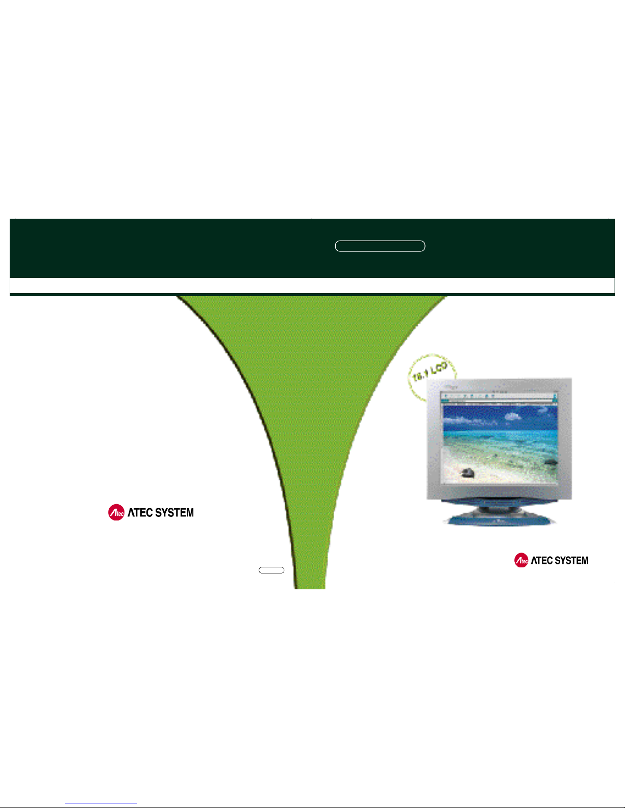
N E OVIEW AL181
18.1 TFT LCD MONITOR
LCD PC No.1 Company
#1451-78, Seocho-Dong, Seocho-Gu,Seoul,
137-867, Korea
TEL : 82-2-2190-5000 FAX : 82-2-2190-5009
h t tp:// w w w . a t e c h . c o . k r
USER MANUA L
[ FOR EXPORT ]
ANALOG / DIGITAL
Page 2
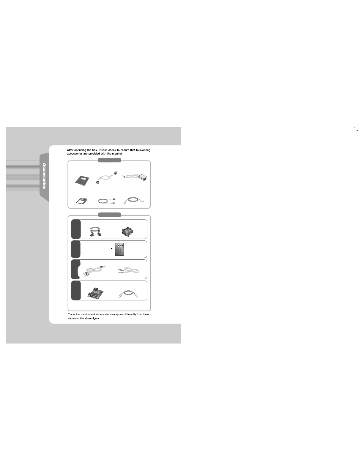
User Manual
Power Cord
VGA Signal Cable
DC Power Supply Unit
If you select DVI for your choice, we do not provide
VGA Signal Cable but only DVI Cable.
▼
Monitor Driver
▼
▼
Audio Cable
▼
▼
▼
▼ ▼
F o u n d a t i o n
O p t i o n
Audio Cable(RCA Type)
USB 4PORT
▼
D V I(Digital Video Interface)
▼
Cable VIDEO RCA
▼
Cable USB
▼
DVI to VGA ADAPTOR
D V I
REMOTE CONTROL
(Batteries Included)
V I D E O
T V
U S B
Page 3
FCC Compliance Statement
This device complies with Part 15 of the FCC Rules. Operation is subject to the
following two conditions : (1) this device may not cause harmful interference, and
(2) this device must accept any interference received including interference that
may cause undesired operation.
INFORMATION TO THE USER
This equipment has been tested and found to comply with the limits for a Class B
digital device pursuant to Part 15 of the FCC Rules. These limits are designed to
provide resonable protection against harmful interference in a residential
installation.
This equipment generates, uses and can radiate radio frequency energy and if not
installed and used in accordance with the instructions, may cause harmful
interference to radio communication. However, there is no guarantee that
interference will not occur in a particular installation. If turning the equipment off and
on, the user id encouraged to try to correct the interference by one more of the following measures :
- Reorient or relocate the receiving antenna.
- Increase the separation between the equipment an receiver.
- Connect the equipment into an outlet in a circuit different from that to which the
receiver is connected.
- Consult the dealer or an experienced radio / TV technician for help.
W A R N I N G
Changes or modifications not expressly approved by the manufacturer could void
the user's authority to operate the equipment.
Page 4

CE Conformity Notice
The Product herewith complies with the requirements of the Low Voltage
Directive 73/23/EEC and the EMC Directive 89/336/EEC and carries the "CE" mark
a c c o r d i n g l y .
Confirms to the following harmonized European standards have been applied:
EMC : EN 55022 Class B: 1998
EN 55024: 1998 (EN 61000-4-2: 1995, A1: 1998, EN 61000-4-3:1996,
EN 61000-4-4: 1995, EN 61000-4-5: 1995, EN 61000-4-6: 1996,
EN 61000-4-8: 1993 and EN 61000-4-11: 1994)
EN 61000-3-2: 1995, A1: 98, A2: 98
EN 61000-3-3: 1995
Page 5
2
6
10
12
14
1 8
1 7
25
2 8
1
B e fo re Use
H ow do I use the Monitor ?
I n fo rm ation for Your Conv e n i e n c e
F e a t u r e s
Installing Monitor Driver
Instructions for Safety
How do I Connect the Computer Cables ?
How do I Connect with the IBM computer ?
Parts and Functions of ANALOG and MONITOR
Front view
Back view
The name and function of each individual part
ANALOG OSD (On Screen Display) Display
Selection and Control
D I S P L AY ADJUST
MISC ADJUST
OSD ADJUST
E X I T
Parts and Functions of DIGITAL and MONITOR
DIGITAL OSD (On Screen Display) Display
Selection and Control
OSD Display
In case the connection is made by VGA Signal
In case the connection is made by S-VIDEO
In case the connection is made by COMPOSITE and S-VIDEO
In case the connection is made by TV (Tu n e r )
T r o u b l e s h o o t i n g
Product Specification
Please keep the user manual in a place where product users can refer to it.
Page 6

18.1 TFT LCD
Panel Adopted
•Adopted the 18.1 LCD (Liquid Crystal Display) Panel which allows you efficient
use in a small space due to the slim design.
D V I
•As for most of LCD Monitors released, we support only ANALOG input, but DVI in
accordance with the user's option as the video card for it has been widely used.
You can get clearer pictures in DIGITAL input than in ANALOG input.
A U D I O
•It gives user an amplified stereo sound through internally installed
s p e a k e r s ( 2 W ) .
D E S I G N
•It is outstanding that Atec system has strategically planned and laid out
a beautiful design that meets the taste of the new generation, super-slim model.
•Swivelling at 120 °to the right and the left, Tilting at 30°to the up and down.
Handle for Conveyance
•We do have made a handle for the easy transport carriage of monitor.
Power Consumption Economy Function
•The VESA DPMS (Display Power Management Signaling) function is
available to reduce power consumption by automatically switching the computer
into the power saving mode if the system doesn’t operate for a fixed period of time.
OPTION
•USB 4Port can be embedded to use the USB without an external Hub.
•RCA and S-VHS terminal is supplied, connecting this apparatus to DVD, VCR
or CAMCORDER.
•You may view TV programs after connecting with an antenna or a cable TV.
F e at u re s
Page 7

Installing Monitor Drive r
Manual installation method in Display Properties of Win 98 or Win 98SE
1. Insert a Diskette to A: Drive.
2. As clicking on My Computer in windows screen, follow the directions below.
① Click on‘Control Panel’
② Click on‘D i s p l a y’
③ Click on‘S e t t i n g s’
⑤ Click on‘M o n i t o r’,
then ‘C h a n g e’
⑥ Click on‘N e x t’
④ Click on‘A d v a n c e d’
Page 8
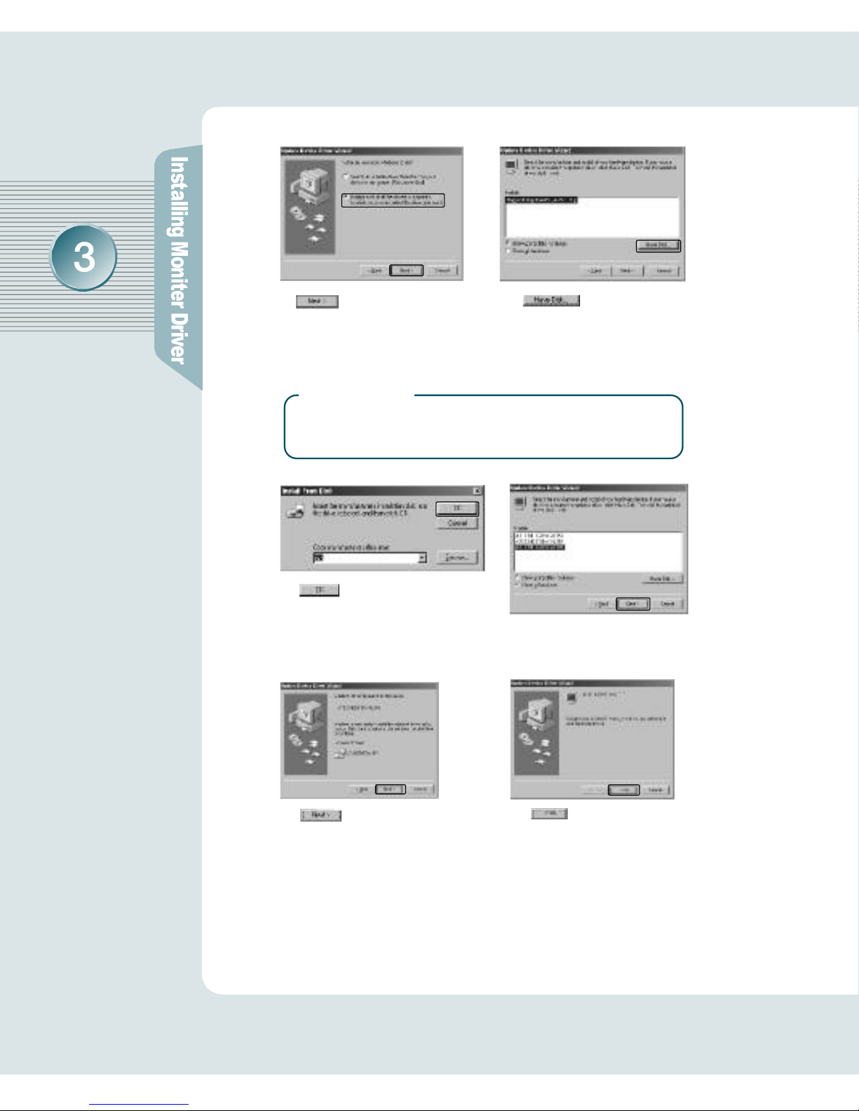
⑦ Click ‘Display a list
of all the drivers in a specific
location, so you can select
the driver you want ’
⑧ Click on
‘Have Disk ’
⑨ Click on‘O K’
⑩ Select ‘ATEC NEOVIEW
A L 1 8 1’, then click on‘N e x t’
⑪ Click on‘N e x t’
⑫ Click on‘F i n i s h’
3. If the model name of monitor has been changed, click
o n‘C l o s e’to restart Wi n d o w s .
▶
R e f e r e n c e
If it doesn't show up the relevant model in device selection
screen, click on "List all Device", then select one of them.
Click on "OK"
Page 9
Installing Monitor Drive r
Windows 2000 Monitor Driver Installation
The followings are the way to install monitor driver in
Windows 2000 Manual Installation in Display Properties.
❶ Press "Start", click "Settings" and "Control Panel".
❷ Click "Display" in "Control Panel".
❸ Click "Settings", then "Advanced".
❹ Select "Monitor", then "Properties".
❺ Choose "Driver", then "Update Driver...".
❻ Click "Next".
❼ Click "Display a list of all the drivers in a specific location, so you can select the
driver you want". Then Click on "Next".
❽ Click on "Have Disk".
❾Pointing to where the diskette or drive is located, then click on "OK".
E X 1 ] Insert a diskette to A drive bay, then press "Enter".
EX2] Pointing to where the driver is located: hard disk or network.
Then press "Enter".
EX3] If you can't correctly designate the driver route, then click "Search" to
find out the right one.
❿ Select the customer's model in "Model Selection" screen. Then press " Next".
Click on "Next".
Press "Yes".
If "Driver installation has been successfully completed" is popped up,
press "Finish".
Click "Close", then press "OK" to close the display screen.
Page 10
Installing Monitor Drive r
Configuring Monitor in Linux
It is the direction for installing monitor in Linux.
❶ You'd make xf86config file to run X-WINDOW. Your monitor is surely and
easily configured with this file. This file will be made as running xf86config.
❷ Press Enter in the first and second screen after running xf86config file.
❸ In third screen, we come up with the mouse setting screen.
❹ Configure it as opt for user system.
❺ Next will be the screen for selecting KeyBoard.
❻Configure it as opt for user system.
❼First, configure a horizontal frequency. Please refer to the horizontal frequency
in monitor manual. (User may directly input frequency.)
❽Next, configure a vertical frequency. Please refer to the vertical frequency in
monitor manual. (User may directly input frequency.)
❾Then, configure a monitor.
❿Type in the model name of monitor. The monitor's identification and description
(typed in here) aren't directly related with the execution of X-WINDOW.
After complete with other hardware settings, run X-WINDOW.
As the configuration has been successfully finished, save a configuration file.
Now run X-WINDOW. Theoretically, it is supposed to be executed.
But in some cases, it won't even start. In this case, edit a xf86config file.
Page 11
I n s t ructions for Safe t y
▶Matters that demand special attention are divided into
‘W a r n i n g’and ‘C a u t i o n’, and are detailed a follows
In case of the possibility that a serious injury or death
may occur during a violation of the instructions.
In case of the possibility that a slight injury or product
damage may occur during a violation of the instructions.
Wa rn i n g
C a u t i o n
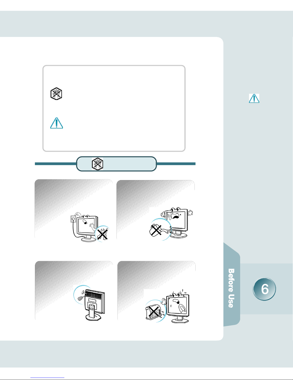
Wa rn i n g
No one but trained repair
engineers may disassemble the
monitor. Please contact the
appropriate sales agency or customer counsel window for
check-ups, adjustment and repair.
A fire or electric
shock accident
may be caused.
Please note not to allow liquids
such as chemicals, water etc to
contact the monitor.
A fire or electric shock
accident may
be caused.
D o n’t place or drop metals (such
as coins, hair pins, or ironware)
or flammable items (such as
paper, or matches) onto the
m o n i t o r .
A fire or electric
shock accident may
be caused.
D o n’t place the monitor near to
heat sources (such as a
fireplace), and keep out
of the sun.
A fire or electric shock
accident may
be caused.
※The sign on the product
and userguide instructs
as following.
※A sign signifies the
need for particular attention in order to avert
potential danger under
certain conditions.
Page 12

Wa rn i n g
Please insert the two pins of the
plug completely so that the
power supply unit can be
connected tightly.
Unsafe power
connections may
cause a fire.
Please be careful to keep the
panel from being scratched or
damaged when you transport
the monitor.
The panel may be
damaged,
causing a failure.
D o n’t set up the equipment in a
humid environment (such as
bathroom, rainy or windy area,
e t c ) .
Accidents of
electric shock,
fire or failure
may occur.
Please stop using in case of
smoke or abnormal odors.
Immediately switch off the power,
and pull out the power cord from
the wall. Contact the service center.
Continuity of use in
such a state may
cause a fire or
electric shock.
D o n’t sprinkle water directly on
any part of the monitor body.
An electric shock
or fire accident
may occur.
Please keep the power cord from
proximity to a heating instrument.
The covering material
of the cord may
melt, causing
a fire or electric
s h o c k .
Page 13
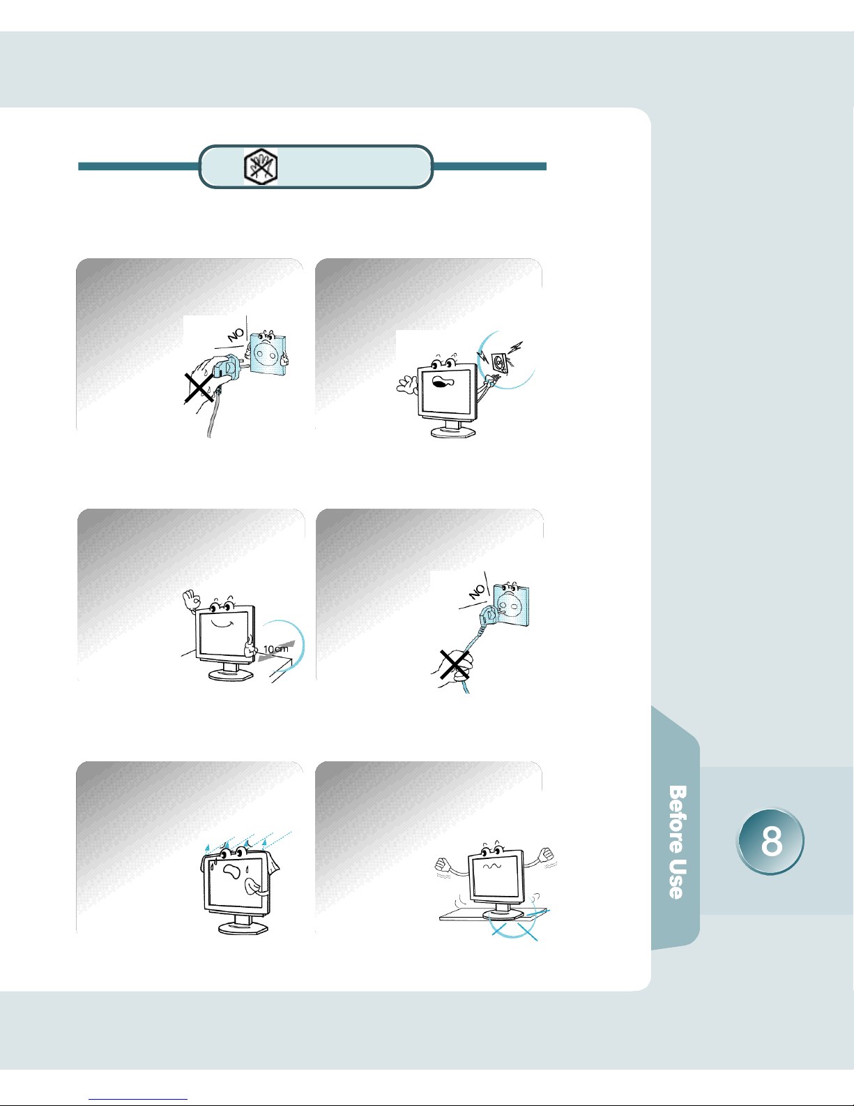
Wa rn i n g
Never touch the power plug with
wet hands.
An electric shock
accident may occur.
D o n’t use a power cord or plug
that is damaged or has a loose
connection.
An electric shock or ignition
may be caused.
Please note that air-flow holes
must not be blocked by a table
cloth or curtain.
A fire may becaused
due to an increase
in internal temper a t u r e .
D o n’t set up the equipment on an
unsupported shelf or angled
surface. nor on an area subject to
serious vibration.
Fall or displacement
of the equipment
may cause an injury.
Please set up the monitor at a
proper distance (over 10 cm)
away from the wall
for sufficient ventilation.
A fire may be
caused due to
an increase in
internal temper a t u r e .
Please grasp the power plug at the
base to remove it from the wall,
and pull firmly but gently.
If you yank at the cord
the wire may be broken,
causing ignition or
heat generation.
Page 14

C a u t i o n
Wa rn i n g
You must switch the power off and
pull the power cord out before
moving the monitor. You should
also check as to whether external
connection cords - such as the
connection cords between component parts - are all pulled out
before the
m o v e m e n t .
A damaged cord may
cause a fire or electric shock.
Pull the power cord out when the
monitor is not used for a long
time, or while you are away.
A dust covering may
cause an electric shock,
electric leakage,
or fire by heat
generation,
ignition, and
insulation degradation.
D o n’t set the monitor in a narrow
place with poor ventilation such
as a bookcase
A fire may be
caused due to
an increase in
internal temperature.
When you clean the panel
surface, pull the power cord out
first, and wipe the surface with a
clean, dry and soft cloth. Don ’t
use a damp cloth.
Such action may
be the main
cause of an
electric shock
accident and failure.
D o n’t put pressure upon the panel
or score the surface with your
hands or sharp items (nails, pencils,
pens, etc).
Damage or failure
of the panel may
be caused.
When you move the monitor, take hold
of it with both hands setting the panel
f o r w a r d .
If you drop the monitor,
contact the service
center to check it for
a susceptibility to fire
or electric shock.
Page 15
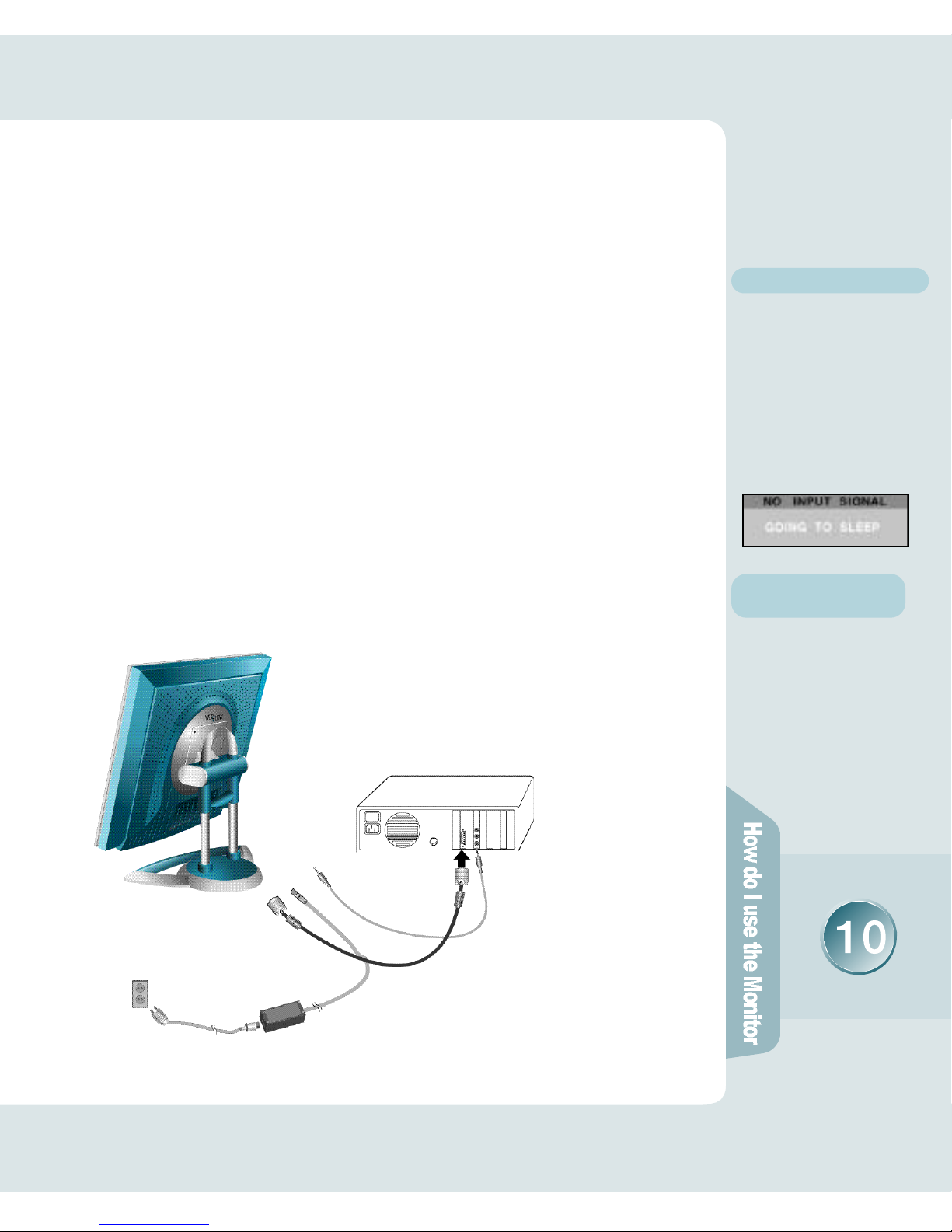
H ow do I connect the computer cabl e s ?
How do I connect with the IBM computer ?
◈ In case of the monitor aiding ANALOG (VGA)
Ensure that the computer, monitor and peripheral equipment power is
turned off.
Connect signal cable to D-Sub signal input connector, and VGA signal
cable to signal input connector of monitor.
Connect one DC power jack of DC power supply unit to the 12V
terminal, and the other to the power cord. Next connect the power
cord to the concent.
Turn the monitor power on after switching the computer power on.
If the message“NO INPUT SIGNAL ”shows up, check the connection
of VGA signal cable or connector.
Switch the monitor and computer power off at the end of use.
Audio Cable
▶AUDIO Cable is connected
to LINE OUT
VGA Signal Cable
DC Power Supply Unit
Power Cord
1 .
2 .
3 .
4 .
5 .
6 .
▶ R e f e r e n c e
No Input signal message
It is a message appeared in
case signal input cable is
inexactly connected between
monitor and computer.
Please refer to the message
“Please confirm before you
report the trouble”for details.
Connect with the
Macintosh computer
Use the appropriate MAC to
VGA adapter block at your
s y s t e m .
Page 16

H ow do I connect the computer cabl e s ?
How do I connect with the IBM computer ?
◈ In case of the monitor aiding DIGITAL (DVI)
Ensure that the computer, monitor and peripheral equipment power is
turned off.
Connect Signal Cable.
① In case of using DIGITAL Cable.
- Connect one DVI Signal Cable each to the mainframe and monitor.
② In case of using ANALOG Cable (Refer to the left side illustration).
- Connect DVI to VGA adaptor positioned at the rear side of the monitor.
Then connect it to the mainframe.
Connect one DC power jack of DC power supply unit to the 12V
terminal, and the other to the power cord. Next connect the power
cord to the concent.
Turn the monitor power on after switching the computer power on.
If "NO INPUT SIGNAL" appears, check the DVI Cable (or VGA Signal
Cable connection).
Switch the monitor and computer power off at the end of use.
Audio Cable
▶AUDIO Cable is connected
to LINE OUT
DVI Signal Cable
DC Power Supply Unit
Power Cord
In case of using ANALOG in
DVI model monitor, you
must set up the adaptor as
shown on the illustration.
▶ R e f e r e n c e
1 .
2 .
3 .
4 .
5 .
6 .
Page 17

Front View
Pa rts and Functions of AN A LO G
and MONITO R
Power Pilot Lamp
Back View
1 2 3 4 5 6 7 8 9
1. DC 12V INPUT (connected to adaptor)
2. VGA(Analog) or DVI(Digital) INPUT [DVI is OPTION]
3. S-VHS INPUT (video image input 2)
4. RCA INPUT (video image input 1)
5. AUDIO IN (connected to LINE OUT of PC's mainframe)
6. AUDIO OUT (linked to external speaker or headset)
7. USB UP (connected to PC's mainframe)
8. USB 4DOWN(connected to USB KeyBoard, Mouse, and Camera)
9. TV ANTENNA (connected to antenna cable for televiewers)
* 2 DVI , 3 , 4, 7, 8, 9 are OPTION.
MENU Button
SELECT Button
DOWN Button
UP Button
AUTO Button
POWER Button
❷
Page 18

The Name and Function of Each Individual Part in the Screen Adjusting Block
Parts and Functions of ANALOG and
M O N I TO R
Front Monitor
It makes OSD menu picture appear or disappear.
It is also used when you enter into or get out of submenu.
❶ MENU Button
Used to select an icon to be adjusted from the OSD screen.
❷ SELECT Button
The screen is automatically adjusted to the optimal display state applicable to the
current mode, while the following message appears.
❺ A U TO Button
It is for shifting OSD screen to up and down or increase and decrease the value
of icon selected. (And it also volume up and down without pressing MENU.)
❸ DOWN Button ❹ UP Button
❶ ❷ ❸ ❹ ❺ ❻
Once pressed, it powers up the system. Once more, it shuts down the system.
- Green ON : system activated
- Amber Blinking : 1. System Standby
2. Monitor Power Saving Mode
3. VGA signal cable Unhooked
❻ POWER Button
Lights up during the operation but goes out if you turn
the power off.
Power Pilot Lamp
Page 19

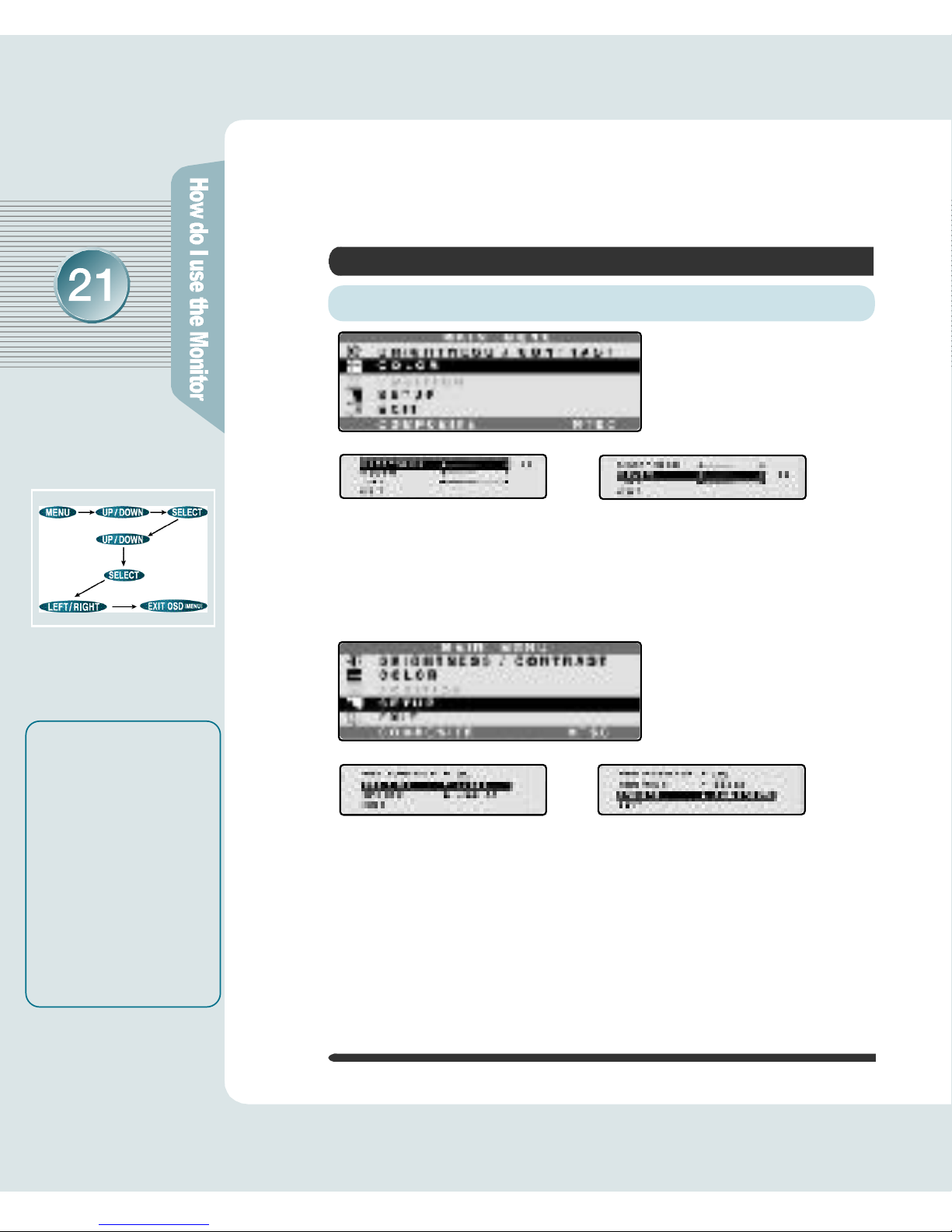
ANALOG OSD (On Screen Display) Display
Selection and Control
Use the OSD adjustable buttons on the side of the monitor to set/adjust to
the best screen and operating environment.
❶ Press MENU Button to show you OSD menu screen.
❷ Press DOWN Button to select the preferred main
menu, then
press MENU Button once more to get in subordinate
menu screen.
❸ As pressing UP / DOWN Button, you can go to the menu
that you
p r e f e r. Press SELECT Button.
❹ Set the preferred value as using UP / DOWN Button.
❺ Press MENU Button once more, then it reverts to the
main menu
screen.
❻ As using DOWN Button , go back to EXIT OSD.
If you have to adjust the screen,
please adhere to the following procedure.
AUTO Function
If you select the AUTO
button before using the
OSD menu, the screen is
automatically adjusted to
the optimal display state
applicable to the current
mode, while the following
message appears.
If you don’t like the auto
adjustment, you have to
manually adjust the H/V
Position, Clock, and Phase
of the OSD menus.
AUTO is most appropriate
when it is operated on
background display color
closest to white.
(For more information,
p le a se r e f e r to p a g e s
15 - 21)
Page 20

ANALOG OSD (On Screen Display) Display
Selection and Control
•
B R I G H T N E S S
- It is used to adjust brightness of the screen.
•
C O N T R A S T
- It is used to adjust distinction.
•
P H A S E - It is used to adjust the phase of
the screen. Please use it in case there is
noises or lines are overlapped.
•
DOS MODE - It is to optimize TEXT and
GRAPHIC.
•
R GAIN - Modify the value of red.
•
G GAIN - Modify the value of green.
•
B GAIN - Modify the value of blue.
MISC ADJUST
DISPLAY ADJUST
Descriptions of OSD Adjustment and Functions
•
CLOCK - Controlling the horizontal size in screen.
•
H- POSITION - It is used to move screen right-wards or left-wards.
•
V- POSITION - It is used to move screen up-wards or down-wards.
•
COLOR TEMPERATURE - configured to one of 9500, 8000,
6500(Default), and 5000.
- 9500 : selected to blue color hued screen.
- 5000 : selected to red color hued screen.
•
WHITE BALANCE- It automatically sets Color Balance.
(It will be adjusted to optimization after making background screen a white color.)
•
FACTORY DEFAULT (Manufactured Initial Value)
- It goes back to the initial value that has been
set as forwarding.
•
AUTO (Auto Set) - It is configured as the most
appropriate, optimized screen.
Page 21

ANALOG OSD (On Screen Display) Display
Selection and Control
EXIT
•
EXIT OSD
- It goes out of OSD menu.
Descriptions of OSD Adjustment and Functions
OSD ADJUST
•
H-POS (OSD horizontal position)
- Horizontal position in OSD menu is
adjusted as controlling the numerical
value of it.
•
V-POS (OSD vertical position)
- Vertical position in OSD menu is adjusted
as controlling the numerical value of it.
•
OFF TIME (Setting OSD disappearance time) - OSD menu configures a
disappearance time. The maximum time of 100 sec may be set, so that it
will automatically vanish unless any input value is noticed within 100 sec.
(Default:15 Sec)
•
TRANSPARENCY (OSD Transparency) - It configures the basic color of
OSD menu from opacity to transparency.
•
L A N G U A G E - One of English, Japanese, Korean, German, French and
Spanish may be selected.
▶ R e f e r e n c e
Ver 1.0
1280X1024 / 60Hz
Page 22

D I G I TAL OSD (On Screen Display) Display
Selection and Control
Front Monitor
It makes OSD menu picture appear or disappear.
It is also used when you enter into or get out of submenu.
❶
MENU Button
Use SELECT button if you wish to change OSD value.
SOURCE will change when you press SELECT button. (If you press once, the present
SOURCE will appear. Press once more, the SOURCE will convert.)
❷
SELECT Button
When you press this button, it is automatically adjusted to the most appropriate condition
to present mode. This does not function when DIGITAL VIDEO CARD (DVI Card) is
used. (It is adjusted automatically.)
❼
A U TO Button
Use these buttons when moving up and down in OSD (It is TV channel increase
(UP) and decrease (DOWN) function when this button is pressed without pressing
MENU button.)
❸
DOWN Button ❹UP Button
It is used to increase and decrease the SELECTION ICON value in OSD display. (It
is the VOLUME increase and decrease function when this button is pressed without
pressing MENU button.)
❺
LEFT Button❻RIGHT Button
❶ ❷ ❸ ❹ ❺ ❻ ❼ ❽
Once pressed, it powers up the system. Once more, it shuts down the system.
- Green ON : system activated - Amber ON : 1. System Standby
2. Monitor Power Saving Mode
3. VGA signal cable Unhooked
❽
POWER Button
Lights up during the operation but goes out if you turn
the power off.
Power Pilot Lamp
The Name and Function of Each Individual Part in the Screen Adjusting Block
Page 23

D I G I TAL OSD (On Screen Display) Display
Selection and Control
▶Function Description
▶Mode Information
▶ A message indicating PROCESSING
S t a t u s !
•'PROCESSING AUTO CONFIGURATION' is a message demanding your patience while monitor is
searching for the most appropriate background disp l a y .
•'POWER SAVER MODE' is a message indicating
the monitor is on the process of entering the Power
Saver Mode.
•'OUT OF FREQUENCE' is a message indicating an
input signal is out of boundary, which monitor can
handle. This is case which video card output has
problems of either not aiding "plug-and-play" or not
clearly recognizing the monitor's information, so
please check with the Aid Resolution (Page 26).
▶ A message during AUTO
CONFIGURATION operation.
▶ A message while Power Saver Mode
is on the process (converts into
Power Saver Mode after 5 seconds).
▶ A message indicating failure of
entered signal
PROCESSING Message
OSD Display
Descriptions of OSD Adjustment and Functions
❶ When you press the
MENU button
without OSD display, the display
shown above will appear.
❷ You can indicate and enter in by UP/DOWN buttons.
❸ At this point, you can enter in when you press the menu you have
selected and can be controlled by UP/DOWN buttons.
At this point, converted contents can be checked by graphs and numbers
Indicated numbers, in domain value, can be controlled and they are not the
absolute value.
▶ R e f e r e n c e
◈ No need to press AUTO
CONFIGURATION button
when Digital Video Card
is used (it is controlled
a u t o m a t i c a l l y ) .
◈Vertical Frequency can be
aided up to 60Hz when
SXGA 1280X1024 is used
in Digital Monitors
(does not aid to 75Hz).
Page 24

D I G I TAL OSD (On Screen Display) Display
Selection and Control
▶ Control the Screen Brightness
▶ Control the Screen's Shade of
C o l o r
In case the connection is made by VGA Signal
Descriptions of OSD Adjustment and Functions
▶ P R E S E T 1 : Light Blue Display
P R E S E T 2 : General Display
▶ RED, GREEN, BLUE:
Color Chosen by User
▶ H O R I Z O N T A L : Display Horizontal
M o v e m e n t
V E R T I C A L : Display Vertical
M o v e m e n t
C L O C K : Control of the Display
Quality by Increasing
Display's Size
P H A S E : Detailed Control of the
Display Quality.
◈ No need to press AUTO
CONFIGURATION button
when Digital Video Card
is used (it is controlled
a u t o m a t i c a l l y ) .
◈Vertical Frequency can be
aided up to 60Hz when
SXGA 1280X1024 is used
in Digital Monitors
(does not aid to 75Hz).
▶ R e f e r e n c e
Page 25

▶ OSD POSITION : Rotates in this order: top left side, top right side, middle,
bottom right side, bottom left side.
OSD TIME : Waiting period for OSD indication when no control is made
during OSD screen display.
S O U R C E : Converts any input signal into ANALOG,DIGITAL,COMPOSITE,
S-VIDEO and TUNER.
D I G I TAL OSD (On Screen Display) Display
Selection and Control
In case the connection is made by VGA Signal
Descriptions of OSD Adjustment and Functions
In case the connection is made by COMPOSITE and S-VIDEO
▶ Control Darkness Level of Signal
▶ Control the Screen's Shade
of Color
◈ No need to press AUTO
CONFIGURATION button
when Digital Video Card
is used (it is controlled
a u t o m a t i c a l l y ) .
◈Vertical Frequency can be
aided up to 60Hz when
SXGA 1280X1024 is used
in Digital Monitors
(does not aid to 75Hz).
▶ R e f e r e n c e
Page 26
▶ S H A R P N E S S : Control Screen Distinction
C O L O R : Control Screen's Depth of Color
T I N T : Control Screen's Tint of Color
▶OSD POSITION : Rotates in this order : top left side, top right side, middle,
bottom right side, bottom left side.
OSD TIME: Waiting period for OSD indication when no control is made during
OSD screen display.
S O U R C E : Converts any input signal into ANALOG, DIGITAL, COMPOSITE,
S-VIDEO and TUNER.
D I G I TAL OSD (On Screen Display) Display
Selection and Control
In case the connection is made by COMPOSITE and S-VIDEO
Descriptions of OSD Adjustment and Functions
▶ R e f e r e n c e
◈ No need to press AUTO
CONFIGURATION button
when Digital Video Card
is used (it is controlled
a u t o m a t i c a l l y ) .
◈Vertical Frequency can be
aided up to 60Hz when
SXGA 1280X1024 is used
in Digital Monitors
(does not aid to 75Hz).
Page 27

◈ No need to press AUTO
CONFIGURATION button
when Digital Video Card
is used (it is controlled
a u t o m a t i c a l l y ) .
◈Vertical Frequency can be
aided up to 60Hz when
SXGA 1280X1024 is used
in Digital Monitors
(does not aid to 75Hz).
▶ R e f e r e n c e
D I G I TAL OSD (On Screen Display) Display
Selection and Control
▶ Control the Screen Brightness
▶ Control the Screen's Shade of
C o l o r
In Case when a Connection is made with TV (Tuner) Signal
Descriptions of OSD Adjustment and Functions
▶ P R E S E T 1 : Light Blue Display
P R E S E T 2 : General Display
▶ RED, GREEN, BLUE
:Color Chosen by User
Page 28

▶ AIR / CATV : Air Wave, Cable TV Selection ▶ AUTO CHANNEL
: Automatically Selects Clear Channels
▶ MANUAL CHANNEL
: Selects to Insert or Delete on Each Channel
▶ F I N E : Any Noise Occurred on Display is
Handled by a Microscopic Control
D I G I TAL OSD (On Screen Display) Display
Selection and Control
In Case when a Connection is made with TV (Tuner) Signal
Descriptions of OSD Adjustment and Functions
▶OSD POSITION : Rotates in this order : top left side, top right side, middle,
bottom right side, bottom left side.
OSD TIME: Waiting period for OSD indication when no control is made dur-
ing OSD screen display.
SOURCE : Converts any input signal into ANALOG, DIGITAL, COMPOSITE,
S-VIDEO and T U N E R.
◈ No need to press AUTO
CONFIGURATION button
when Digital Video Card
is used (it is controlled
a u t o m a t i c a l l y ) .
◈Vertical Frequency can be
aided up to 60Hz when
SXGA 1280X1024 is used
in Digital Monitors
(does not aid to 75Hz).
▶ R e f e r e n c e
◈When you have to move MONITOR, use AUTO CHANNEL to select clear channels.
Page 29
D I G I TAL OSD (On Screen Display) Display
Selection and Control
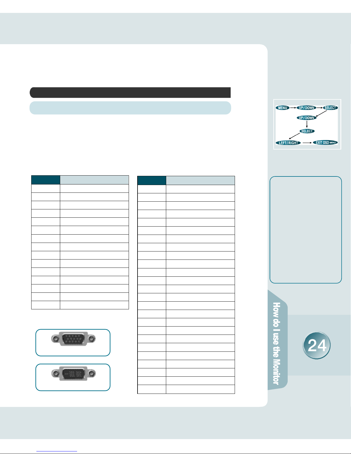
Pin Arrangement Description
I N F O R M ATION (Comparison between ANALOG and ADAPTO R )
- Input Signal : ANALOG Formula
- Connector : 15 Pin VGA Signal
C a b l e
- 15 Pin D-Sub Connector
- The Purchased Monitor's Signal
Cable is positioned on the rear
side of Stand
- Input Signal : Digital Formula
- Connector : DVI-D model Cable
- DVI-D Connector
•15 Pin D-Sub Connector Pin
D e s c r i p t i o n
Signal Description
TMDS DATA2TMDS DATA2+
TMDS DATA2+/Shield
N C
N C
DDC SCL
DDC SDA
N C
TMDS DATA1TMDS DATA1+
TMDS DATA1/Shield
N C
N C
+5V Power
G N D ( f o r + 5 V )
Hot Plug Detection
TMDS DATA0TMDS DATA0+
TMDS DATA0/Shield
N C
N C
TMDS Clock/Shield
TMDS Clock
TMDS Clock
G N D
•DVI-D Connector Pin Description
Pin Number
1
2
3
4
5
6
7
8
9
1 0
1 1
1 2
1 3
1 4
1 5
1 6
1 7
1 8
1 9
2 0
2 1
2 2
2 3
2 4
S h e l l
Signal Description
R e d
G r e e n
B l u e
G N D
S e l f - C h e c k
Red GND
Green
G N D
Blue
G N D
E x i t
G N D
G N D
Data Line (SDA)
Horizontal Synchronizer
Vertical Synchronizer
Data Click (SCL)
Pin Number
1
2
3
4
5
6
7
8
9
1 0
1 1
1 2
1 3
1 4
1 5
D - S u b
D V I - D
◈ No need to press AUTO
CONFIGURATION button
when Digital Video Card
is used (it is controlled
a u t o m a t i c a l l y ) .
◈Vertical Frequency can be
aided up to 60Hz when
SXGA 1280X1024 is used
in Digital Monitors
(does not aid to 75Hz).
▶ R e f e r e n c e
Page 30
Tr o u b l e s h o o t i n g
Please check the below particulars before you contact the service
center to notify an abnormality of the monitor.
Take these respective actionsCheck these points
Is the monitor power cord
inserted ?
Is the power turned off ?
Is the power turned on and
the power pilot lamp Blinking
Amber?
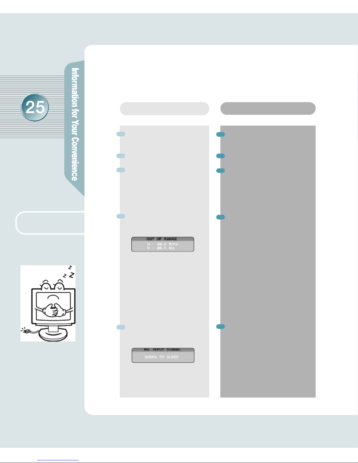
Is the message “Out Of
R a n g e”shown ?
Is the message “No Input
S i g n a l”s h o w n ?
Please connect the power cord
correctly to the concent.
Please press the power button.
The monitor is in the power saving mode. Please therefore
move the mouse, press any key
on the keyboard, or recheck
VGA Cable connection.
If a power indicating lamp of
amber color blinks, press any
key to go back to previous
mode. As it passes over the fre-
quency limit of horizon (31.5-80
kHz) and verticality (60-75 Hz)
in PC (video card), you'd reconfigure it as referring to the speci-
fication of this manual. (If you
install the monitor driver that we
have provided, it won't come up
with the message “OUT OF
R A N G E”. )
It shows up as PC changes to
power-saving mode or the
signal cable between PC and
monitor isn't rightly connected.
Move your mouse or press key-
board button. But it won't still
show you a right screen, then
recheck a signal cable
c o n n e c t i o n .
This symptom
can be discovered
The screen doesn’t
show anything.
Page 31
Tr o u b l e s h o o t i n g
Please check the below particulars before you contact the service center
to notify an abnormality of the monitor.
Take these actionsCheck these points
Has a discoloration (into 16
colors) of the screen occurred?
Do you see a spot on the
s c r e e n ?
Set the number of colors to more
than 256 colors. On the Windows
95/98, perform the following
process
[Control Panel] -> [Display] ->
[Setting] -> [Color Table] -> [256
Colors] -> [OK]
You may see a few spots (in red,
green, white and black) on the
screen during the operation.
Occurrence of such a phenomenon is not a failure but a characteristic of the LCD panel, and
therefore has no relation to the
performance of the monitor.
This symptom
can be discovered
The color of the screen
is not normal
Page 32

Tr o u b l e s h o o t i n g
Please check the below particulars before you contact the service center
to notify an abnormality of the monitor.
Is the positional adjustment
made correctly?
Is the phase adjustment made
p r o p e r l y ?
Is the screen set in the best
state?
Push the 'AUTO' Button, then the
screen will beadjusted automatically in to the optimal state applicable to the current mode.
If you are not satisfied with the
auto adjustment, you can directly
adjust the H Position (Horizontal
Position), V Position (Vertical
Position), and Clock (Horizontal
Size) of the OSD menus.
Push the 'AUTO' Button, then the
screen will beadjusted automatically in to the optimal state applicable to the current mode.
If you are not satisfied with the
auto adjustment, you maym a n u a lly adjust the Phase (Focus) of the
OSD menus.
While you are using this product
in the mode of 1280X1024 and
60Hz, the best condition of the
screen is available. In the
mode of VGA(640x480),SVGA
(800x600) or XGA (1024x768),
the outline of a letter may be seen
dimly or unevenly.
Take these actionsCheck these points
The screen is under a bias
toward one side, or is not
centrally positioned.
A faint letter is shown, or
the phase is out of focus.
Noise is also generated
horizontally.
This symptom
can be discovered
Page 33

LCD Panel
P i c t u r e
S i g n a l
A U D I O
I n p u t
C o n n e c t o r
Dimension
and We i g h t
P o w e r
Product Specification
The details of product specification can be changed without notice to
improve the product.
2
panel type
screen size
pixel size
contrast
color
brightness
resolution
horizontal frequency
vertical frequency
view angle
input picture signal
output
input terminal
u s e r’s control
body size(WxDxH)
weight
power managing system
power consumption
input power
a-Si active matrix TFT-LCD
18.1 (459.14mm) diagonal
0.2805mm x 0.2805mm
2 5 0 : 1 ( T y p i c a l )
8-bit(16,777,216 Colors)
200cd/m
SXGA 1280 x 1024@ 60Hz
31.5 - 80kHz
60 - 75Hz
U / D :±7 0°, R/L: ±7 0°
Analog RGB,OPTION
(DVI, RCA, S-VHS)
Stereo 2Watt x 2
15Pin D-Sub
(Analog RGB)
, OPTION
( D V I )
Auto Configuration, Brightness,
Contrast, H-Position, V-Position,
Color RGB, Phase, Frequency,
Volume, Language,etc.
448x 241.3x 441mm
7.5kg(Unit), 10kg(Packed)
VESA DPMS standard
≤48 Watt
AC 110~220V, DC12V
Page 34

Product Specification
Factory-specified Mode
Horizontal
F r e q u e n c y ( k H z )
Vertical
F r e q u e n c y ( H z )
1
2
3
4
5
6
7
8
9
1 0
11
1 2
1 3
640 ×3 5 0
640 ×4 8 0
640 ×4 8 0
640 ×4 8 0
720 ×4 0 0
800 ×6 0 0
800 ×6 0 0
800 ×6 0 0
1 0 2 4×7 6 8
1 0 2 4×7 6 8
1 0 2 4×7 6 8
1280 ×1 0 2 4
1280 ×1 0 2 4
3 1 . 4 7
3 1 . 4 7
3 7 . 8 6
3 7 . 5 0
3 1 . 4 7
3 7 . 8 8
4 8 . 6 8
4 6 . 8 8
4 8 . 3 6
5 6 . 4 8
6 0 . 0 2
6 4 . 0
7 9 . 9 8
7 0
6 0
7 2
7 5
7 0
6 0
7 2
7 5
6 0
7 0
7 5
6 0
7 5
V G A
V G A
V G A
V G A
V G A
S V G A
S V G A
S V G A
X G A
X G A
X G A
S X G A
S X G A
Factory-specified Mode
※ R e m a r k s
1. The indication in above diagram and actual value shall not be always coincident.
This product automatically adjusts for optimum condition by itself.
2. In case of any trouble in user's set-up, it automatically returns to the initial
set-up mode.
 Loading...