

Page 1
Rev 1.0
LCD PC No.1 Company
#1451-78, Seocho-Dong, Seocho-Gu,Seoul,
137-867, Korea
TEL : 82-2-2190-5000 FAX : 82-2-2190-5009
h t tp://w w w . a t e c h . c o . k r
[
FOR EXPORT
]
N E OVIEW AL150
USER MANUA L
1 5 . 0" TFT LCD MONITOR
Page 2
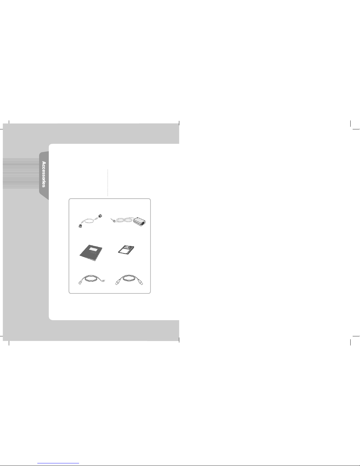
After openning the box, Please check to ensure that followering
accessories are provided with the monitor
The actual monitor and accessories may appear differently from those
shown on the above figure
User Manual
Power Cord
VGA Signal Cable
(Option) USB Cable
DC Power Supply Unit
Monitor Driver
Page 3
8
4
3
9
1 1
15
1 8
B e fo re Use
A ge n cy Reg u l ation Notice
H ow do I use the Monitor ?
I n fo rm ation for Your Conv e n i e n c e
F e a t u r e s
Instructions for Safety
How do I Connect the Computer Cables ?
How do I Connect with the IBM computer ?
The Name and Function of Each Individual Part
Front view
Back view
The name and function of each individual part in the screen adjusting block
How to Select and Adjust the OSD (On Screen Display)
MENU ADJUST
OSD ADJUST
EXIT
T r o u b l e s h o o t i n g
Product Specification
Please keep the user manual in a place where product users can refer to it.
FCC / CE
1
Page 4
CE Conformity Notice
The Product herewith complies with the requirements of the Low Voltage
Directive 73/23/EEC and the EMC Directive 89/336/EEC and carries the "CE" mark
a c c o r d i n g l y .
Confirms to the following harmonized European standards have been applied:
EMC : EN 55022 Class B: 1998
EN 55024: 1998 (EN 61000-4-2: 1995, A1: 1998, EN 61000-4-3:1996,
EN 61000-4-4: 1995, EN 61000-4-5: 1995, EN 61000-4-6: 1996,
EN 61000-4-8: 1993 and EN 61000-4-11: 1994)
EN 61000-3-2: 1995, A1: 98, A2: 98
EN 61000-3-3: 1995
FCC Compliance Statement
This device complies with Part 15 of the FCC Rules. Operation is subject to the
following two conditions : (1) this device may not cause harmful interference, and
(2) this device must accept any interference received including interference that
may cause undesired operation.
INFORMATION TO THE USER
This equipment has been tested and found to comply with the limits for a Class B
digital device pursuant to Part 15 of the FCC Rules. These limits are designed to
provide resonable protection against harmful interference in a residential
installation.
This equipment generates, uses and can radiate radio frequency energy and if not
installed and used in accordance with the instructions, may cause harmful
interference to radio communication. However, there is no guarantee that
interference will not occur in a particular installation. If turning the equipment off and
on, the user id encouraged to try to correct the interference by one more of the following measures :
- Reorient or relocate the receiving antenna.
- Increase the separation between the equipment an receiver.
- Connect the equipment into an outlet in a circuit different from that to which the
receiver is connected.
- Consult the dealer or an experienced radio / TV technician for help.
W A R N I N G
Changes or modifications not expressly approved by the manufacturer could void
the user's authority to operate the equipment.
Page 5

* The sign on the product
and userguide instructs
as following.
* A sign signifies the
need for particular attention in order to avert
potential danger under
certain conditions.
1 5 . 0" (38.016cm) LCD Panel Adopted
- Adopted the 15.0" LCD (Liquid Crystal Display) Panel which allows you efficient
use in a small space due to the slim design.
A Dynamic Convenient Design
-. The Embodyment of Wall-mounted Display.
Plug & Play Function
- The Plug & Play function is available, freeing the user from having to reboot
or set up the system during operation.
- The user does not have to adjust the monitor to computer connection, as
optimal screen settings are automatically provided through the DDC (Display
Data Channel) system.
Power Consumption Economy Function
- The VESA DPMS (Display Power Management Signaling) function is
available to reduce power consumption by automatically switching the computer
into the power saving mode if the system doesn't operate for a fixed period of
t i m e .
AUDIO Function
- A speaker is embedded so that the user can hear sound without separate
s p e a k e r s .
O P T I O N
- USB 4Port can be embedded to use the USB without an external Hub.
No one but trained repair
engineers may disassemble the
monitor. Please contact the
appropriate sales agency or customer counsel window for
check-ups, adjustment and repair.
A fire or electric
shock accident
may be caused.
Please note not to allow liquids
such as chemicals, water etc to
contact the monitor.
A fire or electric shock
accident may
be caused.
- Matters that demand special attention are divided into
'W a r n i n g' and 'C a u t i o n' and are detailed a follows
In case of the possibility that a serious injury or death
may occur during a violation of the instructions.
In case of the possibility that a slight injury or product
damage may occur during a violation of the instructions.
Wa rn i n g
C a u t i o n
D o n't place or drop metals (such
as coins, hair pins, or ironware)
or flammable items (such as
paper, or matches) onto the
m o n i t o r .
A fire or electric
shock accident may
be caused.
D o n't place the monitor near to
heat sources (such as a
fireplace), and keep out
of the sun.
A fire or electric shock
accident may
be caused.
Wa rn i n g
Page 6

Please insert the two pins of the
plug completely so that the
power supply unit can be
connected tightly.
Unsafe power
connections may
cause a fire.
Please be careful to keep the
panel from being scratched or
damaged when you transport
the monitor.
The panel may be
damaged,
causing a failure.
D o n't set up the equipment in a
humid environment (such as
bathroom, rainy or windy area,
e t c ) .
Accidents of
electric shock,
fire or failure
may occur.
Please stop using in case of
smoke or abnormal odors.
Immediately switch off the power,
and pull out the power cord from
the wall. Contact the service center.
Continuity of use in
such a state may
cause a fire or
electric shock.
D o n't sprinkle water directly on
any part of the monitor body.
An electric shock
or fire accident
may occur.
Please keep the power cord from
proximity to a heating instrument.
The covering material
of the cord may
melt, causing
a fire or electric
s h o c k .
Never touch the power plug with
wet hands.
An electric shock
accident may occur.
Don't use a power cord or plug
that is damaged or has a loose
connection.
An electric shock or ignition
may be caused.
Please note that air-flow holes
must not be blocked by a table
cloth or curtain.
A fire may becaused
due to an increase
in internal temper a t u r e .
D o n' t set up the equipment on an
unsupported shelf or angled
surface. nor on an area subject to
serious vibration.
Fall or displacement
of the equipment
may cause an injury.
Please set up the monitor at a
proper distance (over 10 cm)
away from the wall
for sufficient ventilation.
A fire may be
caused due to
an increase in
internal temper a t u r e .
Please grasp the power plug at the
base to remove it from the wall,
and pull firmly but gently.
If you yank at the cord
the wire may be broken,
causing ignition or
heat generation.
Wa rn i n g
Wa rn i n g
Page 7
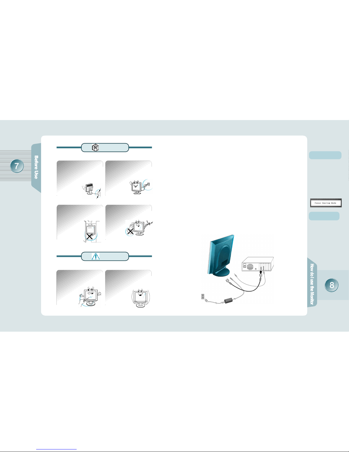
'Power Saving Mode'
m e s s a g e
If the signal input cable
between the monitor and
computer isn't correctly
connected, this message
will be displayed on the
screen. For more inform
-ation, please refer to
'T
r o u b l e s h o o t i n g'
Connect with the
Macintosh compute r
Use the appropriate MAC
to VGA adapter block at
your system.
D o n't put pressure upon the panel
or score the surface with your
hands or sharp items (nails, pencils,
pens, etc).
Damage or failure
of the panel may
be caused.
When you move the monitor, take
hold of it with both hands setting the
panel forward.
If you drop the monitor,
contact the service
center to check it for
a susceptibility to fire
or electric shock.
How do I connect with the IBM computer ?
How do I connect the computer cables?
Ensure that the computer, monitor and peripheral equipment
power is turned off.
Connect signal cables with the D-Sub signal input connector and
the monitor signal input connector respectively.
Connect one DC power jack of DC power supply unit to the 12V
terminal, and the other to the power cord. Next connect the power
cord to the concent.
Turn the monitor power on after switching the computer power on.
If the message ‘Power Saving Mode’ shows up, check the
connection of the VGA signal cable or connector.
Switch the monitor and computer power off at the end of use.
Power Cord
DC Power Supply Unit
1 .
2 .
3 .
4 .
5 .
6 .
You must switch the power off and
pull the power cord out before
moving the monitor. You should
also check as to whether external
connection cords - such as the
connection cords between component parts - are all pulled out
before the
m o v e m e n t .
A damaged cord may
cause a fire or electric shock.
Pull the power cord out when the
monitor is not used for a long
time, or while you are away.
A dust covering may
cause an electric shock,
electric leakage,
or fire by heat
generation,
ignition, and
insulation degradation.
D o n't set the monitor in a narrow
place with poor ventilation such
as a bookcase
A fire may be
caused due to
an increase in
internal temperature.
When you clean the panel
surface, pull the power cord out
first, and wipe the surface with a
clean, dry and soft cloth. Don't
use a damp cloth.
Such action may
be the main
cause of an
electric shock
accident and failure.
Wa rn i n g
C a u t i o n
Audio Cable
- AUDIO Cable is connected
to LINE OUT
VGA Signal Cable
Page 8

AUTO Function
If you select the SELECT
button before using the
OSD menu, the screen is
automatically adjusted to
the optimal display state
applicable to the current
mode, while the following
message appears.
If you don' t like the auto
adjustment, you have to
manually adjust the H/V
Position, Clock, and Phase
of the OSD menus. (For
more information, please
refer to pages 11 - 14)
Front View
The Name and Function of Each
Individual Part
The Name and Function of Each Individual Part in the Screen Adjusting Block
The Name and Function of Each
Individual Part
Back View
Power Pilot Lamp
(1) (2) (3) (4) (5) (6)
M E N UButton
S E L E C TB u t t o n
D O W NButton UP Button
AUTO Button
POWER Button
Front Monitor
It makes OSD menu picture appear or disappear.
It is also used when you enter into or get out of submenu.
(1) MENU Button
Used to select an icon to be adjusted from the OSD screen.
(2) SELECT Button
The screen is automatically adjusted to the optimal display state applicable to the
current mode, while the following message appears.
(5) A U TO Button
It is for shifting OSD screen to up and down or increase and decrease the value
of icon selected. (And it also volume up and down without pressing MENU.)
(3) DOWN Button (4) UP Button
(1) (2) (3) (4) (5) (6)
Once pressed, it powers up the system. Once more, it shuts down the system.
- Green ON : system activated
- Amber ON : 1. System Standby
2. Monitor Power Saving Mode
3. VGA signal cable Unhooked
(6) POWER Button
Lights up during the operation but goes out if you turn
the power off.
Power Pilot Lamp
(1):
DC 12V INPUT (connected to adaptor)
(2): VGA(Analog) INPUT
(3):
AUDIO IN (connected to LINE OUT of PC's mainframe)
(4):
AUDIO OUT (linked to external speaker or headset)
(5):
USB UP (connected to PC's mainframe)
(6):
USB 4DOWN
(connected to USB KeyBoard, Mouse and Camera)
*
(5), (6) are OPTION.
Stand Control Button
Stand Control Button comes
to Tilt up to -5 ~ 20 and is
fixed at 20.
In case of folding the stand,
you should control with the
button pressed as in the
p i c t u r e .
*Refer to the
left side
Page 9

How to Select and Adjust the OSD
(On Screen Display) Screen
Use the OSD adjustable buttons on the side of the monitor to set/adjust to
the best screen and operating environment.
(1)If you click MENU button, OSD menu display appears.
(2)Click UP/DOWN button, move to MENU you want, and
choose by clicking SELECT button.
(3)Set the preferred value as using UP / DOWN Button.
(4)
Click SELECT buttonand store your adjusted state.
(5)If you click SELECT buttononce more, OSD display
d i s a p p e a r s .
If you have to adjust the screen,
please adhere to the following procedure.
How to Select and Adjust the OSD
(On Screen Display)
MENU ADJUST
Descriptions of OSD adjustment and functions
-. CLOCK - Controlling the horizontal size in
s c r e e n .
-. P H A S E- It is used to adjust the phase of
the screen. Please use it in case there is
noises or lines are overlapped.
-. B R I G H T N E S S
- It is used to adjust brightness of the screen.
-. C O N T R A S T
- It is used to adjust distinction.
-. H- POSITION- It is used to move screen
right-wards or left-wards.
-. V- POSITION- It is used to move screen
up-wards or down-wards.
-. AUTO C O N F I G U R A T I O N
- It is configured as the most
appropriate, optimized screen.
Page 10

How to Select and Adjust the OSD
(On Screen Display)
How to Select and Adjust the OSD
(On Screen Display)
Descriptions of OSD Adjustment and Functions
-.P r e s e t - embody the best color.
(the initial value of factory)
-. Preset - choose the blue screen color.
-.User Color : color defined by use.
-. Red Gain - change the value of red color.
-. Green Gain - change the value of green
c o l o r .
-. Blue Gain - change the value of blue color.
-. E x i t - escape from in color.
MENU ADJUST
OSD ADJUST
-. H-POS (OSD horizontal position)
- Horizontal position in OSD menu is
adjusted as controlling the numerical
value of it.
-. V-POS (OSD vertical position)
- Vertical position in OSD menu is adjusted
as controlling the numerical value of it.
-.
L A N G U A G E - One of English, Italiano,
Deutsch, French and Spanish may be
s e l e c t e d .
Descriptions of OSD Adjustment and Functions
EXIT
-. EXIT MENU
-. It goes out of OSD menu.
OSD ADJUST
-. OFF TIMER
-. OSD menu configures a disappearance time.
The maximum time of 60 sec may be set, so
that it will automatically vanish unless any input
value is noticed within 16 sec. (Default:16 Sec)
-. EXIT
-. It goes out of OSD menu.
-.R e f e r e n c e
Ver 1.0
- OSD Version
1 0 2 4 x 768 / 48.4KHz x 6 0 . 0 H z
- resolution, screen scanning rate
-. FACTORY RESET
(the initial value of factory)
-. set to the initial value in case of factory
f o r w a r d i n g
Page 11

Take these actionsCheck these points
This symptom can
be discovered
Has a discoloration (into 16 colors) of the screen occurred?
Is the screen color unstable or
does it seem to be a single
c o l o r ?
Do you see a spot on the
s c r e e n ?
Is there the amplication function
to soundcard in computer?
Set the number of colors to more
than 256 colors. On the Windows
95/98, perform the following
process
[Control Panel] -> [Display] ->
[Setting] -> [Color Table] -> [256
Colors] -> [OK]
Check the connection of the
signal cable, and correct it if
anyabnormality is found.
You may see a few spots (in red,
green, white, and black) on the
screen during the operation.
Occurrence of such a phenomenon is not a failure but a characteristic of the LCD panel, and
therefore has no relation to the
performance of the monitor.
As the amplification is built in the
monitor of our product, you should
connect to LINE OUT of the
soundcard for use.
The color of the screen
is not normal
This symptom can
be discovered
The screen does't
show anything.
T r o u b l e s h o o t i n g
Please check the below particulars before you contact the service center
to notify an abnormality of the monitor.
Take these respective actionsCheck these points
Is the monitor power cord inserted ?
Is the power turned off ?
Is the power turned on with the
power pilot lamp lit Amber?
Is the message "Out Of Range"
shown ?
Is the message "Power Saving
M ode" shown?
Please connect the power cord
correctly to the concent.
Please press the power button.
The monitor is in the power saving
mode. Please therefore move the
mouse or press any key on the
keyboard.
The frequency of PC (Video Card)
is out of range (i.e., horizontal:
31-60kHz, vertical: 56-75Hz).
Please therefore see [Product
Specification] in this guide to
reset it in conformity with monitor
s p e c i f i c a t i o n s .
The signal cable isn't connected
between PC and monitor, or is
missing. Please check and
connect it properly.
T r o u b l e s h o o t i n g
Please check the below particulars before you contact the service center
to notify an abnormality of the monitor.
Page 12

The screen is under a bias
toward one side, or is not
centrally positioned.
A faint letter is shown, or the
phase is out of focus. Noise
is also generated
horizontally.
This symptom
can be discovered
T r o u b l e s h o o t i n g
Please check the below particulars before you contact the service center
to notify an abnormality of the monitor.
Is the positional adjustment
made correctly?
Is the phase adjustment made
p r o p e r l y ?
Is the screen set in the best
state?
Push the 'AUTO' Button, then the
screen will beadjusted automatically in to the optimal state applicable to the current mode.
If you are not satisfied with the
auto adjustment, you can directly
adjust the H Position (Horizontal
Position), V Position (Vertical
Position), and Clock (Horizontal
Size) of the OSD menus.
Push the 'AUTO' Button, then the
screen will be adjusted automatically in to the optimal state applicable to the current mode.
If you are not satisfied with the
auto adjustment, you may m a n u a lly adjust the Phase (Focus) of the
OSD menus.
While you are using this product
in the mode of 1024X768 and
60Hz, the best condition of the
screen is available. In the mode
of VGA(640x480) or
SVGA(800x600), the outline of a
letter may be seen dimly or
u n e v e n l y .
Take these actionsCheck these points
LCD Panel
P i c t u r e
S i g n a l
A U D I O
I n p u t
C o n n e c t o r
Dimension
and We i g h t
P o w e r
O p t i o n s
Product Specification
The details of product specification can be changed without notice to
improve the product.
2
panel type
screen size
pixel size
contrast
color
resolution
brightness
horizontal frequency
vertical frequency
view angle R/L:+/- 60, U/D:+/-45
input picture signal
output
input terminal
u s e r's control
body size(WxDxH)
Tilt Function
weight
power managing system
power consumption
input power
USB 4Port
a-Si active matrix TFT-LCD
15.0 "(38.016cm) diagonal
0.297mm x 0.297mm
3 0 0 : 1 ( T y p i c a l )
6-bit(262,144 Colors)
XGA 1024x7 6 8
200cd/m (Typical)
31.5 - 60kHz
56 - 75Hz
Analog RGB
Stereo 1W x 2
15Pin D-Sub
Auto Configuration, Brightness,
Contrast, H-Position, V-Position,
Color RGB, Clock Adjustment, Volume,
Phase Adjustment, Language,etc.
3 6 7 . 4x1 4 8 . 2x3 6 0 . 7 m m
- 5 ~ 20, 90
(In case of Wall Function Use)
3.5kg(Unit), 5.5kg(Packed)
VESA DPMS standard
<30 Watt
AC 100-240V, DC12V
Page 13

¸ð
´Ï
ÅÍ
¸¦
ȍ
¿ë
ÇÏ
·Á
¸é
Product Specification
Factory-specified Mode Horizontal
F r e q u e n c y ( k H z )
Vertical
F r e q u e n c y ( H z )
1
2
3
4
5
6
7
8
9
1 0
1 1
1 2
1 3
1 4
640 x 350
640 x 480
640 x 480
640 x 480
640 x 480
720 x 400
800 x 600
800 x 600
800 x 600
800 x 600
832 x 624
1024 x 768
1024 x 768
1024 x 768
3 1 . 4 7
3 5 . 0 0
3 1 . 4 7
3 7 . 8 6
3 7 . 5 0
3 1 . 4 7
3 5 . 1 6
3 7 . 8 8
4 8 . 6 8
4 6 . 8 8
4 9 . 7 3
4 8 . 3 6
5 6 . 4 8
6 0 . 0 2
7 0
6 7
6 0
7 2
7 5
7 0
5 6
6 0
7 2
7 5
7 5
6 0
7 0
7 5
V G A
M A C
V E S A
V E S A
V E S A
V G A
V E S A
V E S A
V E S A
V E S A
M A C
V E S A
V E S A
V E S A
Factory-specified Mode
 Loading...