

Page 1
Keytek Series 2000
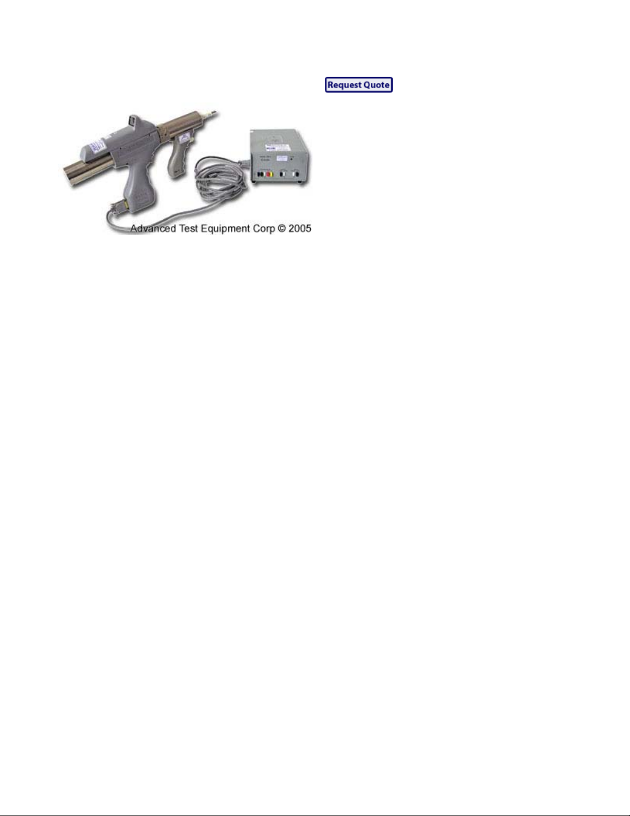
Keytek Series 2000 ESD Simulation System
GENERATORS
z
0 to 25 kV bipolar
z
Plug-in, interchangeable discharge networks for
different human body models
z
Separate simulations for all six key simulation
modes at discharge and its five components
Actual air discharge, plus:
* Current injection of standard waves
* Discharge magnetic field
* Discharge electric field collapse
* Pre-discharge electric field
* Pre-discharge corona-generated RF interference
z
Programmable repetitive operation
z
Interchangeable tips, ball, wedge, point , fi eld
generators
MONITORS
Digital voltage monitor measures and displays
1. Programmed high voltage before high
voltage trigger is depressed
2. Actual, measured high voltage during
charge and after discharge
3. Audible beeper to indicate discharge
Specifications
GENERAL
Voltage Range:
z
z
z
Polarity
Operating Modes
Repetition Rates
seconds.
Built-In Digital Voltmeter:
1 to 25 kV with Ball Tip (and without Extender
Cable EC-1)
1 to 20 kV with Point and Wedge Tips (DT-2, DT-
3)
1 to 20kV with Extender Cable EC-1 and any tip
: Operator-Selectable (plus or minus).
: Single-shot and repetitive.
: One shot per approximately 1, 3 or 10
Page 2

z
High Voltage Trigger On: Measures and displays
actual high voltage at the ESD Simulator's tip
z
High Voltage Trigger Off:
Before tip voltage has decayed to below 300-500V,
continues to measure and display tip high voltage
After tip voltage has decayed to below 300-500V,
displays "Program Voltage" -- the voltage that will
appear at the tip when the high-voltage trigger is
depressed
Program Voltage Adjust
potentiometer, mounted in thumb-accessible position on
ESD gun handle.
Discharge Ground Strap
IEC-specified return, but with insulation adequate fo r
25kV. Length ~ 2000mm, or 6.5ft.
Normal / Slow Ramp Selector
z
Slow Ramp Position: In Slow Ramp mode, for
repetition rates of one shot per 3 seconds and one
shot per 10 seconds, the high-voltage ramps up
slowly enough to permit the digital voltmeter to
display the voltage at which the simulated ESD
breakdown occurs
z
Normal Ramp Position: Preferred for most other
work.
z
Normal ( Single-Shot ) / Burst Selector: In Burst
position, allows realistic simulation of multiple
discharges even when the ESD tester is on a tripod
or is otherwise in a fixed location
DISCHARGE NETWORKS
: Multi-turn, long-life
: Inductance equivalent to that of
DN-1
z
Energy Storage Capacitor: 150pf
z
Discharge Resistor: 150ohm
Optional Discharge Networks
DN-2
DN-3
DN-4
DN-5
DN-6
Energy Storage
Capacitor (pF)
100 1500
700
150
700
150
20
60 10K
100 500
Discharge Resistor
(ohm)
100k
150
100K
150
30
Page 3

DN-10
150 330
 Loading...