

Page 1
For Communications Systems Worldwide (GSM, CDMA, IS-136A, PDC, PHS, DECT)
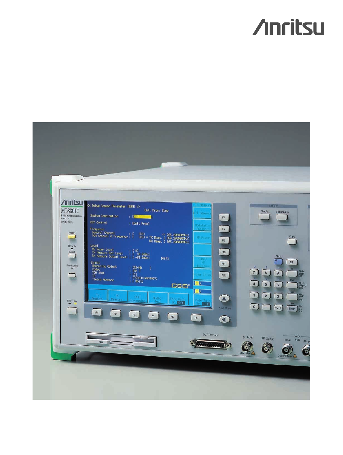
MT8801C
Radio Communication Analyzer
300 kHz to 3 GHz
Keyboard sold separately
Page 2
Page 3
For Worldwide Communications Systems
Every major radio communication system in the world,
including GSM/DCS1800/PCS1900, CDMA, IS-136A, PDC,
PHS and DECT, can be evaluated using just one MT8801C
Radio Communication Analyzer, covering the 300 kHz to
3 GHz frequency band in one hardware platform, and the
dedicated measurement software options. The call processing test and sensitivity test using loopback method are possible for GSM/DCS1800/PCS1900, CDMA, IS-136A and DECT.
In addition, connection testing, as well as send testing while
communicating, are also possible for PDC and PHS measurement by using the call processing function, and the PDC
uplink RCH can be monitored (RSSI, estimated error rate) too.
FM radio transmission/reception tests are simplified by using
the optional analog measurement function, and the optional
spectrum analyzer function covering 10 MHz to 3 GHz is very
useful for maintaining as well as measuring spurious near carrier on production lines. GPIB and RS-232C interfaces are
standard, so MT8801C can be incorporated easily into automated production lines or on-site automated testing systems.
1
All in
1 unit for GSM, CDMA,
IS-136A, PDC, PHS,
and DECT systems
All basic transmission and
reception measurements
performed by
1 unit
Unique High-Speed Measurement Method
The time required for testing equipment on production lines is
greatly reduced using the high-speed adjacent channel power
and occupied bandwidth measurement functions based on
Anritsu’s proprietary measurement algorithm and DSP (Digital
Signal Processing). Furthermore, major transmission test items
such as transmission frequency, modulation accuracy (phase
error), transmission power, rise/fall characteristics of burst
wave, adjacent channel power, etc., can be measured and
judged pass/fail for limit value of the each item.
System
Measurement
Description
type
software/option
IS-136A MX880113A
Tx and Rx measurements of IS-136A mobile stations
including call processing (Requires Option 01)
AMPS
Tx and Rx measurements: AMPS analog mobile stations
PCS1900
MX880114A and PCS1900 digital mobile stations, including call pro-
cessing (Requires Option 01)
GSM
Tx and Rx measurements of GSM system mobile stations
DCS1800
MX880115A
including call processing
PCS1900
DECT MX880118A
Tx and Rx measurements of PP/FP including call processing (Requires Option 07)
MX880116A
Tx and Rx measurements of PDC mobile stations including
PDC
call processing
MX880131A
Tx and Rx measurements of PDC mobile stations
MX880117A
Tx and Rx measurements of PHS mobile stations including
PHS
call processing
MX880132A
Tx and Rx measurements of PHS base stations and mobile
stations
GSM Option 11
Audio test of GSM mobile stations including call
processing (requires MX880115A and Option 01)
CDMA Option 12
Tx and Rx measurements of mobile stations including
call processing (Requires Option 01)
Page 4
4
Rapid Measurement
Batch Measurements of Transmission Test Items
Example for PDC/PHS, only about 1 second is
required to measure all major transmission test items,
including frequency, modulation accuracy, origin offset, transmission rate, transmission power, leakage
power during carrier-off, rise/fall edge characteristics,
occupied bandwidth, and adjacent channel power.
Pass/fail decisions for limit value of each test item can
also be displayed.
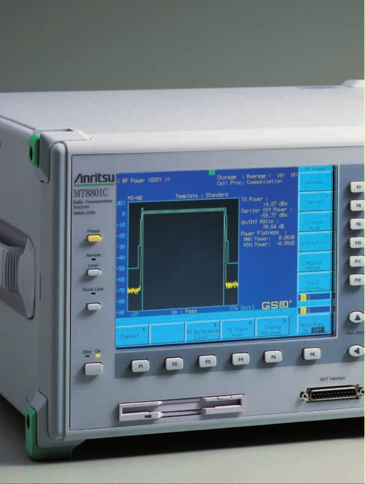
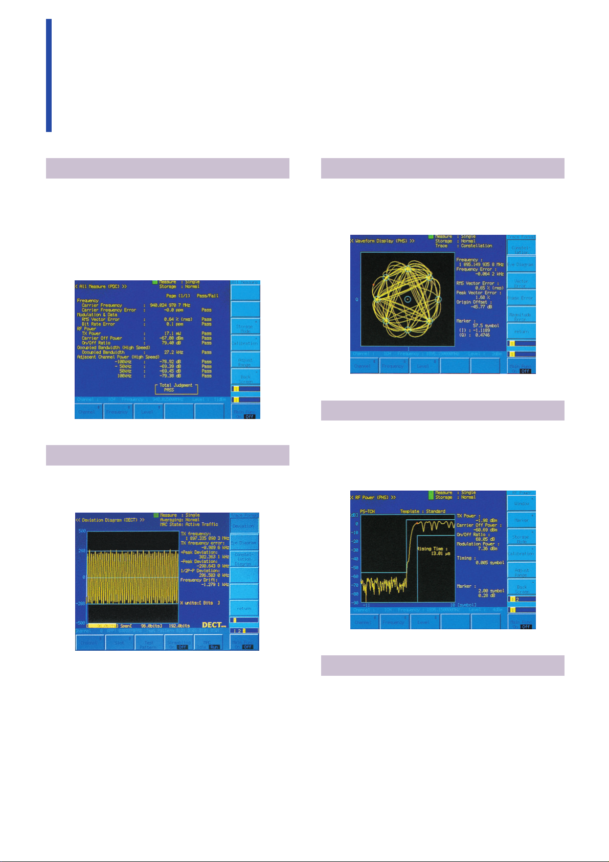
Measurement of Antenna Power
Rise/Fall Edge Characteristics
Antenna power rise/fall edge characteristics can be
measured simultaneously with antenna power measurements. In addition, the marker points can be
moved and the power can be read directly with 1/10
symbol resolution.
Calibration Functions
A built-in thermocouple power sensor is used for calibration, providing accurate measurement of absolute
values such as average power with burst signal and
leakage power during carrier-off. There is no need for
other instruments; Just one press of the CAL key during measurement performs calibration.
Modulation Analysis
The user can display the waveform as either frequency
deviation, eye diagram or constellation diagram to
easily show any irregularities in the modulation.
Constellation Display Functions
The I/Q vector components of measured signals are
displayed. The frequency error, RMS/PEAK vector
errors, and origin offset can be shown on the same
screen.
Example of burst rise characteristics (PHS)
Example of constellation display (PHS)
Example of linked send measurement items (PDC)
Example of transmitter modulation (DECT)
Page 5
5
Wide-Band Power Meter
The power meter with built-in thermocouple power
sensor can accurately measure power between 0 and
+40 dBm.
Receiver Sensitivity Measurement
This function displays the error count and error rate in
the RF input or DATA/CLOCK input measured signal.
Adjacent Channel Power Measurement
The MT8801C can measure adjacent channel power
for each communication system at high speed.
Call Processing Function
The MT8801C acts as a pseudo base station permitting to judge pass/fail for registration, origination,
termination, communication, handover (PHS: TCH
switching type only), disconnection from network and
disconnection from mobile station at the sequence
monitor screen.
Bit error rate measurement (IS-136A)
Adaptive BER Receiver Testing
For DECT measurements, there are one FER and two
BER measurements. The two measurements, one
quick and the other full, allow the number of samples
required to conclude a test to be adapted to suit the
receiver being tested.
Output RF spectrum measurement (GSM)
Example of power measurement
Sequence monitor display (GSM)
Example of bit error rate measurement (DECT)
Page 6
6
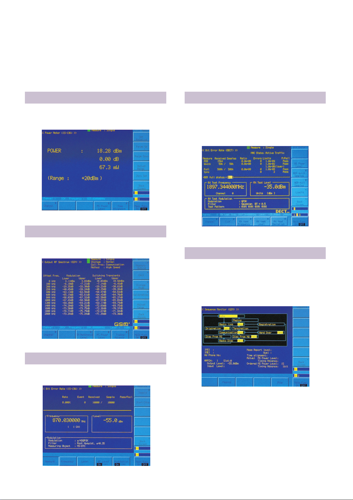
Transmission Measurement
Characteristics such as frequency, power, and frequency deviation can be measured easily.
AF Low Impedance Output (Option 04)
This option converts the output impedance of the AF
oscillator of the Option 01 Analog Measurement to
low impedance. It permits direct driving of an external
speaker connected to the AF output connector.
Reception Measurement
An FM modulated signal is output to permit measurement of the frequency and level of the AF signal from
a receiver, as well as SINAD and distortion.
AF Measurement
An AF signal is output to measure the frequency, level
and distortion of the AF signal at the DUT.
Analog Measurement
Analog Measurement Function (Option 01)
The MT8801C has general analog measurement functions too. Efficient FM TX/RX testing is made easy by
built-in signal generator, AF oscillator, RF analyzer
(power meter, frequency counter, FM measurement)
and audio analyzer functions. This function is especially useful for the IS-136A analog test.
Transmission Measurement with SG Function
Transmission characteristics can be measured by outputting an FM RF signal from the built-in signal generator.
Page 7
7
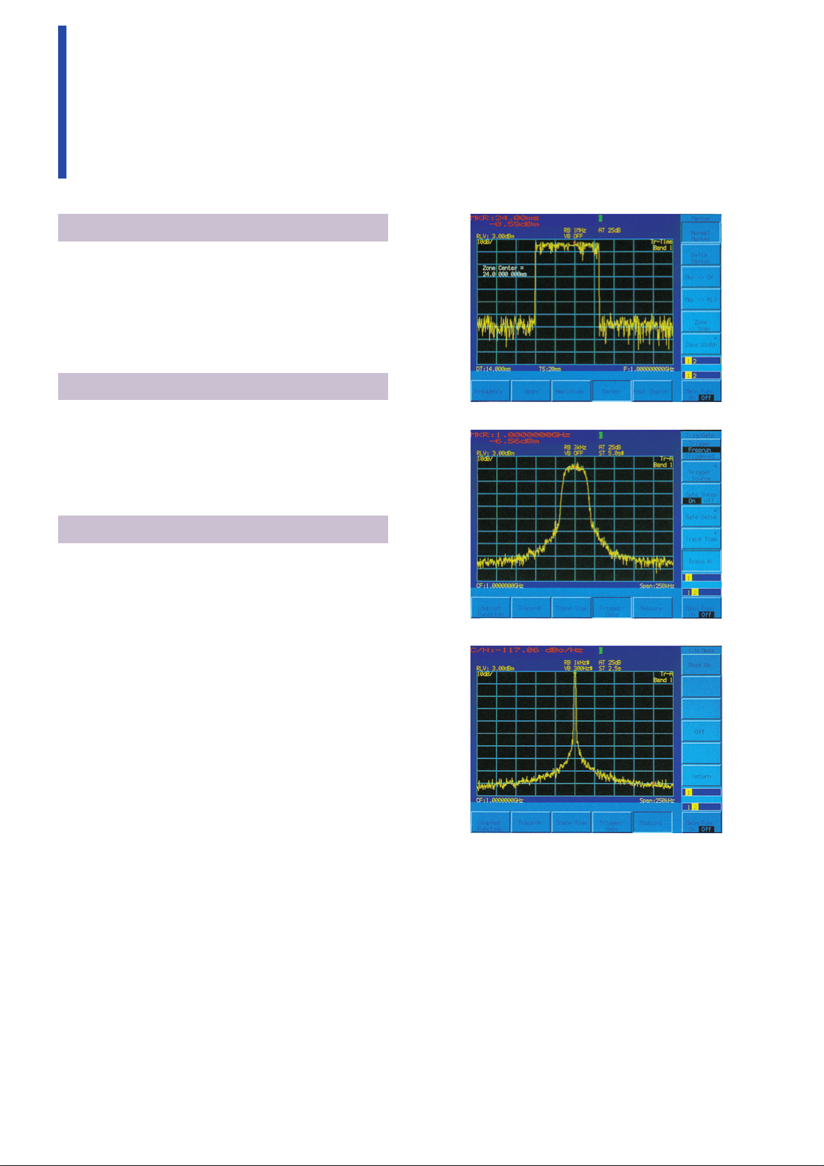
Spectrum Analyzer Function (Option 07)
The spectrum analyzer with synthesized local covers
a frequency range of 10 MHz to 3 GHz with a resolution of 1 Hz. In addition to a C/N of –115 dBc (100 kHz
offset), the RBW can be set to 300 Hz to 1 MHz, the
VBW to 3 to 100 kHz, and the sweep time in the frequency domain to 100 ms to 1000 s (1 ms to 1000 s in
time domain).
High-Accuracy Measurement
The total level accuracy is an astonishing ±1.5 dB due
to the analyzer’s excellent linearity, and the level calibration function. Moreover, the average noise level is
just –85 dB max. (at 10 MHz to 1 GHz), and the secondary harmonic distortion is –60 dB max. (100 MHz
to 1.5 GHz).
Convenient Functions
The analyzer has a full lineup of useful functions
including marker, delta marker, and gate sweep functions. It also has advanced displays such as average,
max. hold, cumulative and overwrite. Trace A and
Trace B can be measured on a dual screen in the frequency domain, along with noise power, C/N, occupied bandwidth, adjacent channel power, and average
power of burst signal.
Burst wave measurement in time domain
IS-136A modulated wave measurement
Spectrum Analysis
C/N measurement
Page 8

8
GSM Audio Test (Option 11)
When using with the MX880115A GSM Measurement
Software, speech Tx/Rx characteristics can be measured in accordance with GSM Rec. RPE LTP (Full
Rate Speech CODEC).
The audio signal generated by the MT8801C is digitally processed and ideal audio signal is sent. In addition, this option can also be used to digitally process
an audio signal sent from a GSM terminal for high-reliability and high-accuracy measurement.
Tx Audio Test
The MT8801C can decode an audio signal sent from a
GSM terminal to measure the speech coding characteristics of the DUT.
Rx Audio Test
In this test, the audio signal from the MT8801C is
decoded by the DUT and the speech signal decoding
characteristics are measured.
Audio Echo Test
In this test, the audio signal from the DUT is looped
back by the MT8801C and the characteristics of coding through encoding is measured.
Page 9

9
CDMA Measurement
CDMA Measurement (Option 12)
The Option 12 can measure the following systems;
USA 800-MHz cellular band (TIA/EIA/IS-95A standard), USA 1.9 GHz PCS band (ANSI J-STD-008 standard), Japan 800-MHz cellular band (ARIB STD-T53
standard).
The CDMA and analog dual mode standardized in the
IS-95A standard are supported.
CDMA Measurement Items
CDMA transmission measurement
Access probe output power
Stand-by power
Burst power
Burst power vs. time
Burst off power
Carrier on/off ratio
Carrier frequency, frequency error
Waveform quality, timing error
Modulation accuracy (vector error, phase error, amplitude error, origin offset)
Open-loop power control time response
Occupied bandwidth
Spurious close to the carrier
Spurious
CDMA reception measurement
CDMA signal generator
Frame error ratio
AWGN generator
Analog transmission/reception measurement
Audio oscillator
Noise generator
Modulation analysis (modulation factor, distortion)
Frequency counter
FM signal generator
Call processing function
Registration
Call origination
Call termination
Conversation
Loopback
Frequency channel switching (IS-95A standard: dual
mode)
Disconnection from mobile station and network
Waveform quality measurement
Gated output power measurement
Frame error rate measurement
Page 10

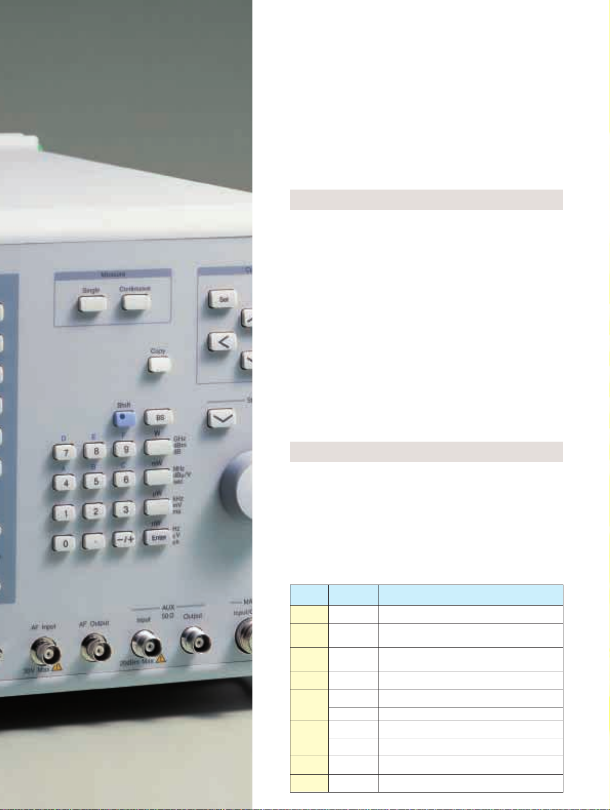
Intuitive Key Layout, Simple Operation
10
1
Keys corresponding to on-screen function keys.
The number of displayed function keys can be
increased using the Page key.
2
Keys for inputting measurement parameters.
3
Keys for selecting single or continuous measurement.
4
Keys for moving cursor and opening/closing the
parameter setting window.
5
Floppy disk drive for saving and recalling measuring conditions. It is also used to upgrade measurement software by loading the upgrade software.
(Measurement software resides in internal memory;
the floppy disk drive is used when upgrading this
software.)
6
Connector for input of data and clock for error rate
measurements. (BNC connectors on the rear panel
are also for data and clock input.)
7
Audio analyzer and AF Oscillator I/O Connector are
used to evaluate FM radio equipment and AF circuits.
8
Auxiliary I/O connector for obtaining signal generator output at higher levels than provided by MAIN
connector, or for analyzing low-level signals (No
function is provided for calibration of absolute
power measurements.)
9
Connector for antenna output of radio equipment
for reception/transmission tests. It can also serve
as input to the power meter.
5
Page 11

6
11
1
98
432
7
Page 12

12
GPIB Interface (standard)
All key operations except the power switch can be
controlled remotely.
RS-232C Interface (standard)
All key operations except the power switch can be
controlled remotely. The RS-232C interface can be
used with notebook computers not having a GPIB
port to configure a measurement system.
Parallel Interface (standard)
The parallel Centronics interface to print the MT8801C
screen to a printer.
Connection with DUT (2): PDC, PHS
For Configuration of Automated Measurement Systems
Spectrum Analyzer
MS2602A Printer
GPIB
MT8801C Personal computer
Printer
RS-232C, GPIB
MT8801C Personal computer
Centronics
MT8801C Printer
MT8801C
Data TTL level
DUT Clock
Level
TTL level
converter
✽
Controller*
Personal computer, etc.
✽
✽Provided by user
Saving Screen
MT8801C screens can be saved to FD as bitmapped
files (exclusive use with printer connected to parallel
interface).
Example of bitmapped file
Connection with DUT (1): GSM, DECT
This setup also be used for IS-136A, CDMA, PDC and
PHS transmitter test.
MT8801C DUT
Connection with DUT (3): IS-136A
MT8801C DUT Controller*
Personal computer, etc.
✽
✽Provided by user
Page 13

13
Specifications
Frequency range 300 kHz to 3 GHz
Maximum input level +40 dBm (10 W, MAIN connector), +20 dBm (100 mW, AUX connector)
MAIN I/O connector
Input/output connector
Impedance: 50 Ω, N-type
VSWR:
#1.2 (#2.2 GHz), #1.3 (.2.2 GHz)
AUX input/output connector: TNC-type
Frequency: 10 MHz
Starting characteristics:
#5 ✕ 10
-
8
/day (after 10 minutes of warm-up, referred to frequency after 24 hours warm-up)
Reference oscillator
Aging rate: #2 ✕ 10
-
8
/day, #1 ✕ 10–7/year (referred to frequency after 24 hours warm-up)
Temperature characteristics: #5 ✕ 10–8(0° to 50°C, referred to frequency at 25°C)
External standard input: 10 MHz or 13 MHz (±1 ppm), input level: 2 to 5 Vp-p
Frequency range: 300 kHz to 3 GHz
Power meter
Level range: 0 to +40 dBm, –10 to +40 dBm (CDMA measurement)
Level accuracy: ±10% (0 to +40 dBm, after zero-point calibration),
±10% (–10 to +40 dBm, 18° to 28°C, at average value, after zero-point calibration)
Frequency
Range: 300 kHz to 3 GHz
Resolution: 1 Hz
Accuracy: Reference frequency accuracy ±100 mHz
Output level
Level range (no modulation or analog modulation): –13 to –133 dBm (Main), +7 to –133 dBm (AUX)
Level accuracy: ±1 dB (10 MHz to 2.2 GHz, $–123 dBm, 18° to 28°C), ±3 dB (10 MHz to 2.2 GHz, $–133 dBm),
±2 dB (.2.2 GHz, $–123 dBm, 18° to 28°C), ±4 dB (.2.2 GHz, level: $–133 dBm)
Radiated interference:
1 µV/50 Ω (carrier frequency measured, 25 mm from front panel with two-turn 25 mm diameter loop antenna)
Signal purity
Spurious: #–50 dBc (at CW, offset frequency 100 kHz to #50 MHz; where carrier frequency: other than 1300 to
1400 MHz and 2000 to 2100 MHz), #–40 dBc (for all band)
Harmonics: #–25 dBc (at CW)
Display: Color TFT-LCD, 7.8 size , 640 ✕ 480 dots
Hard copy: Enables data hard copy of the display through a parallel interface (applicable only for EPSON VP
series or equivalent)
GPIB: This equipment is specified as a device, can be controlled from external controller (excluding power switch
and FD ejection key). No controller function
Others
Interface: SH1, AH1, T6, L4, SR1, RL1, PP0, DC1, DT1, C0, E2)
Parallel
Conform to the Centronics. Outputs printing data to printer. Data line exclusive for output: 8
Control line: 4 (BUSY, DTSB, ERROR, PE)
Connectors: D-sub 25 pins, female (equivalent to the connector of IBM-PC/AT built-in printer)
RS-232C: All functions except power switch controlled by external controller
(baud rate: 1200, 2400, 4800, 9600 bps)
Dimensions and mass 426(W) ✕ 221.5(H) ✕ 451(D) mm, #22 kg
Power 100 to 120/200 to 240 Vac (automatic voltage switch system), 47.5 to 63 Hz, #300 VA
Operating temperature 0° to 50°C
EMC
EN61326: 1997/A1: 1998 (Class A),
EN61000-3-2: 1995/A2: 1998 (Class A)
EN61326: 1997/A1: 1998 (Annex A)
LVD EN61010-1: 1993/A2: 1995 (Installation Category II, Pollution degree2)
◆ MT8801C
Signal generator
Frequency range: 10 MHz to 3 GHz
Output level range: –133 to –13 dBm (MAIN connector), –133 to +7 dBm (AUX connector)
FM deviation: 0 to 40 kHz (resolution: 10 Hz)
Accuracy: Set value ±5% ±1 digit (internal modulation frequency: 1 kHz, excluding residual FM)
Internal modulation: 20 Hz to 20 kHz
RF signal generator
External modulation: 20 Hz to 20 kHz (limited to 1 Vpeak into 600 Ω)
Flatness:±0.5 dB (referenced to 1 kHz between 0.3 to 3 kHz with 4 kHz deviation)
±1 dB (referenced to 1 kHz between 20 Hz to 20 kHz with 4 kHz deviation)
Distortion: #–50 dB (internal modulation frequency: 1 kHz, demodulation bandwidth: 0.3 to 3 kHz, frequency
deviation: 5 kHz)
Frequency range: 20 Hz to 20 kHz, Setting resolution: 0.1 Hz, Accuracy: Same as reference oscillator
Output
AF Generator
Level range: 0.1 mVrms to 3.0 Vrms (EMF, MAIN output impedance: 600 Ω)
0.1 mVrms to 0.3 Vrms (EMF, MAIN output impedance: 50 Ω)
Setting resolution: 1 µV (output level: ,4 mV), 10 µV (output level: ,40 mV)
100 µV (output level: ,0.4 V), 1 mV (output level: #3 V)
◆ Option 01 (Analog Measurement)
Page 14

Accuracy (bandwidth: ,30 kHz)
Unbalanced output: ±0.5 dB (frequency: 1 kHz, output level: $1 mV)
±1 dB (frequency: 20 Hz to 20 kHz, output level: $1 mV)
Floating output: ±2 dB (frequency: 1 kHz, output level: $1 mV)
Output impedance
AF Generator
MAIN output: 600 Ω, 50 Ω selectable (unbalanced, BNC connector)
DUT interface microphone output: 600 Ω, floating
Distortion: ,–50 dBc (bandwidth: ,30 kHz, frequency: 1 kHz, output level: 1 V)
,–45 dBc (bandwidth: ,30 kHz, frequency: 20 Hz to 20 kHz, output level: 1 V)
Noise generator: White noise passed through a weighting filter (conforming to ITU-T Rec. G.227)
Frequency range: 300 kHz to 3 GHz
RF power meter Input range: 0 to +40 dBm (MAIN connector)
Accuracy: ±10% (after zero calibration)
Frequency range: 10 MHz to 3 GHz
IF level meter
Input range: 0 to +40 dBm (MAIN connector)
Accuracy: #10% (after calibration with internal RF power meter)
Linearity: ±0.3 dB (0 to –30 dB)
Frequency range: 10 MHz to 3 GHz
Input level range: –15 to +40 dBm (MAIN connector), –40 to +20 dBm (AUX connector)
Frequency counter Resolution: 1 Hz
Accuracy: ±(reference oscillator accuracy + 10 Hz)
Method: IF frequency counting (bandwidth: ±30 kHz)
FM
Frequency range: 10 MHz to 3 GHz
Input level range: –15 to +40 dBm (MAIN connector), –40 to +20 dBm (AUX connector)
Filters (3 dB cut-off frequency): HPF (300 Hz, 50 kHz), LPF (3 kHz, 15 kHz)
Deviation: 0 to 20 kHz
Demodulation frequency: 20 Hz to 20 kHz
Accuracy: 1% + residual FM (demodulation frequency: 1 kHz)
Frequency response: ±0.5 dB (referenced to 1 kHz)
Residual FM: 8 Hz-rms (demodulation frequency: 0.3 to 3 kHz)
Distortion: 0.3% (modulation frequency: 1 kHz, demodulation bandwidth: 0.3 to 3 kHz)
øM
Frequency range: 10 MHz to 3 GHz
Input level range: –15 to +40 dBm (MAIN connector), –40 to +20 dBm (AUX connector)
Filters (3 dB cut-off frequency): HPF (300 Hz, 50 kHz), LPF (3 kHz, 15 kHz)
Modulation Deviation: 0 to 10 rad
Demodulation frequency: 300 Hz to 3 kHz
Accuracy: 1% + residual øM (modulation frequency: 1 kHz)
Frequency response: ±0.5 dB (referenced to 1 kHz)
Residual øM: 0.01 rad-rms (demodulation bandwidth: 0.3 to 3 kHz)
Distortion: 0.5% (modulation frequency: 1 kHz, demodulation bandwidth: 0.3 to 3 kHz, deviation: 5 rad)
FM demodulation output
Deviation: 0 to 40 kHz (4/40 kHz range selectable)
Demodulation frequency range: 50 Hz to 10 kHz
Output level: 4 Vpeak (EMF, at full-scale range)
Output impedance: 600 Ω
Frequency response: ±1 dB
Distortion: 1% (FM frequency: 1 kHz, demodulation bandwidth: 0.3 to 3 kHz, frequency deviation: 4 kHz)
Filters (3 dB cut-off frequency): HPF (300 Hz), LPF (3 kHz)
De-emphasis: 750 µs
Input impedance: 600 Ω/100 kΩ selectable (unbalanced, BNC connector)
Bandpass filter
HPF: 400 Hz (for tone rejection)
De-emphasis: 750 µs
Weighting filter: ITU-T P.53, C-MESSAGE
AF Level meter
Frequency range: 30 Hz to 20 kHz
Level range: 1 mVrms to 30 Vrms
Audio analyzer Accuracy: ±0.5 dB
AF frequency counter
Frequency range: 30 Hz to 20 kHz
Level range: 30 mVrms to 30 Vrms
Accuracy: ±0.1 Hz
Distortion meter
Frequency range: 100 Hz to 5 kHz
Level range: 30 mVrms to 30 Vrms
Accuracy: ±1 dB (frequency: 1 kHz, distortion factor: 1%)
Mass #500 g
14
Transmission measurement
Page 15

15
Frequency
Frequency range: 0 Hz to 3 GHz (Band 0), 10 MHz to 3 GHz (Band 1)
HPF: On/off switchable (band 1, 1.6 to 3 GHz)
Frequency setting range: 0 Hz to 3 GHz (Band 0), 10 MHz to 3 GHz (Band 1) ∗Resolution: 1 Hz
Accuracy
Frequency display accuracy: ± (display frequency x reference frequency accuracy + span x span accuracy)
Marker frequency accuracy
Normal marker: Same as display accuracy, Delta marker: Same as span accuracy
Frequency Frequency span
Span setting range: 0 Hz or 10 kHz to 3 GHz (band 0), 0 Hz or 10 kHz to 2.99 GHz (band 1)
Span accuracy: ±2.5%
Resolution bandwidth
Setting range: 300 Hz to 1 MHz (3 dB BW), 1-3 sequence
Accuracy: ±2% (300 Hz to 300 kHz), ±10% (1 MHz)
Selectivity (60 dB : 3 dB): ≤5 : 1
Video bandwidth: 3 Hz to 100 kHz (1-3 sequence), off ∗Setting range is limited by resolution bandwidth.
Sideband noise: #–95 dBc/Hz (1 GHz, 10 kHz offset), #–115 dBc/Hz (1 GHz, 100 kHz offset)
Maximum input level
Continuous average power: +40 dBm (Main), +20 dBm (AUX)
DC voltage: 0 V
Average noise level (resolution bandwidth: 1 kHz, video bandwidth: 10 Hz)
#–90 dBm (10 MHz to 2.2 GHz), #–85 dBm (.2.2 GHz) ∗Main, input attenuator: 20 dB
#–110 dBm (10 MHz to 2.2 GHz), #–105 dBm (.2.2 GHz) ∗AUX, input attenuator: 0 dB
Residual response: #–70 dBm (Main, input attenuator: 20 dB), #–90 dBm (AUX, input attenuator: 0 dB)
Level accuracy:
±1.5 dB (Main, reference level: +10.1 to +40 dBm, 0 to –50 dB of reference level)
±1.5 dB (AUX, reference level: –9.9 to +20 dBm, 0 to –50 dB of reference level)
Reference level
Setting range: –60 to +50 dBm (Main), –80 to +30 dBm (AUX)
Setting resolution: 0.1 dB
Amplitude (band 1) Accuracy: ±0.5 dB (Main, +10.1 to +40 dBm), ±1.0 dB (Main, –60 to +10 dBm),
±0.5 dB (AUX, –9.9 to +20 dBm), ±1.0 dB (AUX, –80 to –10 dBm)
∗
After calibration, frequency: 100 MHz, span: 2 MHz; Input attenuator, resolution bandwidth,
video bandwidth, and sweep time: AUTO
Resolution bandwidth switching error: ±0.1 dB (resolution bandwidth reference: 3 kHz)
Frequency characteristics: ±0.5 dB [100 MHz reference, input attenuation: 30 dB (10 dB for AUX), 18˚ to 28˚C]
Log linearity: ±0.5 dB (0 to –50 dB, resolution bandwidth: #1 MHz)
±1.0 dB (0 to –70 dB, resolution bandwidth: #30 kHz)
±1.0 dB (0 to –80 dB, resolution bandwidth: #1 kHz)
∗
Frequency: 10 MHz to 2.2 GHz, Reference level: $0 dBm (Main), $–20 dBm (AUX)
Spurious response: #–55 dBc (10 to 100 MHz), #–60 dBc (100 to 1500 MHz)
∗
2nd harmonic distortion at mixer input: –30 dBm
Sweep time: 100 ms to 1000 s (frequency domain sweep)
100 ms to 1000 s (time domain sweep, resolution bandwidth: #1 kHz)
10 ms to 1000 s (time domain sweep, 3 to 10 kHz)
1 ms to 1000 s (time domain sweep, resolution bandwidth: $30 kHz)
Trigger switch: FREERUN, TRIGGERED
Trigger source
WIDE IF VIDEO [bandwidth (3 dB): $20 MHz, trigger slope: RISE/FALL]
Sweep EXT trigger level: TTL, trigger slope: RISE/FALL
Trigger delay
Range: 0 µs to 100 ms, Resolution: 2 µs
Gate sweep
Displays spectrum of input signal at specified gate on frequency domain display
Gate delay: 2 µs to 100 ms, Resolution: 2 µs
Gate width: 2 µs to 100 ms, Resolution: 2 µs
◆ Option 07: Spectrum analyzer
Output impedance
∗
1
: #1 Ω (MAIN connector, unbalanced, BNC connector)
Maximum output current: $100 mApeak (MAIN connector)
AF oscillator Waveform distortion:
–50 dBc (band: ,30 kHz, 1 kHz, output level: 0.3 V),
–45 dBc (band: ,30 kHz, 20 Hz to 20 kHz, output level: 0.3 V)
◆ Option 04: AF low impedance output
∗
1: ,1 Ω fixed (can not exchange to 50/600 Ω)
Page 16

16
Marker functions
Signal search: PEAK ➞ CF, PEAK ➞ REF
Zone marker: NORMAL, DELTA
Marker function: MARKER ➞ CF, MARKER ➞ REF, ZONE ➞SPAN
Peak search: PEAK, NEXT PEAK, NEXT RIGHT PEAK, NEXT LEFT PEAK
Functions
Measure function
Noise power: dBm/Hz, dBm/ch
C/N: dBc/Hz, dBc/ch
Occupied bandwidth: N% of power method, X-dB down method
Adjacent channel power: Reference total power method, reference level method, channel designate display
(2 channels x 2), graphic display
Average power within a burst: Average power of time domain waveform within specified time
Number of data points: 501 points
Detector mode
POS PEAK: Displays max. point between sample points
NEG PEAK: Displays min. point between sample points
SAMPLE: Displays momentary value at sample points
Others
Display memory
Trace A: Displays frequency spectrum
Trace B: Displays frequency spectrum
Trace time: Displays time domain waveform at center frequency
Storage function:
NORMAL (refreshed), VIEW (frozen), MAX HOLD (displays maximum envelope), MIN HOLD
(displays minimum envelope), AVERAGE, CUMULATIVE, OVER WRITE
◆ Option 11: GSM audio test
Decoding
Frequency range: 50 Hz to 4 kHz
characteristics
Level range: 0 to 3.2768 V
Accuracy: ±1 Hz (500 Hz to 2 kHz)
Frequency range: 50 Hz to 20 kHz
Setting resolution: 50 Hz
Accuracy: Same as reference oscillator
Output level range: 50 mVrms to 3 Vrms (EMF)
Setting resolution: 0.1 mV
AF oscillator
Accuracy (bandwidth: ,30 kHz)
Unbalanced output: ±0.5 dB (1 kHz, $1 mV), ±1 dB (20 Hz to 20 kHz, $1 mV)
Floating output: ±2 dB (1 kHz, $1 mV)
Output impedance
Main output: 600 Ω, 50 Ω (unbalanced, BNC connector)
Microphone input: 600 Ω (floating, DUT interface)
Waveform distortion (bandwidth: ,30 kHz): ,–50 dBc (1 kHz, 1 Vrms), ,–45 dBc (20 Hz to 20 kHz, 1 Vrms)
Frequency range: 50 Hz to 4 kHz
Coded signal
Setting resolution: 50 Hz
Level range: 0 to 2.2 V
Setting resolution: 0.1 mV
AF level
Frequency range: 30 Hz to 20 kHz
measurement
Level range: 1 mVrms to 30 Vrms
Accuracy: ±0.5 dB
AF frequency
Frequency range: 30 Hz to 20 kHz
measurement
Level range: 30 mVrms to 30 Vrms
Accuracy: ±0.1 Hz
Tx measurement
Rx measurement
Page 17

17
Frequency range:
869.01 to 893.97 MHz (30 kHz step, IS-95A), 1930.00 to 1989.95 MHz (50 kHz step, J-STD-008),
832.0125 to 833.9875 MHz, 843.0125 to 845.9875 MHz, 860.0125 to 869.9875 MHz (12.5 kHz step, ARIB STD-T53)
1805.05 to 1870.00 MHz (50 kHz step, KORER-PCS)
Level setting range:
–18 to –133 dBm (Main, AWGN off), +2 to –133 dBm (AUX, AWGN off)
Signal generator –24 to –133 dBm (Main, AWGN on), –4 to –133 dBm (AUX, AWGN on)
Relative level accuracy: ±0.2/20 dB (18˚ to 28˚C)
∗
Relative lev el accuracy at level change in time response of open-loop power control
Waveform quality: ρ .0.99 (pilot channel: 0 dB)
Channel level accuracy: ±0.2 dB (relative level accuracy between any 2 channels)
AWGN level accuracy: ±0.2 dB (relative level for forward traffic channel)
Reception measurement FER measurement: FER measurement value, error frame number, test frame number, confidence limit pass/fail
Frequency range:
824.01 to 848.97 MHz (30 kHz step, IS-95A), 1850.00 to 1909.95 MHz (50 kHz step, J-STD-008),
887.0125 to 888.9875 MHz, 898.0125 to 900.9875 MHz, 915.0125 to 924.9875 MHz (12.5 kHz step, ARIB STD-T53)
1715.05 to 1780.00 MHz (50 kHz step, KORER-PCS)
Modulation analysis
Level range: +40 to –20 dBm (average power within a burst, main connector only)
Waveform quality: Measurement range: 0.9 to 1.0, measurement error: ±0.003 (after executing adjust range)
Residual vector error: ,5% (after executing adjust range)
Power measurement (IF level meter)
Measurement range: +40 to –50 dBm
Measurement accuracy:
±0.4 dB (+40 to 0 dBm, after executing power meter calibration)
Transmission ±0.4 dB (+40 to –10 dBm, after executing power meter calibration, 18˚ to 28˚C)
measurement ±0.7 dB (+40 to –10 dBm, after executing internal oscillator calibration, 18˚ to 28˚C)
Linearity: ±0.1 dB (0 to –10 dB), ±0.2 dB (–10 to –20 dB), ±0.5 dB (–20 to –40 dB)
∗
Referred to reference level: $–10 dBm
Input connector: Main connector only
Occupied bandwidth measurement
Level range: 0 to +40 dBm (average power within a burst, MAIN connector)
–20 to +20 dBm (average power within a burst, AUX connector)
Spurious close to the carrier measurement
Level range: 0 to +40 dBm (average power within a burst, MAIN connector)
–20 to +20 dBm (average power within a burst, AUX connector)
Measurement range: $50 dB (900 kHz offset), $60 dB (1.98 MHz offset)
Spurious measurement
Level range: 0 to +40 dBm (average power within a burst, MAIN connector)
–20 to +20 dBm (average power within a burst, AUX connector)
Measurement range: $60 dB
Functions: Registration, origination, termination, conversation, loopback, hard handoff, disconnection from
Call processing
network, disconnection from mobile station, CDMA ➞ analog handoff (IS-95A), soft handoff
(MX880201A-01), softer handoff (MX880201A-01)
Protocol: IS-95A (CDMA, analog), J-STD-008, ARIB STD-T53
◆ Option 12: CDMA Measurement (extracts)
Page 18

18
◆ MX880113A IS-136A Measurement Software (extracts)
Transmission measurement
Reception measurement
Frequency/modulation measurement
Frequency range: 10 MHz to 2.2 GHz
Modulation accuracy: ±(2% of indicated value + 0.5%)
Amplitude measurement
Digital
Input level range: +10 to +40 dBm (average power with burst, MAIN connector)
Transmitter power accuracy: ±10% (MAIN connector, after calibration)
Adjacent channel power measurement
Measurement range: $30 dB (30 kHz offset), $60 dB (60 kHz offset), $65 dB (90 kHz offset)
Batch measurement functions
Measurement time: #1.5 s (amplitude measurement in normal mode)
Analog Same as Option 01
Signal generator
Frequency range: 10 MHz to 3 GHz
Level range: –133 to –13 dBm (MAIN connector), –133 to +7 dBm (AUX connector)
Digital
Modulation accuracy: 3%rms
Error rate measurement
Measurement pattern: PN9 (measures TCH data of up communication burst at RF input)
Number of measurement bits: 1 to 99999999
Analog Same as Option 01
Call processing
Pass/fail judgement of registration, origination, termination communication, handoff, disconnection from network,
disconnection from mobile station
◆ MX880114A AMPS/PCS1900 Measurement Software (extracts)
Transmission measurement
Reception measurement
Frequency/
Frequency range: 10 MHz to 2.2 GHz
modulation
Residual phase error accuracy: #0.5° rms, #2° peak
measurement
Input level range: –5 to +40 dBm (average power within burst, MAIN connector)
Amplitude Calibration input level range: +10 to +40 dBm (average power within burst, MAIN connector)
measurement Transmission power accuracy: ±0.4 dB (+10 to +40 dBm), ±0.7 dB (–5 to +40 dBm)
∗
MAIN connector, after calibration by using built-in power meter with same Tx reference level as calibration
Output RF spectrum Modulation portion measurement range: $50 dB (200 kHz offset), $66 dB ($250 kHz offset)
measurement Transition portion measurement range: $57 dB ($400 kHz offset)
All measurement
Measurement time: #2.0 s (amplitude measurement: normal mode, except MS report measurement)
items
Frequency range: 10 MHz to 3 GHz
Signal generator Level range: –133 to –13 dBm (MAIN connector), –133 to +7 dBm (AUX connector)
Phase error: #1° rms, #4° peak
Error rate Measurement pattern: 10 test patterns selectable
measurement Number of measurement samples: 1 to 99999999 (FER, CIb, CII )
Call processing
Pass/fail judgment of registration, origination, termination, communication, hand-over, disconnection from
network, disconnection from mobile station
Analog measurement Same Option 01 for AMPS
Page 19

19
◆ MX880115A GSM Measurement Software (extracts)
Transmission measurement
Reception measurement
Frequency/
Frequency range: 10 MHz to 2.2 GHz
modulation
Residual phase error accuracy: #0.5° rms, #2° peak
measurement
Input level range: –5 to +40 dBm (average power within burst, MAIN connector)
Amplitude Calibration input level range: +10 to +40 dBm (average power within burst, MAIN connector)
measurement Transmission power accuracy: ±0.4 dB (+10 to +40 dBm), ±0.7 dB (–5 to +40 dBm)
∗
MAIN connector, after calibration by using built-in power meter with same Tx reference level as calibration
Output RF spectrum Modulation portion measurement range: $50 dB (200 kHz offset), $66 dB ($250 kHz offset)
measurement Transition portion measurement range: $57 dB ($400 kHz offset)
All measurement
Measurement time: #2.0 s (amplitude measurement: normal mode, except MS report measurement)
items
Frequency range: 10 MHz to 3 GHz
Signal generator Level range: –133 to –13 dBm (MAIN connector), –133 to +7 dBm (AUX connector)
Phase error: #1° rms, #4° peak
Error rate Measurement pattern: 11 test patterns selectable
measurement Number of measurement samples: 1 to 99999999 (FER/CRC, CIb, CII , FAST)
Call processing
Pass/fail judgment of registration, origination, termination, communication, hand-over, disconnection from
network, disconnection from mobile station
Analog measurement Same as Option 01 for AMPS
◆ MX880116A PDC Measurement Software with Call Processing (extracts)
Transmission measurement
Reception measurement
◆ MX880117A PHS Measurement Software with Call Processing (extracts)
Transmission measurement
Reception measurement
Frequency/
Frequency range: 10 MHz to 2.2 GHz
modulation
Modulation accuracy: ±(2% of indicated value + 0.5%)
measurement
Amplitude Input level range: +10 to +40 dBm (average power with burst, MAIN connector)
measurement Transmitter power accuracy: ±10% (MAIN connector, after calibration by using built-in power meter)
Adjacent channel
power measurement
Measurement range: $60 dB (50 kHz offset), $65 dB (100 kHz offset)
Batch measurement Measurement time: #1.5 s (amplitude measurement in normal mode; occupied bandwidth and adjacent
functions channel power measurement on high-speed mode)
Frequency range: 10 MHz to 3 GHz
Signal generator Level range: –133 to –13 dBm (MAIN connector), –133 to +7 dBm (AUX connector)
Modulation accuracy: #3%rms
Error rate Measurement pattern: PN9, PN15
measurement Number of measurement bits: 102, 103, 2556, 104, 105, 106, ∞
Call processing
Pass/fail judgment of registration, origination, termination, communication, hand-over, disconnection from
network, disconnection from mobile station
Frequency/
Frequency range: 10 MHz to 2.2 GHz
modulation
Modulation accuracy: ±(2% of indicated value + 0.7%)
measurement
Amplitude
Input level range: +10 to +40 dBm (average power with burst, MAIN connector)
measurement
Transmitter power accuracy:
±10% (MAIN connector, after calibration by using built-in power meter, at +10 to +40 dBm)
Adjacent channel
power measurement
Measurement range: $60 dB (600 kHz offset), $65 dB (900 kHz offset)
Batch measurement Measurement time: #1.5 s (amplitude measurement in normal mode; occupied bandwidth and adjacent
functions channel power measurement on high-speed mode)
Frequency range: 10 MHz to 3 GHz
Signal generator Level range: –133 to –13 dBm (MAIN connector), –133 to +7 dBm (AUX connector)
Modulation accuracy: #3%rms
Error rate Measurement pattern: PN9, PN15
measurement Number of measurement bits: 102, 103, 2556, 104, 105, 106, ∞
Call processing
Pass/fail judgment of registration, origination, termination, communication, hand-over, disconnection from
network, disconnection from mobile station
Page 20

Reception measurement
20
◆ MX880131A PDC Measurement Software (extracts)
Transmission measurement
Reception measurement
◆ MX880132A PHS Measurement Software (extracts)
Transmission measurement
Reception measurement
Frequency/
Frequency range: 10 MHz to 2.2 GHz
modulation
Modulation accuracy: ±(2% of indicated value + 0.5%)
measurement
Amplitude Input level range: +10 to +40 dBm (average power with burst, MAIN connector)
measurement Transmitter power accuracy: ±10% (MAIN connector, after calibration by using built-in power meter)
Adjacent channel
power measurement
Measurement range: $60 dB (50 kHz offset), $65 dB (100 kHz offset)
Batch measurement Measurement time: #1.5 s (amplitude measurement in normal mode; occupied bandwidth and adjacent
functions channel power measurement on high-speed mode)
Frequency range: 10 MHz to 3 GHz
Signal generator Level range: –133 to –13 dBm (MAIN connector), –133 to +7 dBm (AUX connector)
Modulation accuracy: #3%rms
Error rate Measurement pattern: PN9, PN15
measurement Number of measurement bits: 102, 103, 2556, 104, 105, 106, ∞
Frequency/
Frequency range: 10 MHz to 2.2 GHz
modulation
Modulation accuracy: ±(2% of indicated value + 0.7%)
measurement
Amplitude Input level range: +10 to +40 dBm (average power with burst, MAIN connector)
measurement Transmitter power accuracy: ±10% (MAIN connector, after calibration by using built-in power meter)
Adjacent channel
Measurement range: $60 dB (600 kHz offset), $65 dB (900 kHz offset)
power measurement
Batch measurement Measurement time: #1.5 s (amplitude measurement in normal mode; occupied bandwidth and adjacent
functions channel power measurement on high-speed mode)
Frequency range: 10 MHz to 3 GHz
Signal generator Level range: –133 to –13 dBm (MAIN connector), –133 to +7 dBm (AUX connector)
Modulation accuracy: #3%rms
Error rate Measurement pattern: PN9, PN15
measurement Number of measurement bits: 102, 103, 2556, 104, 105, 106, ∞
◆ MX880118A DECT Measurement Software (extracts)
Transmission measurement
Frequency/
Frequency: 10 MHz to 2.2 GHz
modulation
RF carrier accuracy: ±250 Hz + reference oscillator accuracy
measurement
Frequency drift measurement accuracy: ±250 Hz
Modulation measurement accuracy: ±10 kHz
Input level range: –5 to +40 dBm (MAIN connector)
Amplitude Calibration input level range: +15 to +40 dBm (MAIN connector)
measurement Transmitter power accuracy: ±0.4 dB (+15 to +40 dBm), ±0.7 dB (–5 to +15 dBm)
∗
MAIN connector, after calibration by using built-in power meter
Emission due to modulation:
–8 dBm/160 mW at M ±1, –30 dBm/1 mW at M ±2, –44 dBm/40 nW at M ±3,
Adjacent channel –47 dBm/20 nW at M ±4 and M ±5
power measurement Emission due to transmitter transient:
–6 dBm/250 mW at M ±1, –13 dBm/40 mW at M ±2, –23 dBm/4 mW at M ±3,
–30 dBm/1 mW at M ±4 and M ±5
All measurement
Frequency, deviation, frequency drift, Tx power, carrier-off power, template pass/fail, timing, adjacent channel emission
items
Frequency range: 10 MHz to 3 GHz
Signal generator Level range: –133 to –13 dBm (MAIN connector), –133 to +7 dBm (AUX connector)
Modulation error: %±8% (at 288 kHz deviation, frequency: 10 MHz to 2.2 GHz)
Modes: FER, BER (quick mode), BER (full mode)
Measurement pattern:
Error rate
0000111100001111, 0011001100110011, 0101010101010101, 1010 64 ✕ 1 64 ✕ 0 1010,
measurement
pseudorandom (D-2M), ETSI patterns
Number of measurement bits: 1 k to 99000 k
Call processing Bearer setup, bearer release, hand-over loop back
Page 21

21
Model/Order No. Name Remarks
— Main frame —
MT8801C Radio Communication Analyzer
— Standard accessories —
J0576B Coaxial cord (N-P•5D-2W•N-P), 1 m: 1 pc
J0768 Coaxial adaptor (N-J•TNC-P): 2 pcs
Power cord: 1 pc
F0014 Fuse, 6.3 A: 2 pcs
— Options
∗
1
—
MT8801C-01 Analog Measurement
MT8801C-04 AF Low Impedance Output Requires Option 01
MT8801C-07 Spectrum Analyzer
MT8801C-11 GSM Audio Test Requires MX880115A and Option 01
MT8801C-12 CDMA Measurement Requires Option 01
MX880113A IS-136A Measurement Software Requires Option 01
MX880114A AMPS/PCS1900 Measurement Software Requires Option 01
MX880115A GSM Measurement Software
MX880116A PDC Measurement Software with Call Processing
MX880117A PHS Measurement Software with Call Processing
MX880118A DECT Measurement Software Requires Option 07
MX880131A PDC Measurement Software
MX880132A PHS Measurement Software
MX880201A-01 Soft Handoff Requires Option 12
W1671AE MT8801C Option 01/07 operation manual Standard accessory for MT8801C Option 01/07 (1 copy)
W1672AE MT8801C Option 10/11 operation manual Standard accessory for MT8801C Option 10/11 (1 copy)
W1673AE MT8801C Option 12 operation manual Standard accessory for MT8801C Option 12 (1 copy)
W1327AE MX880113A operation manual Standard accessory for MX880113A (1 copy)
W1531AE MX880114A operation manual Standard accessory for MX880114A (1 copy)
W1328AE MX880115A operation manual Standard accessory for MX880115A (1 copy)
W1329AE MX880116A operation manual Standard accessory for MX880116A (1 copy)
W1330AE MX880117A operation manual Standard accessory for MX880117A (1 copy)
W1705AE MX880118A operation manual Standard accessory for MX880118A (1 copy)
W1331AE MX880131A operation manual Standard accessory for MX880131A (1 copy)
W1332AE MX880132A operation manual Standard accessory for MX880132A (1 copy)
W1695AE MX880201A-01 operation manual Standard accessory for MX880201A-01 (1 copy)
— Peripherals —
MS8604A Digital Mobile Radio Transmitter Tester
MD6420A Data Transmission Analyzer
MG3681A Digital Modulation Signal Generator
— Optional accessories —
J0127C Coaxial cord (BNC-P•RG-58A/U•BNC-P), 0.5 m
J0769 Coaxial adaptor (BNC-J•TNC-P)
J0040 Coaxial adaptor (N-P•BNC-J)
MA1612A Four-Point Junction Pad 5 to 3000 MHz
J0395 Fixed attenuator for high power 30 dB, 30 W, dc to 9 GHz
J0007 GPIB cable, 1 m 408JE-101
J0008 GPIB cable, 2 m 408JE-102
B0329D Front cover (1MW 5U)
B0331D Front handle kit (2 pcs/set)
B0332 Joint plate (4 pcs/set)
B0333D Rack mount kit
B0334D Carrying case (hard type) With protective cover and casters
J0742A RS-232C cable, 1 m For PC-98 PC (D-sub 25-pin)
J0743A RS-232C cable, 1 m For DOS/V PC (D-sub 9-pin)
∗
1: Options 01, 04, 07, 11 and 12 are installed in Anritsu.
It can be retrofitted to an already purchased MT8801C. For details, contact your Anritsu sales representative.
Ordering Information
Please specify the model/order number, name and quantity when ordering.
Page 22

ANRITSU CORPORATION
1800 Onna, Atsugi-shi, Kanagawa, 243-8555 Japan
Phone: +81-046 - 223 - 1111
Fax: +81-46 - 296 - 1264
•
U.S.A.
ANRITSU COMPANY
North American Region Headquarters
1155 East Collins Blvd., Richardson, TX 75081, U.S.A.
Toll Free: 1-800- ANRITSU (267 - 4878)
Phone: +1- 972 - 644 - 1777
Fax: +1-972 - 671 - 1877
•
Canada
ANRITSU ELECTRONICS LTD.
700 Silver Seven Road, Suite 120, Kanata,
ON K2V 1C3, Canada
Phone: +1- 613 - 591 - 2003
Fax: +1-613 - 591 - 1006
•
Brasil
ANRITSU ELETRÔNICA LTDA.
Praca Amadeu Amaral, 27 - 1 andar
01327-010 - Paraiso, Sao Paulo, Brazil
Phone: +55-11 - 2283 - 2511
Fax: +55-21 - 2886940
•
U.K.
ANRITSU LTD.
200 Capability Green, Luton, Bedfordshire LU1 3LU, U.K.
Phone: +44-1582 - 433280
Fax: +44-1582 - 731303
•
Germany
ANRITSU GmbH
Grafenberger Allee 54-56, 40237 Düsseldorf, Germany
Phone: +49-211 - 96855 - 0
Fax: +49-211 - 96855 - 55
•
France
ANRITSU S.A.
9, Avenue du Québec Z.A. de Courtabœuf 91951 Les
Ulis Cedex, France
Phone: +33-1 - 60 - 92 - 15 - 50
Fax: +33-1 - 64 - 46 - 10 - 65
•
Italy
ANRITSU S.p.A.
Via Elio Vittorini, 129, 00144 Roma EUR, Italy
Phone: +39-06 - 509 - 9711
Fax: +39-06 - 502 - 24 - 25
•
Sweden
ANRITSU AB
Botvid Center, Fittja Backe 1-3 145 84 Stockholm,
Sweden
Phone: +46-853470700
Fax: +46-853470730
•
Singapore
ANRITSU PTE LTD.
10, Hoe Chiang Road #07-01/02, Keppel Towers,
Singapore 089315
Phone: +65-6282 - 2400
Fax: +65-6282 - 2533
•
Hong Kong
ANRITSU COMPANY LTD.
Suite 923, 9/F., Chinachem Golden Plaza, 77 Mody
Road, Tsimshatsui East, Kowloon, Hong Kong, China
Phone: +852-2301 - 4980
Fax: +852-2301 - 3545
•
P. R. China
ANRITSU COMPANY LTD.
Beijing Representative Office
Room 1515, Beijing Fortune Building, No. 5 North
Road, the East 3rd Ring Road, Chao-Yang District
Beijing 100004, P.R. China
Phone: +86-10 - 6590 - 9230
•
Korea
ANRITSU CORPORATION
8F Hyun Juk Bldg. 832-41, Yeoksam-dong,
Kangnam-ku, Seoul, 135-080, Korea
Phone: +82-2 - 553 - 6603
Fax: +82-2 - 553 - 6604
˜
5
•
Australia
ANRITSU PTY LTD.
Unit 3/170 Forster Road Mt. Waverley, Victoria, 3149,
Australia
Phone: +61-3 - 9558 - 8177
Fax: +61-3 - 9558 - 8255
•
Taiwan
ANRITSU COMPANY INC.
7F, No. 316, Sec. 1, NeiHu Rd., Taipei, Taiwan
Phone: +886-2 - 8751 - 1816
Fax: +886-2 - 8751 - 1817
Specifications are subject to change without notice.
Catalog No. MT8801C-E- A - 1 -(5.00) Printed in Japan 2003 - 5 20KL/M
030508
 Loading...