

Page 1
Technical Data Sheet
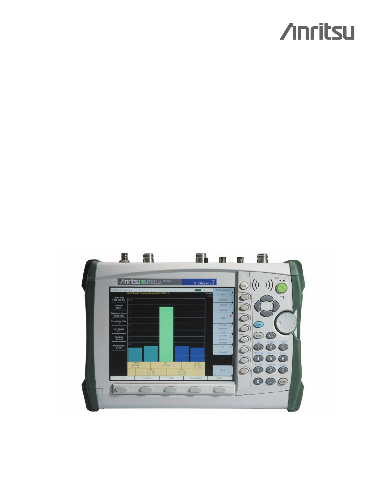
A High Performance – Handheld
Base Station Analyzer
MT8222A
BTS Master
Introduction
High performance handheld base station analyzer with a complete set of measurement tools, spectrum analyzer, cable and
antenna analysis, power meter, Bit Error Rate Tester for communication backhaul, supports multiple modulation formats
GSM/GPRS/EDGE, W-CDMA/HSDPA, CDMA/EVDO, WiMAX 802.16d/802.16e, TD-SCDMA, LTE and GPS.
High Performance Highlights
™
• SpectrumAnalyzer100kHzto7.1GHz
• 2portCable&AntennaAnalyzer
10 MHz to 4 or 6 GHz
• HighAccuracyPowerMeter±0.16dB
• 4kg(9.0lbs)
• BitErrorRateTesterE1,T1&T3
• InterferenceAnalyzer
• Channelscanner
• GPSreceiveroption
• 2and2.5Gmodulationoptions
GSM/GPRS/EDGE,IS-95
• PIMAnalyzer
• 3GModulationoptionsW-CDMA/
HSDPA, 1xrtt/EVDO and TD-SCDMA
• 3.5GmodulationoptionsLTE,
802.16d and 802.16e
• 2.5–3hourbatterylife
The Anritsu MT8222A is the most advanced ultra-portable base station analyzer on the market,
featuring unparalleled performance at a modest price.
Page 2

Specifications
Cable and Antenna Analyzer
Frequency Range: 10 MHz to 4 GHz
Frequency Range (Option 26): 10 MHz to 6 GHz
Frequency Accuracy: 25 ppm
Frequency Resolution: 10 kHz
Data Points: Low, Medium, High (137/275/551)
Interference Immunity: On-Channel: +17 dBm
1-Port Power: High: 0 dBm (typical)
2-Port Power: High: 0 dBm (typical)
Low: –35 dBm (typical)
Corrected Directivity: 42 dB (10 MHz to 6 GHz)
1-Port Accuracy:
= <0.8 + 20 log (1 ±10
System Dynamic Range: 80 dB, 10 MHz to 3 GHz
Return Loss: Range: 0 to 60 dB
Resolution: 0.01 dB
VSWR: Range: 1 to 65
Resolution: 0.01
Cable Loss: Range: 0 to 30 dB
Resolution: 0.01 dB
1-Port Phase: Range: –180° to +180°
Resolution: 0.01°
Smith Chart: Resolution: 0.01
2-Port Gain: Range: –120 to 100 dB
Resolution: 0.01 dB
2-Port Phase: Range: –180° to +180°
Resolution: 0.01°
Distance-to-Fault: Fault Resolution (meters): (1.5 x 10
the propagation constant and ∆F is F2-F1 in Hz
Horizontal Range (meters): 0 to (data points-1) x Fault
Resolution to a maximum of 1500m (4921 ft.)
where datapoints = 137/275/551
Vertical Range (Return Loss): 0 to 60 dB
Vertical Range (VSWR): 1 to 65
(All other specs remain the same)
On-Frequency: 0 dBm (RF Out) +30 dBc RF In
–E∆/20
) dB, typical E∆ = Directivity – Measured Return Loss
70 dB, > 3 GHz to 5.5 GHz
65 dB, > 5.5 GHz to 6 GHz
8
x vp)/∆F vp is
Spectrum Analyzer
Frequency:
Frequency: 100 kHz to 7.1 GHz
Maximum Continuous Input: +30 dBm
Tuning Resolution: 1 Hz
Frequency Reference: Aging: ± 1 ppm/10 years
Frequency Span: 10 Hz to 7.1 GHz plus 0 Hz (zero span)
Sweep Time: Minimum 100 ms, 10 µs to 600 seconds (zero span)
Sweep Trigger: Free run, Single, Video, External
Resolution Bandwidth: (–3 dB width) ± 10%, 1 Hz to 3 MHz in
Video Bandwidth: (–3 dB) 1 Hz to 3 MHz in 1–3 sequence
SSB Phase Noise: –100 dBc/Hz max at 10, 20 and 30 kHz offset from
Amplitude:
Measurement Range: DANL to +30 dBm
Absolute amplitude accuracy Power Levels
≥–50 dBm, ≤35 dB input attenuation,
Preamplifier Off: 100 kHz to ≤ 10 MHz ± 1.5 dB
Displayed Average Noise Level (DANL in 1 Hz RBW, 0 dB attenuation,
Reference level –50 dBm, preamp on):
Frequency Typical Max
10 MHz to 1 GHz –163 dBm –161 dBm
> 1 GHz to 2.2 GHz –160 dBm –159 dBm
> 2.2 GHz to 2.8 GHz –156 dBm –153 dBm
> 2.8 GHz to 4.0 GHz –160 dBm –159 dBm
> 4.0 GHz to 7.1 GHz –158 dBm –154 dBm
Accuracy: ± 0.3 ppm (25 °C ± 25 °C) + aging
1–3 sequence 8 MHz demodulation bandwidth
carrier –102 dBc/Hz max at 100 kHz offset from carrier
> 10 MHz to 4 GHz ± 1.25 dB
> 4 GHz to 7.1 GHz ± 1.75 dB
Input-Related Spurious:
(–30 dBm input, 0 dB input attenuation, Span < 1.7 GHz)
–70 dBc typical –60 dBc max*
* Exceptions:
Input Frequency Spur Level
1674 MHz –38 dBc (–48 typical)
Residual Spurious:
(Preamplifier on, RF input terminated, 0 dB input attenuation)
–100 dBm max
(Preamplifier off, RF input terminated, 0 dB input attenuation)
–90 dBm max**, 100 kHz to <3200 MHz
–84 dBm max**, 3200 to 7100 MHz
** Exceptions:
Frequency Max Spur Level (Typical)
250, 300, and 350 MHz –85 dBm
~4010 MHz –80 dBm (–90 dBm)
~5084 MHz –70 dBm (–83 dBm)
~5894 MHz –75 dBm (–87 dBm)
~7028 MHz –80 dBm (–92 dBm)
Display Range: 1 to 15 dB/div in 1 dB steps. Ten divisions displayed
Amplitude Units Log Scale Modes: dBm, dBV, dBmv, dBµV
Attenuator Range: 0 to 65 dB
Attenuator Resolution: 5 dB steps
Power Meters:
Frequency Range: 10 MHz to 7.1 GHz
Display Range: –80 dBm to +80 dBm
Measurement Range: –60 dBm to +30 dBm
Offset Range: 0 to +60 dB
Accuracy:
–40 dBm < Max ≤ +15 dBm:
10 MHz –4 GHz: ± 1.25 dB
4 GHz –7.1 GHz: ± 1.75 dB
Max > +15 dBm:
10 MHz –6.5 GHz: ± 1.75 dB
6.5 GHz –7 GHz: ± 2 dB
Max ≤ –40 dBm:
10 MHz –4 GHz: ± 1.5 dB
4 GHz –7.1 GHz: ± 1.75 dB
VSWR: 1.5:1 typical
Maximum Power: +30 dBm (1 W) without external attenuator
W-CDMA/HSDPA RF Measurements (Option 44)
Frequency Ranges:
Bands I - IX
RF Channel Power
(Temperature range 15 ºC to 35 ºC):
± 0.7 dB typical
(± 1.25 dB max)
Occupied Bandwidth Accuracy: ± 100 kHz
Residual Adjacent Channel
Leakage Ratio (ACLR)1
(824 to 894 MHz, 1710 to 2170):
–54 dB typical at 5 MHz offset
–59 dB typical at 10 MHz offset
Leakage Ratio (ACLR)1 (2300-2700 MHz):
–54 dB typical at 5 MHz offset
–57 dB typical at 10 MHz offset
ACLR Accuracy (Single Channel Active)
(824 to 894 MHz, 1710 to 2170):
± 0.8 dB for ACLR ≥ –45 dB at 5 MHz offset
± 0.8 dB for ACLR ≥ –50 dB at 10 MHz offset
ACLR Accuracy (Single Channel Active)
(2300-2700 MHz):
± 1.0 dB for ACLR ≥ –45 dB at 5 MHz offset
± 1.0 dB for ACLR ≥ –50 dB at 10 MHz offset
Frequency Error: ± 10 Hz + Time Base Error,
99% confidence level:
± 10 Hz + Time Base Error, 99% confidence level
2
Page 3

W-CDMA Demodulation and W-CDMA/HSDPA
Demodulator (Options 45 and 65)
EVM Accuracy (824 to 894 MHz, 1710 to 2170 MHz):
(3GPP Test Model 4) ± 2.5%; 6% ≤ EVM ≤ 25%
(3GPP Test Model 5) ± 2.5%; 6% ≤ EVM ≤ 20%
(2300 MHz to 2700 MHz)
EVM Accuracy: ± 2.5% for 6% ≤ EVM ≤ 20%
Residual EVM: 2.5% typical
Code Domain Power: ± 0.5 dB for code channel power > –25 dB
CPICH (dBm) Accuracy: ± 0.8 dB typical
Scrambling Code: 3 seconds
16, 32, 64 DCPH (test model 1)
16, 32 DCPH (test model 2, 3)
W-CDMA/HSDPA OTA (Option 35)
Resolution: 0.1 dB
Power Monitor (Option 5) (requires external sensor)
Display Range: –80 to +80 dBm (10 pW to 100 kW)
Measurement Range: –40 dBm to +20 dBm (10 nW to 40 mW)
Offset Range: 0 to +60 dB
Resolution: 0.1 dB or 0.1W
Accuracy: ± 1 dB for >–40 dBm using 560-7N50 detector
Bias Tee (Option 10A)
Voltage Range: +12V to +32V
Current (Low/High): 250 mA/450 mA, 1 A surge for 100 ms
Resolution: 0.1 V
Interference Analyzer (Option 25)
Strength of the Interferer: Locate the Interferer
RSSI: Collect data up to 72 hours
Spectrogram: Collect data up to 72 hours
Signal ID:
Monitors one particular frequency or scan the span and identify up to 12 signals.
Identifies CDMA, GSM and WCDMA signals with Signal-to-noise ratio greater
than 10 dB.
Channel Scanner (Option 27)
Frequency Range: 100 KHz to 7.1 GHz
Frequency Accuracy:
±10 Hz + Time base error, 99% Confidence level
Measurement Range: +20 dBm to –110 dBm
Channel Power:
100 kHz to ≤ 10 MHz ± 1.5 dB
> 10 MHz to 4 GHz ± 1.25 dB
> 4 GHz to 7.1 GHz ± 1.75 dB
Adjacent Channel Power Accuracy: ± 0.75 dB
GPS (Option 31)
GPS Location Indicator:
Latitude, Longitude and Altitude on display
Latitude, Longitude and Altitude with trace storage
GPS High Frequency Accuracy
when GPS antenna is connected:
± 25 ppb with GPS ON, 3 minutes after satellite lock
Internal High Accuracy, when
GPS antenna is not connected:
Better than ± 50 ppb for 3 days from a High Accuracy GPS Lock and
within 0 ºC to 50 ºC ambient temperature
1
Channel power accuracy will vary with amount of data burst traffic
GSM/GPRS/EDGE RF Measurements (Option 40)
Occupied Bandwidth: Bandwidth within which 99% of the power transmitted
Burst Power: ± 1 dB typical for –50 dBm to +20 dBm (± 1.5 dB max)
Frequency Error: ± 10 Hz + time base error, 99% confidence level
on a single channel lies
GSM/GPRS/EDGE Demodulator (Option 41)
GSMK Modulation Quality (RMS Phase) Measurement Accuracy: ± 1 deg
Residual Error (GSMK): 1 deg
8PSK Modulation Quality (EVM) Measurement Accuracy: ± 1.5%
Residual Error (8PSK): 2.5%
CDMA – RF Measurements (Option 42)
and EVDO RF Measurements (Option 62)
Channel Power Accuracy: ± 1 dB typical for RF Input from +20 dBm
to –50 dBm (± 1.5 dB maximum)
cdmaOne and CDMA2000 1xRTT Demodulator
(Option 43)
Residual Rho: > 0.995 typical for RF Input from +20 dBm to –50 dBm
Rho Accuracy: ± 0.005 for Rho > 0.9
Frequency Error: ± 10 Hz + Time base error, 99% confidence level
PN Offset: with 1 x 64 chips
Pilot Power Accuracy: ± 1 dB typical, relative to Channel Power
Tau: ± 0.5 µs typical (± 1 µs maximum)
(> 0.99 dB maximum)
(in slow mode)
EVDO Demodulator (Option 63)
Demodulator Measurements are EVDO Rev A compatible.
Residual Rho: > 0.995 typical for RF Input from +20 dBm to –50 dBm
Rho Accuracy: ± 0.01 for Rho > 0.9
Frequency Error: ± 20 Hz + Time base error, 99% confidence level
PN Offset: within 1 x 64 chips
Pilot Power Accuracy: ± 1 dB typical relative to Channel Power
Tau: ± 0.5 µs typical (± 1 µs maximum)
(> 0.99 dB maximum)
cdmaOne and CDMA2000 1xRTT Over The Air
(Option 33) and EVDO Over The Air (Option 34)
Over The Air Measurement: Nine strongest pilots with Tau and Ec/Io.
Fixed WiMAX RF Measurements (Option 46)
Channel Power Accuracy
Six multipaths relative to strongest pilot.
1
: ± 1 dB Typical for +20 dBm to –50 dBm
(± 1.5 dB max)
Fixed WiMAX Demodulator (Option 47)
Residual EVM (rms): 3% for +20 dBm to –50 dBm (3.5% max.)
Frequency Error: ± 0.1 ppm + time base error, 99% confidence level
Mobile WiMAX Specifications
Bandwidths: 3.5 MHz, 5 MHz, 7 MHz 8.75 MHz, 10 MHz
Frame Length: 5 ms, 10 ms
Zone Types: PUSC
DL-MAP Support:
Regular and Compressed Map, DIUC support
DL-MAP Auto Decoding: Convolutional Coding (CC), Convolution Turbo Coding (CTC)
Mobile WiMAX Over the Air (OTA) Measurements
(Option 37)
Time Interval: 1 sec – 60 sec
Measurement Duration: 72 hours max
Auto Save: Yes
GPS Logging: Yes
Mobile WiMAX RF Measurements (Option 66)
Channel Power Accuracy: ± 1 dB Typical (± 1.5 dB max)
for +20 dBm to –50 dBm
Mobile WiMAX Demodulator (Option 67)
For +20 dBm to –50 dBm, Residual EVM (rms): 2.5% typical (3% max),
Frequency Error: ± 0.02 ppm + time base error, 99% confidence level
at –50 dBm on FCH
3
Page 4

TD-SCDMA RF Measurements (Option 60)
Channel Power (RRC): ± 1 dB typical, 1.5 dB max
(slot power from +10 dBm to -40 dBm)
TD-SCDMA Demodulator (Option 61)
Residual EVM (rms): 3% typical (for P-CCPCH slot, slot power > –50 dBm)
Freq Error Accuracy: ± 10 Hz typical + time base error (in the presence of a
downlink slot)
Timing Error (Tau) for dominant SYNC-DL code: ± 0.2 μs (external trigger)
Supported Modulation: QPSK
Spreading Factor: 1, 16
TD-SCDMA Over the Air (OTA) Measurements
(Option 38)
32 codes displaying Ec/Io, Tau
Frequency Error:
± 0.02 ppm + time base error, 99% confidence level
T1 Bit-Error-Rate-Tester (BERT), (Option 51)
T1 Analyzer, Fractional T1 and sub-channels BER testing at 1.544 MB, 64, 16
and 8 kB rates
Line Coding: AMI, B8ZS
Framing Modes: D4 (Superframe), ESF (Extended Superframe)
Connection Configurations: Terminate: 100 Ω
Bridge: ≥ 1000 Ω
Monitor: Connect via 20 dB pad in DSX
Receiver Sensitivity: Terminate: +6 dB to –36 dB
Bridge: +6 dB to –36 dB
Monitor: 20 dB flat gain
Transmit Level: 0 dB, –7.5 dB, and –15 dB Clock
Sources: External Bits Clock
Internal: 1.544 MHz ± 5 ppm
Pulse Shapes: Conform to ANSI T1.403 and ITU G.703
Pattern Generation and Detection: PRBS: 2-9, 2-11, 2-15, 2-20, 2-23
Inverted and non-inverted
QRSS, 1-in-8 (1-in-7), 2-in-8, 3-in-24,
All ones, All zeros, T1-Daly,
User defined (≤ 32 bits)
Circuit Status Reports: Carrier present, Frame ID and Sync.,
Pattern ID and Sync.
Alarm Detection: AIS (Blue Alarm), RAI (Yellow Alarm)
Error Detection: Frame Bits, Bit, BER, BPV, CRC
Error Sec Error Insertion: Bit, BPV, Framing Bits, RAI, AIS
Loopback Modes: Self loop, CSU, NIU, User defined,
In-band or Data Link
Level Measurements: Vp-p (± 5%), can also display in dBdsx
Data Log: Continuous, up to 72 hrs
T1 Frequency Measurement: ± 5 ppm
DS0 Channel Access: Tone Generator
Frequency: 100 Hz to 3000 Hz
Level: –30 to 0 dBm, with 1 dB steps
VF Measurement: Frequency: 100 Hz to 3000 Hz, ± 3 Hz
Level: –40.0 to +3.0 dBm, ± 0.2 dBm
Audio Monitor: Manually select channel 1 to 24
ITU G-821 Analysis: Error seconds (ES), error free seconds (EFS),
severely errored seconds (SES), unavailable seconds (UAS),
available seconds (AS), degrade minutes (DGRM)
E1 - 2 MB/s Bit-Error-Rate-Tester (BERT),
(Option 52)
E1 - 2 MB/s Analyzer, sub-channnels
BER testing: BER testing at 2.048 MB, 64, 16 and 8 kB rates
Line Coding: AMI, HDB3
Framing Modes: PCM30, PCM30CRC-4, PCM31, PCM31CRC-4
Connection Configurations: Terminate: 75 Ω BNC unbalanced, 120 Ω
RJ48C balanced
Bridge: > 1000 Ω
Monitor: Connect via 20 dB pad in DSX
Receiver Sensitivity: Terminate: +6 dB to –43 dB
Bridge: +6 dB to –43 dB
Monitor: 20 dB flat gain
Clock Sources: External: Sets clock,
Internal: 2.048 MHz ± 5 ppm
Pulse Shapes: Conform to ITU G.703
Pattern Generation and Detection: PRBS: 2-9, 2-11, 2-15, 2-20, 2-23
Inverted and non-inverted
QRSS, 1-in-8 (1-in-7), 2-in-8, 3-in-24,
All ones, All zeros, User defined ≤ 32 bits)
Circuit Status Reports: Carrier present, Frame ID and Sync.,
Pattern ID and Sync.
Alarm Detection: AIS, RAI, MFAS RAI (PCM-30)
Error Detection: Frame Bits, BER (FAS), Bit, CRC-4, E-Bits, BPV
Error Analysis: Error rates, Error Counts
ITU G-821 Analysis: Errored seconds, error free seconds,
severely errored seconds, unavailable seconds,
available seconds, degraded minutes
Error Insertion: E-bit, Framing Bits (FAS), RAI, AIS
Loopback Modes: Self loopback
Level Measurements: Vp-p (± 5%)
Data Log: Continuous, up to 72 hrs
E1 - 2 MB/s Frequency Measurement: ± 5 ppm
VF Tone Generator:
Frequency: 100 Hz to 3000 Hz
Level: –30 to 0 dBm with 1 dB steps
Audio Monitor: manually select channel 1-31
VF Measurement:
Frequency: 100 Hz to 3000 Hz ± 3 Hz
Level: –40.0 to +3.0 dBm ± 0.2 dBm
T3/T1/FT1 Bit-Error-Rate-Tester (BERT),
(Option 053)
T3 Analyzer
Line Coding: B3ZS, AMI
Framing Modes: Unframed, M13, C-bit
Connection Configurations: Terminate (75 Ω) BNC unbalanced
Monitor (Connect via 20 dB pad in DSX)
Receiver Sensitivity: +6 dB to –24 dB
Transmit Level: DSX, Low, Pulse shape: conforms to ITU G.703
Clock Sources: External, Internal: 44.736 MHz ± 5 ppm
Pulse Shapes: Conform to ANSI T1.102 & ITU G.703
Pattern Generation and Detection: PRBS: 2-9, 2-11, 2-15, 2-20, 2-23
Inverted and non-inverted,
User defined (≤ 32 bits)
Circuit Status Reports: Carrier present, Frame ID and Sync.,
Pattern ID and Sync.
Alarm Detection: AIS (Blue Alarm), RAI (Yellow Alarm)
Error Detection: Frame Bits, Bit, BER, BPV, FEBE,
C-bit, P-bit, Error Sec
Error Insertion: Bit, Framing Bits
Loopback Modes: Stuff Bit (M13 & C-bit): 1 of DS1
FEAC (C-bit): DS3, 1 of DS1 all DS1
Level Measurements: Vp-p (± 5%), can also display in dBdsx
Data Log: Continuous, up to 72 hrs
T3 Frequency Measurement: ± 5 ppm
ITU G-821 Analysis: Errored seconds, error free seconds,
severely errored seconds, unavailable seconds,
available seconds, degraded minutes 32 bits)
4
Page 5

T1 Analyzer, Fractional T1 and sub-channels
BER Testing: BER testing at 1.544 MB, 64, 16 and 8 kB rates
Line Coding: AMI, B8ZS
Framing Modes: D4 (Superframe), ESF (Extended Superframe)
Connection Configurations: Terminate: 100 Ω balanced, Bantam
Bridge: ≤ 1000 Ω
Monitor: Connect via 20 dB pad in DSX
Receiver Sensitivity: Terminate: +6 dB to –36 dB
Bridge: +6 dB to –36 dB
Monitor: 20 dB flat gain
Transmit Level: 0 dB, –7.5 dB, and –15 dB
Clock Sources: External Bits clock,
Internal: 1.544 MHz ± 5 ppm
Pulse Shapes: Conform to ANSI T1.403 & ITU G.703
Pattern Generation and Detection:
PRBS: 2-9, 2-11, 2-15, 2-20, 2-23 Inverted and
non-inverted, QRSS, 1-in-8 (1-in-7), 2-in-8, 3-in-24,
All ones, All zeros, T1-Daly, User defined (≤ 32 bits)
Circuit Status Reports:
Carrier present, Frame ID and Sync.,
Pattern ID and Sync.
Alarm Detection: AIS (Blue Alarm), RAI (Yellow Alarm)
Error Detection: Frame Bits, Bit, BER, BPV, CRC, Error Sec
Error Insertion: Bit, BPV, Framing Bits, RAI, AIS
Loopback Modes: Self loop, CSU, NIU, User defined,
In-band or Data Link
Level Measurements: Vp-p (± 5%), can also display in dBdsx
Data Log: Continuous, up to 72 hrs
T1 Frequency Measurement: ± 5 ppm
DS0 Channel Access: Tone Generator Frequency: 100 Hz to 3000 Hz
Level: –30 to 0 dBm, with 1 dB steps
VF Measurement: Frequency: 100 Hz to 3000 Hz, ± 3 Hz
Level: –40.0 to +3.0 dBm, ± 0.2 dBm
Audio Monitor: Manually select channel 1 to 24
ITU G-821 Analysis: Errored seconds, error free seconds,
severely errored seconds, unavailable seconds,
available seconds, degraded minutes
Gated Sweep (Option 090)
The option adds gated sweep to the spectrum analyzer mode, giving the
user the capability to view pulsed or burst signals only when they are on,
or conversely look at the spectrum only when a signal is off.
Trigger Signal: External TTL input, user selectable high or low level.
Gate Delay: 0 to 65 ms typical
Gate Length: 1 µs to 65 ms typical
PIM Analyzer Specifications (Option 0419)
(requires PIM Master™)
See Product Brochure 11410-00546
LTE Specifications
Bandwidth: 10 MHz
Span: 1.4, 3, 5, 10, 15, 20 MHz
Frame Length: 2.5, 5.0, 10.0 msec
LTE RF Measurements (Option 0541)
RF Channel Power Accuracy: ± 1.0 dB typical, (RF input −50 to +10 dBm)
LTE Modulation Measurements (Option 0542)
Frequency Error: ± 10 Hz + time base error, 99% confidence level
Residual EVM (rms): 2.5 % typical (E-UTRA Test Model 3.1)
(RF Input -50 dBm to +10 dBm
LTE Over-the-Air (OTA) Measurements
(Option 0546)
Scanner: Six strongest Sync Signals
Auto Save: Yes
GPS Tagging and Logging: Yes
System
Measurement Resolution: 0.01 dB
Offset Range: ± 60 dB
Interfaces: USB A/mini-B 2.0
General Specifications
Maximum Continuous Input into Spectrum Analyzer:
10 dB attenuation, +30 dBm, ± 50 VDC
RF Input VSWR: 2.0:1 maximum, 1.5:1 typical (≥ 10 dB attenuation)
Internal Time Base Accuracy: ± 0.3 ppm
Interfaces:
Type N female RF Connector
Type N female RF Out Port and RF In Port (50 Ω)
BNC female connectors for external reference
and external trigger
Reverse BNC connector for GPS antenna
E1-2Mb/s (Receive and Transmit): RJ48 (75 Ω) connector and BNC(f) (120 Ω)
T1 (Receive and Transmit): Bantam Jack (100 Ω)
T1, T3 (Receive and Transmit): Bantam Jack (100 Ω) and BNC (75 Ω)
RF Detector: Type N(m) 50 Ω
RJ45 connector for Ethernet 10/100-Base T
2.5 mm 3-wire cellular headset connector
5-pin Mini-B USB 2.0 device connector
USB 2.0 Host connector used with PSN50
and USB Flash Drives
Maximum Input (Damage Level) into Cable and Antenna Analyzer Test Port:
Type N: +23 dBm, ± 50 VDC
Environmental: MIL-PRF-28800F Class 2
Operating: –10 ºC to 55 ºC, humidity 85%
Storage: –51 ºC to 71 ºC
Altitude: 4600 meters, operating and non-operating
Safety: Conforms to EN 61010-1 for Class 1 portable equipment
Electromagnetic Compatibility: Meets European Community requirements for
CE marking
Size: 315 x 211 x 94 mm (12.4 x 8.3 x 3.7 in.)
Weight: 4 kg (9 lbs.)
* Excludes mismatch errors.
Excludes noise, zero set, zero drift for levels <–20 dBm.
Excludes digital modulation uncertainty between +17 and +20 dBm.
**After 30 min warm-up
5
Page 6

Ordering Information
Model
MT8222A - BTS Master
100 kHz to 7.1 GHz
Standard
Cable and Antenna Analyzer
Frequency Range: 10 MHz to 4 GHz
Spectrum Analyzer
Frequency Range: 100 kHz to 7.1 GHz
Power Meter
Frequency Range: 100 kHz to 7.1 GHz
Optional
Interference Analyzer
Frequency Range: 100 kHz to 7.1 GHz
Channel Scanner
Frequency Range: 100 kHz to 7.1 GHz
W-CDMA/HSDPA Analyzer
Frequency Range: 824 to 894 MHz, 1710 to 2170 MHz, and 2300 to 2700 MHz
GSM/GPRS/EDGE Analyzer
Frequency Range: 380 to 400 MHz, 410 to 430 MHz, 450 to 468 MHz,
478 to 496 MHz, 698 to 746 MHz, 747 to 792 MHz, 806 to 866 MHz,
824 to 894 MHz, 890 to 960 MHz, 880 to 960 MHz, 876 to 960 MHz,
870 to 921 MHz, 1710 to 1990 MHz
Fixed WiMAX Analyzer
Frequency Range: 2.3 to 2.7 GHz, 3.3 to 3.8 GHz, 5.25 to 5.875 GHz
Mobile WiMAX Analyzer
Frequency Range: 2.3 to 2.7 GHz, 3.3 to 3.8 GHz
CDMA Analyzer
Frequency Range: 1 MHz to 2.7 GHz
EVDO Analyzer
Frequency Range: 1 MHz to 2.7 GHz
TD-SCDMA Analyzer
Frequency Range: 400 MHz to 2.7 GHz
Options
MT8222A-005 Power Monitor (requires external detector)**
MT8222A-010 Bias Tee variable voltage
MT8222A-10A High Voltage Bias Tee
MT8222A-019 High Accuracy Power Meter (PSN50 sensor not included)
MT8222A-025 Interference Analysis
MT8222A-026 6 GHz Cable and Antenna Analyzer (10 MHz to 6 GHz)
MT8222A-027 Channel Scanner
MT8222A-028 CW Signal Generator (requires CW Signal Generator kit)
MT8222A-031 GPS Recei ver (includes GPS antenna,
Anritsu part number: 2000-1410)
MT8222A-033 cdmaOne and CDMA2000 1xRTT Over The Air (OTA)****
MT8222A-034 EVDO Over the Air (OTA)****
MT8222A-035 W-CDMA/HSDPA (OTA)****
MT8222A-037 Mobile WiMAX Over The Air (OTA) Measurements
MT8222A-038 TD-SCDMA Over The Air (OTA) Measurements
MT8222A-040 GSM/GPRS/EDGE RF Measurement
MT8222A-041 GSM/GPRS/EDGE Demodulation
MT8222A-042 CDMA RF Measurements
MT8222A-043 cdmaOne and CDMA2000 1xRTT Demodulator
MT8222A-044 W-CDMA/HSDPA RF Measurement
MT8222A-045 W-CDMA Demodulation
MT8222A-046 Fixed WiMAX RF Measurement
MT8222A-047 Fixed WiMAX Demodulation
MT8222A-051 T1/FT1 BERT (Bit-Error-Rate-Tester)**
MT8222A-052 E1-2 Mb/s Bit-Error-Rate-Tester (BERT)**
MT8222A-053 T3/T1/FT1 BERT (Bit-Error-Rate-Tester)**
MT8222A-060 TD-SCDMA RF Measurement
MT8222A-061 TD-SCDMA Demodulation
MT8222A-062 EVDO RF Measurements
MT8222A-063 EVDO Demodulator
MT8222A-064 DVB-T/H Digital Video Measurement
MT8222A-065 W-CDMA/HSDPA Demodulation***
MT8222A-066 Mobile WiMAX RF Measurements
MT8222A-067 Mobile WiMAX Demodulator
MT8222A-090 Gated Sweep
MT8222A-0419 PIM Analyzer (requires PIM Master™)
MT8222A-0541 LTE RF Measurements
MT8222A-0542 LTE Modulation Measurements
MT8222A-0546 LTE Over-the-Air Measurements
****
High Accuracy Power Meter Accessories
PSN50 High Accuracy Power Sensor, 50 MHz to 6 GHz
MA24106A High Accuracy Power Sensor, 50 MHz to 6 GHz
3-2000-1498 USB A/mini-B cable 10 ft
3-1010-122 Attenuator (Bi-directional), 20 dB, 5 watt,
3-1010-123 Attenuator (Bi-directional), 30 dB, 50 watt,
3-1010-124 Attenuator (Uni-directional), 40 dB, 100 watt,
DC to 12.4 GHz, N(m) to N(f)
DC to 8.5 GHz, N(m) to N(f)
DC to 8.5 GHz, N(m) to N(f)
Standard Accessories
10920-00060 Handheld Instruments Documentation Disc
10580-00156 BTS Master™ User’s Guide
11410-00433 BTS Master MT8222A Technical Data Sheet
65681 Soft Carrying Case
2300-498 Master Software Tools
2300-530 Anritsu Tool Box with Line Sweep Tools
633-44 Rechargeable Li-Ion Battery
40-168-R AC/DC Adapter
806-141-R Automotive Cigarette Lighter/12 Volt DC Adapter
3-2000-1567 512 MB Compact Flash Memory Module
2000-1520-R USB Flash Drive
3-2000-1360 USB A/mini-B cable 6 ft.
3-806-152 Cross-over Ethernet cable
1091-27-R Adapter, DC to 18 GHz, N(m) to SMA(f), 50 Ω
1091-172-R Adapter, DC to 1.3 GHz, N(m) to BNC(f), 50 Ω
One Year Warranty (Including battery, firmware, and software
Certificate of Calibration and Conformance
Optional Accessories
800-109 Detector Extender Cable, 7.6 m (25 ft.)
800-111 Detector Extender Cable, 30.5 m (100 ft.)
2000-1374 Dual External, Li-Ion Charger with Universal
2000-1410 Magnet Mount GPS Antenna with 3 m (15 ft) Cable
3-2000-1567 512 MB Compact Flash Memory Module
2000-1520-R USB Flash Drive
760-243-R Transit Case for Anritsu MT8222A BTS Master
1N50C Limiter, N(m) to N(f), 50 Ω, 10 MHz to 18 GHz
790-641 Cable Lock
42N50-20 Attenuator, 20 dB, 5 watt, DC to 18 GHz, N(m) to N(f)
42N50A-30 Attenuator, 30 dB, 50 watt, DC to 18 GHz, N(m) to N(f)
22N50 Open/Short, DC to 18 GHz, N(m), 50 Ω
22NF50 Open/Short, DC to 18 GHz, N(f), 50 Ω
SM/PL-1 Precision Load, DC to 6 GHz, 42 dB, N(m), 50 Ω
SM/PLNF-1 Precision Load, DC to 6 GHz, 42 dB, N(f), 50 Ω
OSLN50-1 Precision Open/Short/Load, DC to 6 GHz, 42 dB,
OSLNF50-1 Precision Open/Short/Load, DC to 6 GHz, 42 dB,
2000-767-R Precision Open/Short/Load, DC to 4 GHz,
2000-768-R Precision Open/Short/Load, DC to 4 GHz,
1091-26-R N(m) to SMA(m) DC to 18 GHz, 50 Ω
1091-27-R N(m) to SMA(f) DC to 18 GHz, 50 Ω
1091-80-R N(f) to SMA(m) DC to 18 GHz, 50 Ω
1091-81-R N(f) to SMA(f) DC to 18 GHz, 50 Ω
*All the options are upgradeable at Service Centers except T1 option.
**Option 5 and Options 51, 52 and 53 are mutually exclusive.
***Option 65 includes Option 45.
****Requires Option 31 GPS
6
Power Supply
50 Ω, N(m)
50 Ω, N(f)
7/16 DIN(m), 50 Ω
7/16 DIN(f), 50 Ω
Page 7

Adapters
510–90-R 7/16 DIN(f) to N(m), DC to 7.5 GHz, 50 Ω
510–91-R 7/16 DIN(f) to N(f), DC to 7.5 GHz, 50 Ω
510–92-R 7/16 DIN(m) to N(m), DC to 7.5 GHz, 50 Ω
510–93-R 7/16 DIN(m) to N(f), DC to 7.5 GHz, 50 Ω
510–96-R 7/16 DIN(m) to 7/16 DIN(m), DC to 7.5 GHz, 50 Ω
510–97-R 7/16 DIN(f) to 7/16 DIN(f), DC to 7.5 GHz, 50 Ω
510–102-R N(m) to N(m), DC to 11 GHz, 50 Ω, 90º right angle
Precision Adapters
34NN50A Precision Adapter, N(m) to N(m), DC to 18 GHz, 50 Ω
34NFNF50 Precision Adapter, N(f) to N(f), DC to 18 GHz, 50 Ω
Directional Antennas
2000-1411-R Portable Yagi Antenna, 10 dBd, N(f), 822 to 900 MHz
2000-1412-R Portable Yagi Antenna, 10 dBd, N(f), 885 to 975 MHz
2000-1413-R Portable Yagi Antenna, 10 dBd, N(f), 1.71 to 1.88 GHz
2000-1414-R Portable Yagi Antenna, 9.3 dBd, N(f), 1.85 to 1.99 GHz
2000-1415-R Portable Yagi Antenna, 10 dBd, N(f), 2.4 to 2.5 GHz
2000-1416-R Portable Yagi Antenna, 10 dBd, N(f), 1.92 to 2.17 GHz
GPS Antenna
2000-1410 Magnet Mount GPS Antenna with 15 ft. cable
Portable Antennas
2000-1200-R 806 MHz to 866 MHz, SMA(m), 50 Ω
2000-1030-R 1.71 GHz to 1.88 GHz, SMA(m), 50 Ω (1/2 wave)
2000-1031-R 1.85 GHz to 1.99 GHz, SMA(m), 50 Ω (1/2 wave)
2000-1032-R 2.4 GHz to 2.5 GHz, SMA(m), 50 Ω (1/2 wave)
2000-1035-R 896 MHz to 941 MHz, SMA(m), 50 Ω (1/2 wave)
2000-1361-R 2.4 GHz to 2.5 GHz, 5 GHz to 6 GHz, SMA(m), 50 Ω
2000-1473-R 870 MHz to 960 MHz, SMA(m), 50 Ω
2000-1474-R 1.71 GHz to 1.88 GHz with knuckle elbow (1/2 wave)
2000-1475-R 1.92 GHz to 1.98 GHz and 2.11 GHz to 2.17 GHz,
SMA(m), 50 Ω
2000-1636-R Antenna Kit (Consists of: 2000-1030-R, 2000-1031-R,
2000-1032-R, 2000-1200-R, 2000-1035-R, 2000-1361-R,
and carrying pouch)
Attenuator
42N50A-30 30 dB, 50 W, Bi-directional, DC to 18 GHz, N(m) to N(f)
Cables
806-16-R Bantam Plug to Bantam Plug
3-806-116 Bantam Plug to BNC
3-806-117 Bantam “Y” Plug to RJ48
3-806-169 72-inch (1.8 m), BNC to BNC,
75.5 RG59 Type Coax Cable
806-176-R Bantam Plug to Alligator Clips
806-177-R RJ48 to RJ48
Band Pass Filters
1030-105-R 890 to 915 MHz Band, N(m) to N(f), 50 Ω
1030-106-R 1710 to 1790 MHz Band, N(m) to N(f), 50 Ω
1030-107-R 1910 to 1990 MHz Band, N(m) to N(f), 50 Ω
1030-109-R 824 to 849 MHz Band, N(m) to SMA(f), 50 Ω
1030-110-R 880 to 915 MHz Band, N(m) to SMA(f), 50 Ω
1030-111-R 1850 to 1910 MHz Band, N(m) to SMA(f), 50 Ω
1030-112-R 2400 to 2484 MHz Band, N(m) to SMA(f), 50 Ω
1030-114-R 806 to 869 MHz Band, N(m) to SMA(f), 50 Ω
Test Port Cable Armored
15NN50-1.5C 1.5 meters, N(m) to N(m), 6 GHz, 50 Ω
15NNF50-1.5B 1.5 meters N(m) to N(f), 18 GHz, 50 Ω
15NN50-3.0C 3.0 meters, N(m) to N(m), 6 GHz, 50 Ω
15NN50-5.0C 5.0 meters, N(m) to N(m), 6 GHz, 50 Ω
15NNF50-1.5C 1.5 meters, N(m) to N(f), 6 GHz, 50 Ω
15NNF50-3.0C 3.0 meters, N(m) to N(f), 6 GHz, 50 Ω
15NN50-5.0C 5.0 meters, N(m) to N(m), 6 GHz, 50 Ω
15ND50-1.5C 1.5 meters, N(m) to 7/16 DIN(m), 6 GHz, 50 Ω
15NDF50-1.5C 1.5 meters, N(m) to 7/16 DIN(f), 6 GHz, 50 Ω
Power Monitor Detectors
560-7N50B 0.01 to 20 GHz
560-7S50B 0.01 to 20 GHz
560-7K50 0.01 to 40 GHz
560-7VA50 0.01 to 50 GHz
CW Signal Generator Kit
67276 CW Signal Generator Kit (includes the 4 parts listed below)
65-54 Attenuator, 0-90 dB (1 dB and 10 dB steps),
2.5 GHz, N(f), N(f)
510-102-R Adaptor, N(m) to N(m), DC to 11 GHz, 50 Ω,
90º right angle
SC7651 Power Splitter, 50 Ω, N(f), N(m), N(f)
67263 Cable, N(m), N(m)
7
Page 8

The Master Users Group is an organization dedicated to providing training, technical support, networking opportunities
and links to Master product development teams. As a member you will receive the Insite Quarterly Newsletter with user
stories, measurement tips, new product news and more.
Visit us to register today: www.anritsu.us/smiusignup
To receive a quote to purchase a product or order accessories visit our online ordering site: www.ShopAnritsu.com
Training at Anritsu
Anritsu has designed courses to help you stay up to date with technologies important to your job.
For available training courses visit: www.anritsu.com/training
Anritsu Corporation
5-1-1 Onna, Atsugi-shi, Kanagawa, 243-8555 Japan
Phone: +81-46-223-1111
Fax: +81-46-296-1238
• U.S.A.
Anritsu Company
1155 East Collins Boulevard, Suite 100,
Richardson, TX, 75081 U.S.A.
Toll Free: 1-800-ANRITSU (267-4878)
Phone: +1-972-644-1777
Fax: +1-972-671-1877
• Canada
Anritsu Electronics Ltd.
700 Silver Seven Road, Suite 120, Kanata,
Ontario K2V 1C3, Canada
Phone: +1-613-591-2003
Fax: +1-613-591-1006
• Brazil
Anritsu Electrônica Ltda.
Praça Amadeu Amaral, 27 - 1 Andar
01327-010 - Bela Vista - São Paulo - SP - Brasil
Phone: +55-11-3283-2511
Fax: +55-11-3288-6940
• Mexico
Anritsu Company, S.A. de C.V.
Av. Ejército Nacional No. 579 Piso 9, Col. Granada
11520 México, D.F., México
Phone: +52-55-1101-2370
Fax: +52-55-5254-3147
• U.K.
Anritsu EMEA Ltd.
200 Capability Green, Luton, Bedfordshire LU1 3LU, U.K.
Phone: +44-1582-433280
Fax: +44-1582-731303
• France
Anritsu S.A.
12 Avenue du Québec,
Bâtiment Iris 1-Silic 638,
91140 VILLEBON SUR YVETTE, France
Phone: +33-1-60-92-15-50
Fax: +33-1-64-46-10-65
• Germany
Anritsu GmbH
Nemetschek Haus, Konrad-Zuse-Platz 1
81829 München, Germany
Phone: +49 (0) 89 442308-0
Fax: +49 (0) 89 442308-55
• Italy
Anritsu S.p.A.
Via Elio Vittorini, 129, 00144 Roma, Italy
Phone: +39-06-509-9711
Fax: +39-06-502-2425
• Sweden
Anritsu AB
Borgafjordsgatan 13, 164 40 KISTA, Sweden
Phone: +46-8-534-707-00
Fax: +46-8-534-707-30
• Finland
Anritsu AB
Teknobulevardi 3-5, FI-01530 VANTAA, Finland
Phone: +358-20-741-8100
Fax: +358-20-741-8111
• Denmark
Anritsu A/S (for Service Assurance)
Anritsu AB (for Test & Measurement)
Kirkebjerg Allé 90 DK-2605 Brøndby, Denmark
Phone: +45-7211-2200
Fax: +45-7211-2210
• Russia
Anritsu EMEA Ltd.
Representation Office in Russia
Tverskaya str. 16/2, bld. 1, 7th floor.
Russia, 125009, Moscow
Phone: +7-495-363-1694
Fax: +7-495-935-8962
• United Arab Emirates
Anritsu EMEA Ltd.
Dubai Liaison Office
P O Box 500413 - Dubai Internet City
Al Thuraya Building, Tower 1, Suite 701, 7th Floor
Dubai, United Arab Emirates
Phone: +971-4-3670352
Fax: +971-4-3688460
• Singapore
Anritsu Pte. Ltd.
60 Alexandra Terrace, #02-08, The Comtech (Lobby A)
Singapore 118502
Phone: +65-6282-2400
Fax: +65-6282-2533
• India
Anritsu Pte. Ltd.
India Branch Office
3rd Floor, Shri Lakshminarayan Niwas, #2726, 80 ft Road,
HAL 3rd Stage, Bangalore - 560 075, India
Phone: +91-80-4058-1300
Fax: +91-80-4058-1301
• P. R. China (Hong Kong)
Anritsu Company Ltd.
Units 4 & 5, 28th Floor, Greenfield Tower, Conco rdia Plaza,
No. 1 Science Museum Road, Tsim Sha Tsui East,
Kowloon, Hong Kong, P.R. China
Phone: +852-2301-4980
Fax: +852-2301-3545
• P. R. China (Beijing)
Anritsu Company Ltd.
Beijing Representative Office
Room 2008, Beijing Fortune Building,
No. 5 , Dong-San-Huan Bei Road,
Chao-Yang District, Beijing 100004, P.R. China
Phone: +86-10-6590-9230
Fax: +86-10-6590-9235
• Korea
Anritsu Corporation, Ltd.
8F Hyunjuk Bldg. 832-41, Yeoksam-Dong,
Kangnam-ku, Seoul, 135-080, Korea
Phone: +82-2-553-6603
Fax: +82-2-553-6604
• Australia
Anritsu Pty Ltd.
Unit 21/270 Ferntree Gully Road, Notting Hill
Victoria, 3168, Australia
Phone: +61-3-9558-8177
Fax: +61-3-9558-8255
• Taiwan
Anritsu Company Inc.
7F, No. 316, Sec. 1, Neihu Rd., Taipei 114, Taiwan
Phone: +886-2-8751-1816
Fax: +886-2-8751-1817
® Anritsu All trademarks are registered trademarks of
their respective companies. Data subject to change
without notice. For the most recent specifications visit:
www.us.anritsu.com
Technical Data Sheet No. 11410-00433, Rev. F Printed in United States 2010-12
©2010 Anritsu Company. All Rights Reserved
 Loading...