

Page 1
Technical Data Sheet
™
BTS Master
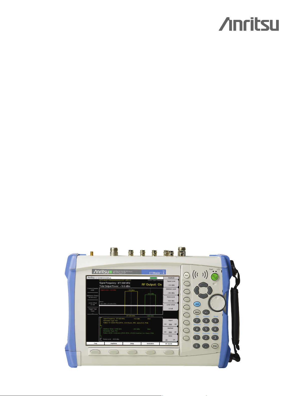
High Performance
Handheld Base Station Analyzer
MT8221B
400 MHz to 4.0 GHz Cable & Antenna Analyzer
150 kHz to 7.1 GHz Spectrum Analyzer
Introduction
Anritsu introduces its next generation high performance handheld Base Station Analyzer for installation and maintenance of
wireless networks. The BTS Master features a future-proof platform with 20 MHz demodulation bandwidth capability for
Signal Analysis of upcoming 4G standards and a Vector Signal Generator for receiver testing.
Cable and Antenna Analyzer Highlights
Measurements: RL, VSWR, Cable Loss, DTF, Phase, Gain•
2-port Gain Measurement Uncertainty: < 0.45 dB•
2-port Dynamic Range: > 80 dB•
RF Immunity: +17 dBm on-channel, +10 dBm on-frequency•
Calibration: OSL and FlexCal™•
Bias Tee: 32 V internal•
Capabilities and Functional Highlights
GSM/EDGE•
W-CDMA/HSDPA•
TD-SCDMA/HSDPA•
CDMA, EV-DO•
WiMAX - Fixed, Mobile•
Vector Signal Generator•
Zero-span IF Output•
Gated Sweep•
GPS tagging of stored traces•
Internal Preamplifier standard•
Spectrum and Interference Analyzer Highlights
Measurements: Occupied Bandwidth, Channel Power, ACPR, C/I•
Interference Analyzer: Spectrogram, Signal Strength, RSSI, Signal ID•
Dynamic Range: > 95 dB in 1 Hz RBW•
DANL: -163 dBm in 1 Hz RBW•
Phase Noise: -100 dBc/Hz @ 10 kHz offset•
Frequency Accuracy: < ±25 ppb with GPS On•
Internal Power Meter•
High Accuracy Power Meter•
4, 6, 8, 18 GHz USB Sensors•
Channel Scanner•
8.4” Display•
E1, T1, T3 Backhaul Analyzer•
< 5 minute warm-up time•
2.5 hour battery operation time•
Ethernet/USB Data Transfer •
MST Remote Access Tool•
BTS Master™ MT8221B Base Station Analyzer featuring Vector Signal Generator
Handheld Size: 315 x 211 x 94 mm (12.4 x 8.3 x 3.7 in), Lightweight: 4.9 kg (10.7 lbs)
Page 2

BTS Master™ MT8221B Base Station Analyzer Specifications
Cable and Antenna Analyzer
Measurements
Measurements VSWR 1-port Phase
Return Loss 2-port Phase
Cable Loss 2-port Gain
Distance-to-Fault (DTF) Return Loss Smith Chart
Distance-to-Fault (DTF) VSWR
Setup Parameters
Frequency Start/Stop, Signal Standard, Start Cal
DTF Start/Stop, DTF Aid, Units (m/ft), Cable Loss, Propagation Velocity, Cable, Windowing
Windowing Rectangular, Normal Side Lobe, Low Side Lobe, Minimum Side Lobe
Amplitude Top, Bottom Auto Scale, Full Scale
Sweep Run/Hold, Single/Continuous, RF Immunity (High/Low), Data Points, Averaging/Smoothing,
Data Points 137, 275, 551
Markers Markers 1-6 each with a Delta Marker, Marker to Peak/Valley, Marker Table (On/Off )
Traces Recall, Copy to Display Memory, No Trace Math, Trace ± Memory, Trace Overlay (On/Off)
Limit Line On/Off, Single Limit, Multi-segment (41), Limit Alarm, Clear
Limit Line Edit Frequency, Amplitude, Add Point, Delete Point, Next Point Left/Right, Move Limit
Calibration Start Cal, 1/2-port, Low/High Power, Standard/FlexCal™, DUT Connector, Congure DUT
Save/Recall Setups, Measurements, Screen Shots Jpeg (save only)
Delete Selected File, All Measurements, All Mode Files, All Content
Directory Management Sort Method (Name/Type/Date), Ascend/Descend, Internal/USB, Copy, Format USB
Application Options
Frequency
Frequency Range 400 MHz to 4 GHz
Frequency Accuracy ±3.0 ppm
Frequency Resolution 1 kHz (RF immunity low)
Output Power
High -7 dBm, typical, 1 or 2-port
Low -40 dBm, typical, 2-port
Dynamic Range
400 MHz to 3.0 GHz 80 dB
>3.0 GHz to 4.0 GHz 70 dB
Interference Immunity
On-Channel +17 dBm @ >1.0 MHz from carrier frequency
On-Frequency +10 dBm within ±10 kHz from the carrier frequency
Measurement Speed
Return Loss ≤4.5 msec/data point, RF immunity low, typical
Distance-to-Fault ≤4.5 msec/data point, RF immunity low, typical
Return Loss
Measurement Range 0 to 60 dB
Resolution 0.01 dB
VSWR
Measurement Range 1 to 65
Resolution 0.01
Cable Loss
Measurement Range 0 to 30 dB
Resolution 0.01 dB
2-Port Gain
Measurement Range -120 to 100 dB
Resolution 0.01 dB
Output Power (High/Low)
File Save, Recall, Delete, Directory Management
Bias-Tee (On/Off), Impedance (50Ω, 75Ω, Other)
100 kHz (RF immunity high)
Page 2 of 24
Page 3
BTS Master™ MT8221B Base Station Analyzer Specifications
Cable and Antenna Analyzer (continued)
Distance-to-Fault
Vertical Range Return Loss 0 to 60 dB
Vertical Range VSWR 1 to 65
Fault Resolution (meters) (1.5 x 10⁸ x vp)/∆F (vp = velocity propagation constant, ∆F is F2-F1 in Hz)
Horizontal Range (meters) 0 to (Data Points-1) x Fault Resolution, to a maximum of 1500 meters (4921 ft)
Phase (1 and 2-Port)
Measurement Range -180° to +180°
Resolution 0.01°
Smith Chart
Resolution 0.01
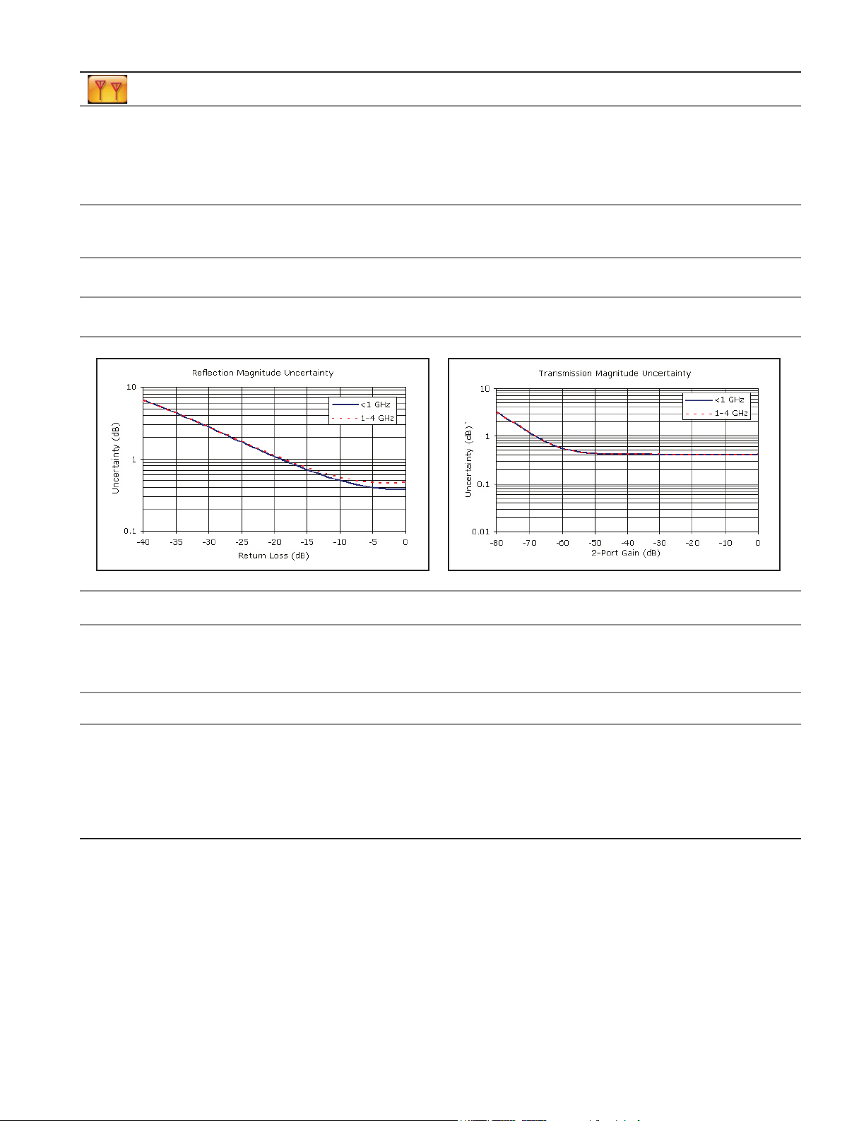
Measurement Accuracy
Corrected Directivity >42 dB
Measurement Uncertainty
Bias-Tee (Option 0010)
Setup On/Off, Voltage, Current (Low/High)
Voltage Range +12 to +32 V
Current (Low/High) 250 mA/450 mA, 1 A surge for 100 ms
Resolution 0.1 V
GPS Receiver Option (Option 0031) (Antenna sold separately, P/N 2000-1528-R)
Setup On/Off, Antenna Voltage 3.3/5.0 V, GPS Info
GPS Time/Location Indicator Time, Latitude, Longitude and Altitude on display
High Frequency Accuracy Spectrum Analyzer, Interference Analyzer, Signal Analyzers
when GPS Antenna is connected <±25 ppb with GPS On, 3 minutes after satellite lock in selected mode
GPS Lock – after antenna is disconnected <±50 ppb for 3 days, 0 ºC to 50 ºC ambient temperature
Connector SMA, female
Time, Latitude, Longitude and Altitude with trace storage
Page 3 of 24
Page 4

BTS Master™ MT8221B Base Station Analyzer Specifications
Spectrum Analyzer
Measurements
Smart Measurements Field Strength (uses antenna calibration tables to measure dBm/m2 or dBmV/m)
Occupied Bandwidth (measures 99% to 1% power channel of a signal)
Channel Power (measures the total power in a specied bandwidth)
ACPR (adjacent channel power ratio)
AM/FM/SSB Demodulation (wide/narrow FM, upper/lower SSB), (audio out only)
C/I (carrier-to-interference ratio)
Setup Parameters
Frequency Center/Start/Stop, Span, Frequency Step, Signal Standard, Channel #
Amplitude Reference Level (RL), Scale, Attenuation Auto/Level, RL Offset, Pre-Amp On/Off, Detection
Span Span, Span Up/Down (1-2-5), Full Span, Zero Span, Last Span
Bandwidth RBW, Auto RBW, VBW, Auto VBW, RBW/WBW, Span/RBW
File Save, Recall, Delete, Directory Management
Save/Recall Setups, Measurements, Limit Lines, Screen Shots Jpeg (save only), Save-on-Event
Save-on-Event Crossing Limit Line, Sweep Complete, Save-then-Stop, Clear All
Delete Selected File, All Measurements, All Mode Files, All Content
Directory Management Sort Method (Name/Type/Date), Ascend/Descend, Internal/USB, Copy, Format USB
Application Options Bias-Tee (On/Off), Impedance (50Ω, 75Ω, Other)
Sweep Functions
Sweep Single/Continuous, Manual Trigger, Reset, Detection, Minimum Sweep Time, Trigger Type,
Detection Peak, RMS, Negative, Sample, Quasi-peak
Triggers Free Run, External, Video, Change Position, Manual
Trace Functions
Traces Up to three Traces (A, B, C), View/Blank, Write/Hold, Trace A/B/C Operations
Trace A Operations Normal, Max Hold, Min Hold, Average, # of Averages, (always the live trace)
Trace B Operations
Trace C Operations
Marker Functions
Markers Markers 1-6 each with a Delta Marker, or Marker 1 Reference with Six Delta Markers,
Marker Types Style (Fixed/Tracking), Noise Marker, Frequency Counter Marker
Marker Auto-Position Peak Search, Next Peak (Right/Left), Peak Threshold %, Set Marker to Channel,
Marker Table 1-6 markers frequency and amplitude plus delta markers frequency offset and amplitude
Limit Line Functions
Limit Lines Upper/Lower, On/Off, Edit, Move, Envelope, Advanced, Limit Alarm, Default Limit
Limit Line Edit Frequency, Amplitude, Add Point, Add Vertical, Delete Point, Next Point Left/Right
Limit Line Move To Current Center Frequency, By dB or Hz, To Marker 1, Offset from Marker 1
Limit Line Envelope Create Envelope, Update Amplitude, Number of Points (41), Offset, Shape Square/Slope
Limit Line Advanced Type (Absolute/Relative), Mirror, Save/Recall
Frequency
Frequency Range 150 kHz to 7.1 GHz (usable to 0 Hz)
Maximum Continuous Input +30 dBm
Tuning Resolution 1 Hz
Frequency Reference Aging: ±1.0 ppm/10 years
Frequency Span Accuracy: ±0.3 ppm (25 °C ±25 °C) + aging
Sweep Time Minimum 100 ms, 10 µs to 600 seconds in zero span
Sweep Time Accuracy ±2% in zero span
Bandwidth
Resolution Bandwidth (RBW) 1 Hz to 3 MHz in 1–3 sequence ±10% (1 MHz max in zero-span) (–3 dB bandwidth)
Video Bandwidth (VBW) 1 Hz to 3 MHz in 1–3 sequence (–3 dB bandwidth)
RBW with Quasi-Peak Detection 200 Hz, 9 KHz, 120 kHz (-6 dB bandwidth)
VBW with Quasi-Peak Detection Auto VBW is On, RBW/VBW = 1
Gated Sweep (see Option 0090)
A B, BC, Max Hold, Min Hold
A C, BC, Max Hold, Min Hold, A - B C, B - A C, Relative Reference (dB), Scale
Marker Table (On/Off), All Markers Off
Marker Frequency to Center, Delta Marker to Span, Marker to Reference Level
10 Hz to 7.1 GHz including zero span
Page 4 of 24
Page 5

BTS Master™ MT8221B Base Station Analyzer Specifications
Spectrum Analyzer (continued)
Spectral Purity
SSB Phase Noise –100 dBc/Hz @ 10, 20 and 30 kHz offset from carrier
Amplitude Ranges
Dynamic Range >95 dB (600 MHz, 3.5 GHz), 2/3 (TOI-DANL) in 1 Hz RBW
Measurement Range DANL to +30 dBm
Display Range 1 to 15 dB/div in 1 dB steps, ten divisions displayed
Reference Level Range -120 dBm to +30 dBm
Attenuator Resolution 0 to 65 dB, 5.0 dB steps
Amplitude Units Log Scale Modes: dBm, dBV, dBmv, dBμV
Amplitude Accuracy (Power level >-50 dBm)
(Input attenuation)
150 kHz to ≤10 MHz ±1.50 dB ±1.50 dB ±1.50 dB
150 kHz to 4.0 GHz ±1.50 dB
>10 MHz to 4.0 GHz ±1.25 dB ±1.75 dB ±1.75 dB
>4.0 GHz to 6.5 GHz ±1.75 dB ±1.75 dB
>4.0 GHz to 7.1 GHz ±1.75 dB ±1.75 dB
>6.5 GHz to 7.1 GHz ±2.00 dB ±3.00 dB
Displayed Average Noise Level (DANL)
(DANL in 1 Hz RBW, 0 dB attenuation) Maximum Typical Maximum Typical
150 kHz to 1.0 GHz -137 dBm -150 dBm -161 dBm -163 dBm
>1.0 GHz to 2.2 GHz -133 dBm -147 dBm -159 dBm -160 dBm
>2.2 GHz to 4.0 GHz -133 dBm -143 dBm -156 dBm -159 dBm
>4.0 GHz to 7.1 GHz -130 dBm -138 dBm -154 dBm -156 dBm
Spurs
Residual Spurs Preamp Off (RF input terminated, 0 dB input attenuation)
Exceptions -70 dBm @ 3200 MHz
Exceptions -95 dBm @ 50, 100, 150 MHz
Input-Related Spurious (0 dB attenuation, -30 dBm input, span <1.7 GHz, carrier offset >4.5 MHz)
Exceptions -40 dBc, -60 dBc typical @ 1672 MHz
Third-Order Intercept (TOI)
600 MHz +8 dBm typical
3.5 GHz +9 dBm typical
Second Harmonic Distortion
Preamp Off –50 dBc max
VSWR
<4.0 GHz 1:5:1 typical
4.0 GHz to 7.1 GHz 1.8:1 typical
–102 dBc/Hz @ 100 kHz offset from carrier
Linear Scale Modes: nV, μV, mV, V, kV, nW, μW, mW, W, kW
Preamp Off
(≤35 dB)
Preamp Off
(Reference level -20 dBm)
-90 dBm, 150 kHz to 3.2 GHz
-84 dBm, >3.2 GHz to 7.1 GHz
Preamp On (RF input terminated, 0 dB input attenuation)
-100 dBm. 10 MHz to 7.1 GHz
-60 dBc, -70 dBc typical
Preamp Off
–70 dBc typical
Preamp Off
(40 to 55 dB)
Preamp Off
(60 to 65 dB)
(Reference level -50 dBm)
Preamp On
Preamp On
(0 or 10 dB)
Page 5 of 24
Page 6

BTS Master™ MT8221B Base Station Analyzer Specifications
Power Meter (Option 0029)
Frequency Center/Start/Stop, Span, Frequency Step, Signal Standard, Channel #, Full Band
Amplitude Maximum, Minimum, Offset, Relative On/Off, Units, Auto Scale
Average Acquisition Fast/Med/Slow, # of Running Averages
Limits Limit On/Off, Limit Upper/Lower
Frequency Range 10 MHz to 7.1 GHz
Span 1 kHz to 100 MHz
Display Range -140 dBm to +30 dBm, ≤40 dB span
Measurement Range -120 dBm to +30 dBm
Offset Range 0 to +100 dB
VSWR 1.5:1 typical
Maximum Power +30 dBm without attenuator
Accuracy Same as Spectrum Analyzer
Application Options Impedance (50 Ω, 75 Ω, Other)
High Accuracy Power Meter (Option 0019) (Requires external USB Power Sensor(s))
Amplitude Maximum, Minimum, Offset, Relative On/Off, Units, Auto Scale
Average # of Running Averages, Max Hold
Zero/Cal Zero On/Off, Cal Factor (Center Frequency, Signal Standard)
Limits Limit On/Off, Limit Upper/Lower
Power Sensor Model PSN50 MA24104A MA24106A MA24108A MA24118A
Description High Accuracy
RF Power Sensor
Frequency Range 50 MHz to 6 GHz 600 MHz to 4 GHz 50 MHz to 6 GHz 10 MHz to 8 GHz 10 MHz to 18 GHz
Connector Type N(m), 50 Ω Type N(m), 50 Ω Type N(m), 50 Ω Type N(m), 50 Ω Type N(m), 50 Ω
Dynamic Range -30 to +20 dBm
(.001 to 100 mW)
VBW 100 Hz 100 Hz 100 Hz 50 kHz 50 kHz
Measurand True-RMS True-RMS True-RMS True-RMS,
Measurement Uncertainty ±0.16 dB
Datasheet
11410-00414 11410-00483 11410-00424 11410-00504 11410-00504
(for complete specications)
Notes: 1) Total RSS measurement uncertainty (0 ºC to 50 ºC) for power measurements of a CW signal greater than -20 dBm with
zero mismatch errors.
2) Expanded uncertainty with K=2 for power measurements of a CW signal greater than +20 dBm with a matched load.
Measurement results referenced to the input side of the sensor.
3) Expanded uncertainty with K=2 for power measurements of a CW signal greater than-20 dBm with zero mismatch errors.
1
Inline High
Power Sensor
+3 to +51.76 dBm
(2 mW to 150 W)
±0.17 dB
2
High Accuracy
RF Power Sensor
-40 to +23 dBm
(0.1 µW to 200 mW)
±0.16 dB
1
Microwave USB
Power Sensor
-40 to +20 dBm
(0.1 µW to 100 mW)
Slot Power,
Burst Average
Power
±0.18 dB
3
Microwave USB
Power Sensor
-40 to +20 dBm
(0.1 µW to 100 mW)
True-RMS,
Slot Power,
Burst Average
Power
±0.18 dB
3
Page 6 of 24
Page 7

BTS Master™ MT8221B Base Station Analyzer Specifications
Interference Analyzer (Option 0025)
Measurements Spectrum
Field Strength
Occupied Bandwidth
Channel Power
Adjacent Channel Power (ACPR)
AM/FM/SSB Demodulation (Wide/Narrow FM, Upper/Lower SSB), (audio out only)
Carrier-to-Interference ratio (C/I)
Spectrogram (Collect data up to one week)
Signal Strength (Gives visual and aural indication of signal strength)
Received Signal Strength Indicator (RSSI) (collect data up to one week)
Gives visual and aural indication of signal strength
Signal ID (up to 12 signals)
Center Frequency
Bandwidth
Signal Type (FM, GSM, W-CDMA, CDMA, Wi-Fi)
Closest Channel Number
Number of Carriers
Application Options Signal-to-Nose Ratio (SNR) >10 dB
Bias-Tee (On/Off), Impedance (50 Ω, 75 Ω, Other)
Channel Scanner (Option 0027)
Number of Channels 1 to 20 Channels (Power Levels)
Measurements Graph/Table, Max Hold (On/5 sec/Off), Frequency/Channel, Current/Maximum, Dual Color
Scanner Scan Channels, Scan Frequencies, Scan Customer List, Scan Script Master™
Amplitude Reference Level, Scale
Custom Scan Signal Standard, Channel, # of Channels, Channel Step Size, Custom Scan
Frequency Range 150 kHz to 7.1 GHz
Frequency Accuracy ±10 Hz + Time base error
Measurement Range -110 dBm to +30 dBm
Application Options Bias-Tee (On/Off), Impedance (50 Ω, 75 Ω, Other)
Gated Sweep (Option 0090)
Mode Spectrum Analyzer, Sweep
Trigger External TTL
Setup Gated Sweep (On/Off)
Zero Span IF Output (Option 0089)
Mode Spectrum Analyzer/Span/Zero Span
Center Frequency 140 MHz ± 130 kHz
Output Level -25 dBm typical
Reference Level -57 to +30 dBm (Preamp Off)
IF Bandwidths Up to 30 MHz (3 dB bandwidth)
Connector BNC female
Gate Polarity (Rising, Falling)
Gate Delay (0 to 65 ms typical)
Gate Length (1 µs to 65 ms typical)
Zero Span Time
-87 to -40 dBm (Preamp On)
Page 7 of 24
Page 8

BTS Master™ MT8221B Base Station Analyzer Specifications
Vector Signal Generator Option (Option 0023)
Setup Parameters
Frequency Frequency, Signal Standard, Channel Number, Interferer Offset
Amplitude Signal/Interferer/Noise Level in dBm, Level Offset,
Trigger (for modulated signals) Type (None/Positive/Negative), Delay, Manual, Pattern Manager
Pattern Manager Add, Erase
Modulation Signal Pattern Select, Interferer Pattern Select, Edit
Modulation Edit Analog, Digital, Custom, Spectrum Inversion (Normal/Reverse)
Active Pattern Memory 256 MB
Frequency Range 400 MHz to 6 GHz
Frequency Resolution 1 Hz
Frequency Accuracy ±0.3 ppm (25 °C ±25 °C) + aging
Output Power -124 to 0 dBm, CW
Step Size 0.1 dB nominal
Bandwidth 1 signal to 10 MHz or 2 signals to 5 MHz each + AWGN
Waveform Addition Desired Signal + Interfering Signal + AWGN
Level Accuracy, Single Channel
(At least 30 minutes warm-up after 1 hour non-operating at 15 to 35 °C ambient, excludes load VSWR effects)
VSG Output Power CW Mode W-CDMA CW Mode W-CDMA CW Mode W-CDMA
-46 to 0 dBm ±1.0 dB ±1.2 dB ±1.2 dB
-46 to -8 dBm ±1.4 dB ±1.4 dB ±1.8 dB
-84 to <-46 dBm ±1.1 dB ±1.4 dB ±1.3 dB ±1.4 dB ±1.3 dB ±2.0 dB
-104 to <-84 dBm ±1.4 dB ±1.5 dB ±1.4 dB ±1.5 dB ±1.4 dB ±2.0 dB
-124 to <-104 dBm ±1.7 dB ±1.7 dB ±1.7 dB ±1.7 dB ±1.7 dB ±2.4 dB
Standard Signal Patterns
EDGE – Continuous 3Pi/8-8PSK, 270.833 ksym/sec, Linearized Gaussian ltered, Data = PN9
W-CDMA Pilot QPSK, 3.84 Msym/s, RRC ltered, alpha=0.22, Data = PN9
DECT 16 QAM – Continuous 1.152 Msym/s, RRC ltered, alpha = 0.5, Data = PN9
DECT 64 QAM – Continuous 16 QAM, 6.84 Msym/s. RRC ltered, alpha = 0.15, Data = PN9
DVB-C 1.152 Msym/s, RRC ltered, alpha = 0.5, Data = PN9
J.83C Digital Cable 16 QAM, 5 Msym/s, RRCC ltered, alpha = 0.13
64 QAM – US Digital Cable 5.056941 Msym/s, RRC ltered, alpha = 0.18
User-defined Signal Patterns
Input Waveform for MST Pattern
Converter
Number of Waveforms ≤1000
Sampling Rate Bandwidth Time Length
12.500 MHz 10.0 MHz ≤ 4 seconds N x 8 Samples
6.250 MHz 5.0 MHz ≤ 8 seconds N x 4 Samples
1.625 MHz 1.2 MHz ≤32 seconds N x 4 Samples
Signal (CW/Modulated/Off), Interferer (CW/Modulated/Off), Noise (On/Off )
RF On/Off
-124 to -8 dBm, Modulated/Noise/Multicarrier
(400 MHz to 2.0 GHz) (>2.0 to 4.0 GHz) (>4.0 to 6.0 GHz)
ASCII Text or MATLAB® le format
Page 8 of 24
Page 9

BTS Master™ MT8221B Base Station Analyzer Specifications
TD-SCDMA/HSDPA Signal Analyzers (Options 0060, 0061, 0038)
Measurements
RF
(Option 0060)
Channel Spectrum
Channel Power
Occupied Bandwidth
Left Channel Power
Left Channel Occ B/W
Right Channel Power
Right Channel Occ B/W
Power vs. Time
Six Slot Powers
Channel Power (RRC)
DL-UL Delta Power
UpPTS Power
DwPTS Power
On/Off Ratio
Slot Peak-to-Average Power
Spectral Emission
Setup Parameters
Scrambling/Midamble Code Auto, 0-127
Measurement Speed Fast, Normal, Slow
Measurement Summary Screens Overall Measurements, RF Measurements, Signal Quality Measurements
RF Measurements (Option 0060)
RF Channel Power Accuracy (RRC) ±1.5 dB, ±1.0 dB typical, (slot power -40 to +10 dBm)
Demodulation (Option 0061)
Supported Modulation QPSK, 8 PSK, 16 QAM
Residual EVM (rms) 3% typical, P-CCPH slot power >-50 dBm
Pilot Power Accuracy ±1.0 dB typical
Timing Error (Tau) for Dominant SYNC-DL ±0.2 µs (external trigger)
Over-the-Air (OTA) Measurements (Option 0038)
Code Domain Power/Error
Slot Selection Auto, 0-6
SYNC-DL Code Auto, 0-31
Maximum Users Auto, 2, 4, 6, 8, 10, 12, 14, 16
User Selectable Uplink Switch Point, Number of Carriers (1, 3), Tau Offset
Demodulation Type Auto, QPSK, 8 PSK, 16 QAM
Frequency Center, Signal Standard, Channel #, Closest Channel, Decrement/Increment Channel
Save/Recall Setup, Measurement, Screen Shot (save only), to Internal/External Memory
Frequency Error ±20 Hz + time base error, in the presence of a downlink slot
Spreading Factor 1, 16
Code Scanner 32 Sync Codes and associated Scrambling Code Groups
Tau Scanner Six strongest Sync Codes
Auto Save Yes
GPS Logging Yes
Demodulation
(Option 0061)
(QPSK/8 PSK/16 QAM)
Slot Power
DwPTS Power
Noise Floor
Frequency Error
Tau
Scrambling Code
EVM
Peak EVM
Peak Code Domain Error
Trigger Trigger Type (No Trigger/GPS/External), External Trigger (Rising/Falling), Tau Offset
Amplitude Scale/Division, Power Offset, Auto Range, Adjust Range, Units (dBm/Watts)
Sweep Hold/Run, Trigger Sweep
PN Offset Within 1 x 64 chips
Over-the-Air (OTA)
(Option 0038)
Code Scan (32)
Scrambling Code Group
Tau
Ec/I
o
Pilot Dominance
Tau Scan (Six)
Sync-DL#
Tau
Ec/I
o
DwPTS Power
Pilot Dominance
Occupied Bandwidth
Channel Power
Channel Power RCC
On/Off Ratio
Peak-to-Average Ratio
Frequency Error
EVM
Peak EVM
Peak Code Domain Error
Tau
Noise Floor
Pass/Fail
(User Editable)
Page 9 of 24
Page 10

BTS Master™ MT8221B Base Station Analyzer Specifications
GSM/GPRS/EDGE Signal Analyzers (Options 0040, 0041)
Measurements
RF
(Option 0040)
Channel Spectrum
Channel Power
Occupied Bandwidth
Burst Power
Average Burst Power
Frequency Error
Modulation Type
BSIC (NCC, BCC)
Multi-channel Spectrum
Power vs. Time (Frame/Slot)
Channel Power
Occupied Bandwidth
Burst Power
Average Burst Power
Frequency Error
Modulation Type
BSIC (NCC, BCC)
Setup Parameters
GSM/EDGE Select Auto, GSM, EDGE
Measurement Summary Screens Overall Measurements, RF Measurements, Signal Quality Measurements
RF Measurements (Option 0040)
Frequency Error ±10 Hz + time base error, 99% confidence level
Occupied Bandwidth Bandwidth within which 99% of the power transmitted on a single channel lies
Burst Power Error ±1.5 dB, ±1 dB typical, (–50 dBm to +20 dBm)
Demodulation (Option 0041)
GSMK Modulation Quality (RMS Phase)
Measurement Accuracy
Residual Error (GSMK) 1 deg
8 PSK Modulation Quality (EVM)
Measurement Accuracy
Residual Error (8 PSK) 2.5%
Phase Error
EVM
Origin Offset
C/I
Modulation Type
Magnitude Error
BSIC (NCC, BCC)
Frequency Center, Signal Standard, Channel #, Closest Channel, Decrement/Increment Channel
Save/Recall Setup, Measurement, Screen Shot (save only), to Internal/External Memory
Demodulation
(Option 0041)
Amplitude Power Offset, Auto Range, Adjust Range
Sweep Single/Continuous, Trigger Sweep
±1 deg
±1.5%
Over-the-Air (OTA) Pass/Fail
There are no additional OTA
Measurements.
RF Measurements and
Demodulation can be made OTA
Channel Power
Occupied Bandwidth
Burst Power
Average Burst power
Frequency Error
Phase Error
EVM
Origin Offset
C/I
Magnitude Error
(User Editable)
Page 10 of 24
Page 11

BTS Master™ MT8221B Base Station Analyzer Specifications
W-CDMA/HSDPA Signal Analyzers (Options 0044, 0045 or 0065, 0035)
Measurements
RF
(Option 0044)
Band Spectrum
Channel Spectrum
Channel Power
Occupied Bandwidth
Peak-to-Average Power
Spectral Emission Mask
Single carrier ACLR
Multi-carrier ACLR
Setup Parameters
Scrambling Code, Threshold Auto, Manual
Maximum Spreading Factor 256, 512
Measurement Summary Screens Overall Measurements, RF Measurements, Signal Quality Measurements
RF Measurements (Option 0044)
RF Channel Power Accuracy ±1.25 dB, ±0.7 dB typical, (temperature range 15 ºC to 35 ºC)
Occupied Bandwidth Accuracy ±100 kHz
Adjacent Channel Leakage Ratio (ACLR) -54 dB/-59 dB ±0.8 dB @ 5 MHz/10 MHz offset, typical, 824 to 894, 1710 to 2170 MHz
Demodulation (Option 0045 for W-CDMA only or 0065 for W-CDMA and HSDPA)
Code Domain Power ±0.5 dB for code channel power >–25 dB,
CPICH (dBm) Accuracy ±0.8 dB typical
Over-the-Air (OTA) Measurements (Option 0035)
Scrambling Code Scanner Six strongest Scrambling Codes
Code Domain Power Graph
Code Domain Power Table
Codogram
User Selectable Scrambling Code, S-CCPCH Spread, S-CCPCH Code, PICH Code, Threshold,
Frequency Center, Signal Standard, Channel #, Closest Channel, Decrement/Increment Channel
Save/Recall Setup, Measurement, Screen Shot (save only), to Internal/External Memory
Frequency Range Bands I – XIV, XVII
Frequency Error ±10 Hz + time base error, 99% condence level
EVM Accuracy ±2.5%, 6% ≤EVM ≤25%
Residual EVM 2.5%
Multipath Scanner Six multipaths’ power relative to strongest pilot
Demodulation
(Option 0045 or 0065)
P-CPICH Power
Channel Power
Noise Floor
EVM
Carrier Feed Through
Peak Code Domain Error
Carrier Frequency
Frequency Error
Control Channel Power
Abs/Rel/Delta Power
CPICH, P-CCPCH
S-CCPCH, PICH
P-SCH, S-SCH
HSDPA
Power vs. Time
Constellation
Code, Status
EVM, Modulation Type
Power, Code Utilization
Power Amplifier Capacity
Max Amp Power, CPICH Power, Frequency Error Average
Amplitude Scale/Division, Power Offset, Auto Range, Adjust Range, Units (dBm/Watts)
Marker Six Markers, Table On/Off
Sweep Single/Continuous, Trigger Sweep
-54 dB/-57 dB ±1.0 dB @ 5 MHz/10 MHz offset, typical, 2300 to 2700 MHz
16, 32, 64 DCPH (test model 1), 16, 32 DCPH (test model 2, 3)
Over-the-Air (OTA)
(Option 0035)
Scrambling Code Scanner (Six)
Scrambling Codes
CPICH
Ec/I
o
E
c
Pilot Dominance
OTA Total Power
Multipath Scanner (Six)
Six Multipaths
Tau
Distance
RSCP
Relative Power
Multipath Power
Max Output Power
Frequency Error
EVM
CPICH
Occupied Bandwidth
Spectral Mask
ACLR
PCDE
P-CCPCH
S-CCPCH
Code Spread 3
PICH
Code 128
Test Models
1 (16), (32), (64)
2
3 (16), (32)
4 (+CPICH), (-CIPCH)
5 (2 HS), (4 HS), (8 HS)
Pass/Fail
(User Editable)
Page 11 of 24
Page 12

BTS Master™ MT8221B Base Station Analyzer Specifications
cdmaOne/CDMA2000 1X Signal Analyzers (Option 0042, 0043, 0033)
Measurements
RF
(Option 0042)
Channel Spectrum
Channel Power
Occupied Bandwidth
Peak-to-Average Power
Spectral Emission Mask
Multi-carrier ACPR
Setup Parameters
Measurement Speed Fast, Normal, Slow
External Trigger Polarity Rising, Falling
Measurement Summary Screens Overall Measurements, RF Measurements, Signal Quality Measurements
RF Measurements (Option 0042)
RF Channel Power Accuracy ±1.5 dB, ±1.0 dB typical, (RF input -50 to +20 dBm)
Demodulation (Option 0043)
Pilot Power Accuracy ±1.0 dB typical, relative to channel power
Over-the-Air (OTA) Measurements (Option 0033)
Code Domain Power Graph
Code Domain Power Table
Walsh Codes 64, 128
Number of Carriers 1 to 5
Carrier Bandwidth 1.23, 1.24, 1.25 MHz
Frequency Center, Signal Standard, Channel #, Closest Channel, Decrement/Increment Channel
Save/Recall Setup, Measurement, Screen Shot (save only), to Internal/External Memory
Frequency Error ±10 Hz + time base error, 99% condence level (in slow mode)
Rho Accuracy ±0.005, for Rho >0.9
Residual Rho >0.995, typical, >0.99 maximum, (RF input -50 to +20 dBm)
Pilot Scanner Nine strongest pilots
Multipath Scanner Six multipaths’ power relative to strongest pilot
Demodulation
(Option 43)
Pilot Power
Channel Power
Noise Floor
Rho
Carrier Feed Through
Tau
RMS Phase Error
Frequency Error
Abs/Rel/ Power
Pilot
Page
Sync
Q Page
Code
Status
Power
Multiple Codes
Code Utilization
PN Setup PN Trigger (No Trigger, GPS, External), PN Search Type (Auto, Manual), PN Offset
Amplitude Scale/Division, Power Offset, Auto Range, Adjust Range, Units (dBm/Watts)
Sweep Single/Continuous, Trigger Sweep
PN Offset 1 x 64 chips
Tau ±0.5 µs typical, ±1.0 µs maximum
Limit Test Average of ten tests compared to limit
Over-the-Air (OTA)
(0ption 33)
Pilot Scanner (Nine)
PN
Ec/I
o
Tau
Pilot Power
Channel Power
Pilot Dominance
Multipath Scanner (Six)
Ec/I
o
Tau
Channel Power
Multipath Power
Limit Test – 10 Tests Averaged
Rho
Adjusted Rho
Multipath
Pilot Dominance
Pilot Power
Pass/Fail Status
Channel Power
Occupied Bandwidth
Peak-to-Average Power
Spectral Mask Test
Frequency Error
Channel Frequency
Frequency error
Pilot Power
Noise Floor
Rho
Carrier Feed Through
Tau
RMS Phase Error
Code Utilization
Measured PN
Pilot Dominance
Multipath Power
Pass/Fail
(User Editable)
Page 12 of 24
Page 13

BTS Master™ MT8221B Base Station Analyzer Specifications
CDMA2000 1xEV-DO Signal Analyzers (Option 0062, 0063, 0034)
Measurements
RF
(Option 0062)
Channel Spectrum
Channel Power
Occupied Bandwidth
Peak-to-Average Power
Power vs. Time
Pilot & MAC Power
Channel Power
Frequency Error
Idle Activity
On/Off Ratio
Spectral Emission Mask
Multi-carrier ACPR
Setup Parameters
Measurement Speed Fast, Normal, Slow
External Trigger Polarity Rising, Falling
Number of Carriers\ 1 to 5
Measurement Summary Screens Overall Measurements, RF Measurements, Signal Quality Measurements
RF Measurements (Option 0062)
RF Channel Power Accuracy ±1.5 dB, ±1.0 dB typical, (RF input -50 to +20 dBm)
Demodulation (Option 0063)
EV-DO Compatibility Rev 0 and Rev A
Pilot Power Accuracy ±1.0 dB typical, relative to channel power
Over-the-Air (OTA) Measurements (Option 0034)
MAC Code Domain Power Graph
MAC Code Domain Power Table
Data Code Domain Power
Walsh Codes 64, 128
Carrier Bandwidth 1.23, 1.24, 1.25 MHz
Frequency Center, Signal Standard, Channel #, Closest Channel, Decrement/Increment Channel
Save/Recall Setup, Measurement, Screen Shot (save only), to Internal/External Memory
Frequency Error ±10 Hz + time base error, 99% condence level
Rho Accuracy ±0.01, for Rho >0.9
Residual Rho >0.995 typical, >0.99, maximum (RF input -50 to +20 dBm)
Pilot Scanner Nine strongest pilots
Multipath Scanner Six multipaths’ power relative to strongest pilot
Demodulation
(Option 0063)
Pilot & MAC Power
Channel Power
Frequency Error
Rho Pilot
Rho Overall
Data Modulation
Noise Floor
Code
Status
Power
Code Utilization
Active Data Power
Data Modulation
Rho Pilot
Rho Overall
Maximum Data CDP
Minimum Data CDP
PN Setup PN Trigger (No Trigger, GPS, External), PN Search Type (Auto, Manual), PN Offset
Slot Type Auto, Active, Idle
Amplitude Scale/Division, Power Offset, Auto Range, Adjust Range, Units (dBm/Watts)
Sweep Single/Continuous, Trigger Sweep
PN Offset Within 1 x 64 chips
Tau ±0.5 µs typical, ±1.0 µs maximum
Over-the-Air (OTA)
(Option 0034)
Pilot Scanner (Nine)
PN
Ec/I
o
Tau
Pilot Power
Channel Power
Pilot Dominance
Mulitpath Scanner (Six)
Ec/I
o
Tau
Channel Power
Multipath Power
Channel Power
Occupied Bandwidth
Peak-to-Average Power
Carrier Frequency
Frequency Error
Spectral Mask
Noise Floor
Pilot Power
RMS Phase Error
Tau
Code Utilization
Measured PN
Pilot Dominance
Mulitpath Power
Pass/Fail
(User Editable)
Page 13 of 24
Page 14

BTS Master™ MT8221B Base Station Analyzer Specifications
IEEE 802.16 Fixed WiMAX Signal Analyzers (Options 0046, 0047)
Measurements
RF
(Option 0046)
Channel Spectrum
Channel Power
Occupied Bandwidth
Power vs. Time
Channel Power
Preamble Power
Data Burst Power
Crest Factor
ACPR
Setup Parameters
Cyclic Prex Ratio (CP) 1/4, 1/8, 1/16, 1/32
Measurement Summary Screens Overall Measurements, RF Measurements, Signal Quality Measurements
RF Measurements (Option 0046)
RF Channel Power Accuracy ±1.5 dB, ±1.0 dB typical, (RF input -50 to +20 dBm)
Demodulation (Option 0047)
Frequency Error 0.07 ppm + time base error, 99% condence level
Residual EVM (rms) 3% typical, 3.5% maximum (RF Input -50 dBm to +20 dBm)
Constellation
Spectral Flatness
EVM vs. Subcarrier/Symbol
Bandwidth 1.25, 1.50, 2.50, 3.50, 5.00, 5.50, 6.00, 7.00, 10.00 MHz
Frame Length 2.5, 5.0, 10.0 msec
Frequency Center, Signal Standard, Channel #, Closest Channel, Decrement/Increment Channel
Save/Recall Setup, Measurement, Screen Shot (save only), to Internal/External Memory
Demodulation
(Option 0047)
RCE (RMS/Peak)
EVM (RMS/Peak)
Frequency Error
Carrier Frequency
Base Station ID
Adjacent Subcarrier Flatness
RCE
EVM
Frequency Error
Carrier Frequency
Base Station ID
Span 5, 10, 15, 20 MHz
Amplitude Scale/Division, Power Offset, Auto Range, Adjust Range
Sweep Single/Continuous, Trigger Sweep
Over-the-Air (OTA) Pass/Fail
There are no additional OTA
Measurements.
RF Measurements and
Demodulation can be made OTA
Channel Power
Occupied Bandwidth
Burst Power
Preamble Power
Crest Factor
Frequency Error
Carrier Frequency
EVM
RCE
Base Station ID
(User Editable)
Page 14 of 24
Page 15

BTS Master™ MT8221B Base Station Analyzer Specifications
IEEE 802.16 Mobile WiMAX Signal Analyzers (Options 0066, 0067, 0037)
Measurements
RF
(Option 0066)
Channel Spectrum
Channel Power
Occupied Bandwidth
Power vs. Time
Channel Power
Preamble Power
Downlink Burst Power
Uplink Burst Power
ACPR
Setup Parameters
DL-MAP Auto Decoding Convolutional Coding (CC), Convolutional Turbo Coding (CTC)
Cyclic Prex Ratio (CP) 1/8
Measurement Summary Screens Overall Measurements, RF Measurements, Signal Quality Measurements
RF Measurements (Option 0066)
RF Channel Power Accuracy ±1.5 dB, ±1.0 dB typical, (RF input -50 to +20 dBm)
Demodulated Signal Analyzer (Option 0067)
Over-the-Air (OTA) Measurements (Option 0037)
Channel Power Monitor Over time (one week), measurement time interval 1 to 60 sec
Constellation
Spectral Flatness
EVM vs. Subcarrier/Symbol
DL-MAP (Tree View)
Zone Type PUSC
Bandwidths 3.50, 5.00, 7.00, 8.75, 10.00 MHz
Frame Lengths 5, 10 msec
Demodulation Auto, Manual, FCH
Frequency Center, Signal Standard, Channel #, Closest Channel, Decrement/Increment Channel
Amplitude Scale/Division, Power Offset, Auto Range, Adjust Range
Save/Recall Setup, Measurement, Screen Shot (save only), to Internal/External Memory
Frequency Error 0.02 ppm + time base error, 99% condence level
Residual EVM (rms) 2.5% typical, 3.0% maximum, (RF Input -50 dBm to +20 dBm)
Preamble Scanner Six Strongest Preambles
Auto Save Yes
GPS Logging Yes
Demodulation
(Option 0067)
RCE (RMS/Peak)
EVM (RMS/Peak)
Frequency Error
CINR
Base Station ID
Sector ID
Adjacent Subcarrier Flatness
RCE (RMS/Peak)
EVM (RMS/Peak)
Frequency Error
CINR
Base Station ID
Sector ID
Span 5, 10, 20, 30 MHz
Sweep Single/Continuous, Trigger Sweep
Over-the-Air (OTA)
Channel Power Monitor
Preamble Scanner (Six)
Preamble
Relative Power
Cell ID
Sector ID
PCINR
Dominant Preamble
Base Station ID
(Option 0037)
Channel Power
Occupied Bandwidth
Downlink Bust Power
Uplink Burst Power
Preamble Power
Crest Factor
Frequency Error
Carrier Frequency
EVM
RCE
Sector ID
Pass/Fail
(User Editable)
Page 15 of 24
Page 16

BTS Master™ MT8221B Base Station Analyzer Specifications
Backhaul Analyzers (Options 0051, 0052, 0053)
T1 Bit-Error-Rate Tester (BERT) (Option 0051)
Measurements
Error Detection Frame Bits, Bit Errors, BER, BPV, CRC, PATLS
Error Analysis (ITU G-821) Errored Seconds (ES), Error Free Seconds (EFS), Severely Errored Seconds (SES),
Rx Signal Frequency (±5 ppm, Max/Min), Vpp (±5%) (Max/Min), dBdsx, Clock Slips, Frame Slips
Status (Historical and Current) Rx (Signal, Frame Sync, Pattern Sync), DS1 (Alarms, Errors, B8ZS)
Status (Current) Tx (Alarm On, Error On, Loop On)
Setup
BERT Display Table, Histogram, Event List, Clear History
Line Code AMI, B8ZS
Tx Clock Internal (1.544 MHz ±5 ppm), Recovered, External
Tx LBO 0.0 dB, -7.5 dB, -15.0 dB
Rx Input Terminate (Bantam connector 100 Ω balanced),
Framing ESF, SF-D4
Payload T1 (1.544 Mbps), Fractional T1 (Nx64, 64, 56, 16, 8 kbps)
Pulse Shapes Conform to ANSI T1.403 and ITU G.703
Patterns QRSS, PRBS (2-9, 2-11, 2-15, 2-20, 2-23), All Ones, All Zeros,
Loop Codes CSU, NIU, Link Type (In-Band, Data-Link), Self Loop Up/Down, Loop Code User Dened
Error Insertion Bit Error, Bit Error Rate (BER), BPV, Frame Bit Error, Error (On/Off)
Alarm Insertion AIS On/Off (Blue Alarm), RAI On/Off (Yellow Alarm)
Data Log 1 minute to 3 days
E1 Bit-Error-Rate Tester (BERT) (Option 0052)
Measurements
Error Detection Frame Bits, Bit Errors, BER, BPV, CRC, E Bits
Error Analysis (ITU G-821) Errored Seconds (ES), Error Free Seconds (EFS), Severely Errored Seconds (SES),
Rx Signal Frequency (±5 ppm, Max/Min), Vpp (±5%) (Max/Min), dBdsx, Clock Slips, Frame Slips
Status (Historical and Current) Rx (Signal, FAS, Pattern Sync), E1 (Alarms, Errors)
Status (Current) Tx (Alarm On, Error On)
Setup
BERT Display Table, Histogram, Event List, Clear History
Line Code AMI, HDB3
Tx Clock Internal ( 2.048 MHz ±5 ppm), Recovered, External
Rx Input Terminate (RJ48 120/75 Ω balanced, BNC 75 Ω unbalanced, -43 dB to +6 dB)
Framing PCM30, PCM30 CRC-4, PCM31, PCM31 CRC-4
Pulse Shapes Conform to ITU G.703
Payload E1 (2.048 Mbps), Fractional E1 (N x 64, 64, 16, 8 kbps)
Patterns QRSS, PRBS (2-9, 2-11, 2-15, 2-20, 2-23), All Ones, All Zeros, 1010,
Loopback Mode Self loop
Error Insertion Bit Error, Bit Error Rate (BER), Frame Bit Error, Error (On/Off )
Alarm Insertion AIS (On/Off) (Blue Alarm), RAI (On/Off) (Yellow Alarm)
Data Log 1 minute to 3 days
Unavailable Seconds (UAS), Available Seconds (AS), Degraded Minutes (DGRM)
VF Frequency (100 Hz to 3000 Hz, ±3 Hz), Power (-40.0 to +3.0 dBm, ±0.2 dBm)
VF Tx (Off/On), Channel (1-24), Tx Freq, Tx Level (-30 to 0 dBm), Volume, Audio, Clear
Monitor (Connect via 20 dB pad in DSX, 20 dB at gain)
Bridge (≥1000 Ω, -36 dB to +6 dB)
1-in-8 (1-in-7), 2-in-8, 3-in-24 T1 Daly, Six User dened (≤32 bits),
Inverse Patterns (On/Off), Remote Loop Up/Down
Unavailable Seconds (UAS), Available Seconds (AS), Degraded Minutes (DGRM)
VF Frequency (100 Hz to 3000 Hz), Power (-40.0 to +3.0 dBm, ±0.2 dBm)
VF Tx (Off/On), Channel (1-31), Tx Freq, Tx Level (–30 to 0 dBm), Volume, Audio, Clear
Bridge (≥1000 Ω, -43 dB to +6 dB)
Monitor (Connect via 20 dB pad in DSX, 20 dB at gain)
1-in-8 (1-in-7), 2-in-8, 3-in-24, Six User dened (≤32 bits), Inverse Patterns (On/Off)
Page 16 of 24
Page 17

BTS Master™ MT8221B Base Station Analyzer Specifications
Backhaul Analyzers (Options 0051, 0052, 0053)
T3 Bit-Error-Rate Tester (BERT) (Option 0053)
Measurements
Error Detection Frame Bits, Bit Errors, BER, BPV, Lof Count, P-bit Errors, C-bit Errors, FEBE Errors
Error Analysis (ITU G-821) Excess Zeros, Errored Seconds (ES), Error Free Seconds (EFS),
Rx Signal Frequency (±5 ppm, Max/Min), Vpp (±5%) (Max/Min), dBdsx
Status (Historical and Current) Rx (Signal, Frame Sync, Pattern Sync), DS3 (Alarms, Errors, DS3ZS)
Status (Current) Insert (Alarm On, Error On, Loop On)
Setup
BERT Display Table, Histogram, Event List, Clear History
Line Code AMI, B3ZS
Tx Clock Internal (44.736 MHz ±5 ppm), Recovered
Tx LBO Low, DSX
Rx Input DSX3 (Bantam connector 100 Ω balanced)
Framing M13, C-Bit, Unframed
Test Mode Auto, DS3, DS1
Pulse Shapes Carrier present, Frame ID and Sync, Pattern ID and Sync
Patterns QRSS, PRBS (2-9, 2-11, 2-15, 2-20, 2-23), All Ones, All Zeros, 1010,
Loop Codes Stuff Bit, DS3 C-Bit FEAC, DS3 Self Loop
Error Insertion Bit Error, BPV, DS3 Frame Bit Error, C-bit, P-bit, FEBE, Error Insert (On/Off)
Alarm Insertion AIS (Blue Alarm), RAI (Yellow Alarm), Idle Alarm , Alarm (On/Off)
Data Log 1 minute to 3 days
DS1 Test Mode
Measurements
Error Detection Frame Bits, Bit Errors, BER, BPV, CRC, PATLS
Error Analysis (ITU G-821) Errored Seconds (ES), Error Free Seconds (EFS), Severely Errored Seconds (SES),
Rx Signal Frequency (±5 ppm, Max/Min), Vpp (±5%) (Max/Min), dBdsx, Clock Slips, Frame Slips
Status (Historical and Current) Rx (Signal, Frame Sync, Pattern Sync), DS1 (Alarms, Errors, B8ZS)
Status (Current) Tx (Alarm On, Error On, Loop On)
Setup
BERT Display Table, Histogram, Event List, Clear History
Line Code AMI, B8ZS
Tx Clock Internal (1.544 MHz ±5 ppm), Recovered, External
Tx LBO 0.0 dB, -7.5 dB, -15.0 dB
Rx Input Terminate (Bantam connector 100 Ω balanced)
Framing ESF, SF-D4
Payload T1 (1.544 Mbps), Fractional T1 (Nx64, 64, 56, 16, 8 kbps)
Pulse Shapes Conform to ANSI T1.403 and ITU G.703
Patterns QRSS, PRBS (2-9, 2-11, 2-15, 2-20, 2-23), All Ones, All Zeros,
Loopback Mode CSU, NIU, Link Type (In-Band, Data-Link), Self Loop Up/Down, Loop Code User Dened
Error Insertion Bit Error, Bit Error Rate (BER), BPV, Frame Bit Error, Error (On/Off)
Alarm Insertion AIS On/Off (Blue Alarm), RAI On/Off (Yellow Alarm)
Data Log 1 minute to 3 days
Severely Errored Seconds (SES), Unavailable Seconds (UAS),
Available Seconds (AS), Degraded Minutes (DGRM), Pattern Loss Seconds (PATLS)
VF Frequency (100 Hz to 3000 Hz, ±3 Hz), Power (-30.0 to +0.0 dBm, ±0.2 dBm)
VF Tx (Off/On), Channel #, Tx Freq, Tx, Level, Volume, Audio (On/Off)
Monitor (Connect via 20 dB pad in DSX)
1-in-8 (1-in-7), 2-in-8, 3-in-24 T1 Daly, Six User dened (≤32 bits),
Inverse Patterns (On/Off), Loop Up/Down
Unavailable Seconds (UAS), Available Seconds (AS), Degraded Minutes (DGRM)
VF Frequency (100 Hz to 3000 Hz, ±3 Hz), Power (-40.0 to +3.0 dBm, ±0.2 dBm)
VF Tx (Off/On), Channel (1-24), Tx Freq, Tx Level (-30 to 0 dBm), Volume, Audio, Clear
Monitor (Connect via 20 dB pad in DSX, 20 dB at gain)
Bridge (≥1000 Ω, -36 dB to +6 dB)
1-in-8 (1-in-7), 2-in-8, 3-in-24 T1 Daly, Six User dened (≤32 bits),
Inverse Patterns (On/Off), Remote Loop Up/Down
Page 17 of 24
Page 18

BTS Master™ MT8221B Base Station Analyzer Specifications
All specications and characteristics apply under the following conditions, unless otherwise stated: 1) After 5 minutes of warm-up time, where
General Specifications
Setup Parameters
System Status (Temperature, Battery Info, Serial Number, Firmware Version, Options Installed)
System Options Name, Date and Time, Ethernet Conguration, Brightness, Volume
File Save, Recall, Delete, Directory Management
Save/Recall Setups, Measurements, Screen Shots Jpeg (save only)
Delete Selected File, All Measurements, All Mode Files, All Content
Directory Management Sort Method (Name/Type/Date), Ascend/Descend, Internal/USB, Copy, Format USB
Internal Trace/Setup Memory >30,000 traces
External Trace/Setup Memory Limited by size of USB Flash drive
Mode Switching Auto-Stores/Recalls most recently used Setup Parameters in the Mode
Connectors
RF Out Type N, female, 50 Ω, Maximum Input +23 dBm, ±50 VDC, (Reection In)
RF In Type N, female, 50 Ω, Maximum Input +30 dBm, ±50 VDC
GPS SMA. female
T1, T3 Bantam Jacks
External Power 5.5 mm barrel connector, 12 to 15 VDC, <5.0 Amps
LAN Connection RJ48C, 10/100 Mbps, Connect to PC or LAN for Remote Access
USB Interface (2) Type A, Connect Flash Drive and Power Sensor
USB Interface 5-pin mini-B, Connect to PC for data transfer
Headset Jack 2.5 mm barrel connector
External Reference In BNC, female, 50 Ω, Maximum Input +10 dB
Reference Out BNC, female, 50 Ω, 10 MHz
External Trigger In/Clock Recovery BNC, female, 50 Ω, Maximum Input ±50 VDC
IF Out BNC, female, 50 Ω, 140 MHz
Display
Size 8.4”
Resolution 800 x 600
Battery
Type Li-Ion
Battery Operation 2.5 hours, typical
Electromagnetic Compatibility
European Union CE Mark, EMC Directive 89/336/EEC, 92/31/EEC, 93/68/EEC and
Australia and New Zealand C-tick N274
Interference EN 61326-1
Emissions EN 55011
Immunity EN 61000-4-2/-4-3/-4-4/-4-5/-4-6/-4-11
Safety
Safety Class EN 61010-1 Class 1
Product Safety IEC 60950-1 when used with Company supplied Power Supply
Environmental
Operating Temperature -10 ºC to 55 ºC
Maximum Humidity 85%
Shock MIL-PRF-28800F Class 2
Storage -51 ºC to 71 ºC
Altitude 4600 meters, operating and non-operating
Size and Weight
Size 315 x 211 x 94 mm, (12.4 x 8.3 x 3.7 in)
Weight 4.9 kg, (10.7 lbs)
the instrument is left in the ON state; 2) All specications apply when using internal reference; 3) All specications subject to change without
notice; 4) Typical performance is the measured performance of an average unit; 5) Recommended calibration cycle is 12 months.
Self Test, Application Self Test
GPS (see Option 0031)
Language (English, French, German, Spanish, Chinese, Japanese, Korean, Italian, User dened)
Reset (Factory Defaults, Master Reset, Update Firmware)
E1 RJ48C
Low Voltage Directive 73/23/EEC, 93/68/EEC
Page 18 of 24
Page 19

BTS Master™ MT8221B Base Station Analyzer Specifications
Master Software Tools (for your PC)
Database Management
Full Trace Retrieval Retrieve all traces from instrument into one PC directory
Trace Catalog Index all traces into one catalog
Trace Rename Utility Rename measurement traces
Group Edit Titles, subtitles, plot scaling, markers and limit lines, simultaneously on similar les
DAT File Converter Converts HHST les to MST le format and vice-versa
Data Analysis
Trace Math and Smoothing Compare multiple traces
Data Converter Convert from/to Return Loss/ VSWR/ Cable Loss/ DTF and also into Smith Charts
Measurement Calculator Translates into other units
Report Generation
Report Generator Includes GPS, power level, and calibration status along with measurements
Edit Graph Change scale, limit lines, and markers
Report Format Create reports in HTML for PDF format
Export Measurements Export measurements to *.s2p, *.jpg or *.csv format
Notes Annotate measurements
Mapping (GPS Required)
Spectrum Analyzer Mode MapInfo, MapPoint
Mobile WiMAX OTA Option Google Earth, Google Maps, MapInfo
Folder Spectrogram (Spectrum Monitoring for Interference Analysis and Spectrum Clearing)
Folder Spectrogram – 2D View Creates a composite le of multiple traces
Video Folder Spectrogram – 2D View Create AVI le to export for management review/reports
Folder Spectrogram – 3D View Views (Set Threshold, Markers)
List/Parameter Editors
Traces Add, delete, and modify limit lines and markers
Antennas, Cables, Signal Standards Modify instrument’s Antenna, Cable, and Signal Standard List
Product Updates Auto-checks Anritsu website for latest revision rmware
Firmware Upload Upload new rmware into the instrument
Pass/Fail Create, download, or edit Signal Analysis Pass/Fail Limits
VSG Pattern Converter Import user-dened patterns (ASCII text or MATLAB le format required)
Languages Add up to two languages or modify non-English language menus
Mobile WiMAX DL-MAP Parameters
Display Modify display settings
Script Master™
Channel Scanner Mode Automate scan up to 1200 channels, repeat for sets of 20 channels, repeat all channels
GSM/GPRS/EDGE or W-CDMA/HSDPA Mode Automate Signal Analysis testing requirements with annotated how-to pictures
Connectivity
Connections Connect to PC using USB, LAN, or Direct Ethernet connection
Download Download measurements and live traces to PC for storage and analysis
Upload Upload measurements from PC to instrument
Firmware Updates Product Update: download latest rmware version
Remote Access Tool Remote control and monitoring of instrument (via Ethernet port) over the Internet
Peak Power, Total Power, Peak Frequency, Histogram, Average Power (Max/Min)
File Filter (Violations over limit lines or deviations from averages)
Playback
- 3D (Rotate X, Y, Z Axis, Level Scale, Signal ID)
- 2D View (Frequency or Time Domain, Signal ID)
- Top Down
Playback (Frequency and/or Time Domain)
Page 19 of 24
Page 20

BTS Master™ MT8221B Base Station Analyzer Specifications
Ordering Information
MT82221B Description
400 MHz to 4 GHZ Cable and Antenna Analyzer
150 kHz to 7.1 GHz Spectrum Analyzer
150 kHz to 7.1 GHz Power Meter
Options
MT8221B-0010 Bias-Tee
MT8221B-0031 GPS Receiver (Requires Antenna P/N 2000-1528-R)
MT8221B-0019 High-Accuracy Power Meter
MT8221B-0025 Interference Analyzer
MT8221B-0027 Channel Scanner
MT8221B-0089 Zero-Span IF Output
MT8221B-0090 Gated Sweep
MT8221B-0023 Vector Signal Generator
MT8221B-0040 GSM/GPRS/EDGE RF Measurements
MT8221B-0041 GSM/GPRS/EDGE Demodulation
MT8221B-0044 W-CDMA/HSDPA RF Measurements
MT8221B-0045 W-CDMA Demodulation
MT8221B-0065 W-CDMA/HSDPA Demodulation
MT8221B-0035 W-CDMA/HSDPA Over-the-Air Measurements*
MT8221B-0060 TD-SCDMA/HSDPA Measurements
MT8221B-0061 TD-SCDMA/HSDPA Demodulation
MT8221B-0038 TD-SCDMA/HSDPA Over-the-Air Measurements
MT8221B-0042 cdmaOne/CDMA2000 1X RF Measurements
MT8221B-0043 cdmaOne/CDMA2000 1X Demodulation
MT8221B-0033 cdmaOne/CDMA2000 1X Over-the-Air Measurements *
MT8221B-0062 CDMA2000 1xEV-DO RF Measurements
MT8221B-0063 CDMA2000 1xEV-DO Demodulation
MT8221B-0034 CDMA2000 1xEV-DO Over-the-Air Measurements *
MT8221B-0046 IEEE 802.16 Fixed WiMAX RF Measurements
MT8221B-0047 IEEE 802.16 Fixed WiMAX Demodulation
MT8221B-0066 IEEE 802.16 Mobile WiMAX RF Measurements
MT8221B-0067 IEEE 802.16 Mobile WiMAX Demodulation
MT8221B-0037 IEEE 802.16 Mobile WiMAX Over-the-Air Measurements
MT8221B-0051 T1 Analyzer
MT8221B-0052 E1 Analyzer
MT8221B-0053 T3/T1 Analyzer
MT8221B-0098 Standard Calibration to Z540
MT8221B-0099 Premium Calibration to Z540 plus test data
*Requires GPS Receiver Option 0031
Power Sensors (For complete ordering information see the respective datasheets of each sensor)
Model Number Description
PSN50 High Accuracy RF Power Sensor, 50 MHz to 6 GHz, +20 dBm
MA24104A Inline High Power Sensor, 600 MHz to 4 GHz, + 51.76 dBm
MA24106A High Accuracy RF Power Sensor, 50 MHz to 6 GHz, +23 dBm
MA24108A Microwave USB Power Sensor, 10 MHz to 8 GHz, +20 dBm
MA24118A Microwave USB Power Sensor, 10 MHz to 18 GHz, +20 dBm
Page 20 of 24
Page 21

BTS Master™ MT8221B Base Station Analyzer Specifications
Manuals (soft copy included on MST CD and at www.us.anritsu.com)
MT82221B Description
10580-00207 BTS Master User Guide (Hard copy included)
10580-00230 Cable and Antenna Analyzer Measurement Guide
- Bias-Tee, GPS Receiver
10580-00231 Spectrum Analyzer Measurement Guide
10580-00240 Power Meter Measurement Guide
10580-00232 Vector Signal Generator Measurement Guide
10580-00234 3GPP Signal Analyzer Measurement Guide
10580-00235 3GPP2 Signal Analyzer Measurement Guide
10580-00236 WiMAX Signal Analyzer Measurement Guide
10580-00238 Backhaul Analyzer Measurement Guide
10580-00208 Programming Manual
10580-00209 Maintenance Manual
- Interference Analyzer, Channel Scanner, IF Output, Gated Sweep
- High Accuracy Power Meter
- GSM/EDGE, W-CDMA/HSDPA, TD-SCDMA/HSDPA
- CDMA, EV-DO
- Fixed WiMAX, Mobile WiMAX
- T1, E1, T3/T1
Troubleshooting Guides (soft copy included on MST CD and at www.us.anritsu.com)
11410-00472 Interference
11410-00466 GSM/GPRS/EDGE Base Stations
11410-00463 W-CDMA/HSDPA Base Stations
11410-00465 TD-SCDMA/HSDPA Base Stations
11410-00467 cdmaOne/CDMA2000 1X Base Stations
11410-00468 CDMA2000 1xEV-DO Base Stations
11410-00470 Fixed WiMAX Base Stations
11410-00469 Mobile WiMAX Base Stations
Standard Accessories (included with instrument)
MT82221B Description
10580-00207 BTS Master User Guide (includes Bias-Tee and GPS Receiver)
65681 Soft Carrying Case
2300-498 MST CD: Master Software Tools, User/Measurement Guides,
Programming Manual, Troubleshooting Guides, Application Notes
633-44 Rechargeable Li-Ion Battery
40-168-R AC/DC Power Supply
806-141-R Automotive Cigarette Lighter 12 Volt DC Adapter
3-806-152 Cat 5e Crossover Patch Cable, 7 feet/213 cm
2000-1371-R Ethernet Cable, 7 feet/213 cm
3-2000-1498 USB A-mini B Cable, 10 feet/305 cm
2000-1520-R USB Memory Drive
1091-27-R Type-N male to SMA female adapter
1091-172 Type-N male to BNC female adapter
11410-00442 BTS Master™ MT8221B Technical Data Sheet
One Year Warranty (Including battery, rmware, and software)
Certicate of Calibration and Conformance
Page 21 of 24
Page 22

BTS Master™ MT8221B Base Station Analyzer Specifications
Optional Accessories
Calibration Components, 50 Ω
Part Number Description
OSLN50-1 Precision Open/Short/Load, N(m), 42dB, 6.0 GHz, 50 Ω
OSLNF50-1 Precision Open/Short/Load, N(f), 42dB, 6.0 GHz, 50 Ω
2000-767 Precision Open/Short/Load, 7/16 DIN(m), DC to 4.0 GHz 50 Ω
2000-768 Precision Open/Short/Load, 7/16 DIN(f), DC to 4.0 GHz 50 Ω
22N50 Open/Short, N(m), DC to 18 GHz, 50 Ω
22NF50 Open/Short, N(f), DC to 18 GHz, 50 Ω
SM/PL-1 Precision Load, N(m), 42 dB, 6.0 GHz
SM/PLNF-1 Precision Load, N(f), 42 dB, 6.0 GHz
Calibration Components, 75 Ω
22N75 Open/Short, N(m), DC to 3 GHz, 75 Ω
22NF75 Open/Short, N(f), DC to 3 GHz, 75 Ω
26N75A Precision Termination, N(m), DC to 3 GHz, 75 Ω
26NF75A Precision Termination, N(f), DC to 3 GHz, 75 Ω
12N50-75B Matching Pad, DC to 3 GHz, 50 Ω to 75 Ω
Phase-Stable Test Port Cables, Armored w/ Reinforced Grip (ideal for contractors and other rugged applications)
15RNFN50-1.5-R 1.5 m, DC to 6 GHz, N(m) - N(f), 50 Ω
15RDFN50-1.5-R 1.5 m, DC to 6 GHz, N(m) - 7/16 DIN(f), 50 Ω
15RDN50-1.5-R 1.5 m, DC to 6 GHz, N(m) - 7/16 DIN(m), 50 Ω
15RDFN50-3.0-R 3.0 m, DC to 6 GHz, N(m) - 7/16 DIN(f), 50 Ω
15RDN50-3.0-R 3.0 m, DC to 6 GHz, N(m) - 7/16 DIN(m), 50 Ω
Phase-Stable Test Port Cables, Armored (ideal for use with tightly spaced connectors and other general use applications)
15NNF50-1.5C 1.5 m, DC to 6 GHz, N(m) - N(f), 50 Ω
15NN50-1.5C 1.5 m, DC to 6 GHz, N(m) - N(m), 50 Ω
15NDF50-1.5C 1.5 m, DC to 6 GHz, N(m) - 7/16 DIN(f), 50 Ω
15ND50-1.5C 1.5 m, DC to 6 GHz, N(m) - 7/16 DIN(m), 50 Ω
15NNF50-3.0C 3.0 m, DC to 6 GHz, N(m) - N(f), 50 Ω
15NN50-3.0C 3.0 m, DC to 6 GHz, N(m) - N(m), 50 Ω
Adapters
1091-26 SMA(m) - N(m), DC to 18 GHz, 50 Ω
1091-27 SMA(f) - N(m), DC to 18 GHz, 50 Ω
1091-80-R SMA(m) - N(f), DC to 18 GHz, 50 Ω
1091-81-R SMA(f) - N(f), DC to 18 GHz, 50 Ω
1091-172 BNC(f) - N(m), DC to 1.3 GHz, 50 Ω
510-90 7/16 DIN(f) - N(m), DC to 7.5 GHz, 50 Ω
510-91 7/16 DIN(f) - N(f), DC to 7.5 GHz, 50 Ω
510-92 7/16 DIN(m) - N(m), DC to 7.5 GHz, 50 Ω
510-93 7/16 DIN(m) - N(f), DC to 7.5 GHz, 50 Ω
510-96 7/16 DIN(m) - 7/16 DIN (m), DC to 7.5 GHz, 50 Ω
510-97 7/16 DIN(f) - 7/16 DIN (f), DC to 7.5 GHz, 50 Ω
1091-379-R 7/16 DIN(f) - 7/16 DIN(f), DC to 6 GHz, 50 Ω, w/ Reinforced Grip
510-102-R N(m) - N(m), DC to 11 GHz, 50 Ω, 90 degrees right angle
Precision Adapters
34NN50A Precision Adapter, N(m) - N(m), DC to 18 GHz, 50 Ω
34NFNF50 Precision Adapter, N(f) - N(f), DC to 18 GHz, 50 Ω
Miscellaneous Accessories
2000-1528-R GPS Antenna, SMA(m)
2000-1374 External Charger for Li-lon Batteries
Backpack and Transit Case
67135 Anritsu Backpack (For Handheld Instrument and PC)
760-243-R Large Transit Case with Wheels and Handle
Page 22 of 24
Page 23

BTS Master™ MT8221B Base Station Analyzer Specifications
Optional Accessories (continued)
Directional Antennas
Part Number Description
2000-1411-R 822-900 MHz, N(f), 10 dBd, Yagi
2000-1412-R 885-975 MHz, N(f), 10 dBd, Yagi
2000-1413-R 1710-1880 MHz, N(f), 10 dBd. Yagi
2000-1414-R 1850-1990 MHz, N(f), 9.3 dBd, Yagi
2000-1415-R 2400-2500 MHz, N(f), 10 dBd, Yagi
2000-1416-R 1920-2170 MHz, N(f), 10 dBd, Yagi
2000-1519 500 MHz to 3 GHz, log periodic
Portable Antennas
2000-1200 806-866 MHz, SMA(m), 50 Ω
2000-1473 870-960 MHz, SMA(m), 50 Ω
2000-1035 896-941 MHz, SMA (m), 50 Ω (1/4 wave)
2000-1030 1710 to 1880 MHz, SMA(m), 50 Ω (1/2 wave)
2000-1474 1710 to 1880 MHz with knuckle elbow (1/2 wave)
2000-1031-R 1850 to 1990 MHz, SMA(m), 50 Ω (1/2 wave)
2000-1475 1920 to 1980 MHz and 2110 to 2170 MHz, SMA(m), 50 Ω
2000-1032-R 2400 to 2500 MHz, SMA(m), 50 Ω (1/2 wave)
2000-1361 2400 to 2500, 5000 to 6000 MHz, SMA(m), 50 Ω
61532
Bandpass Filters
1030-114-R 806-869 MHz, N(m) - SMA(f), 50 Ω
1030-109-R 824 - 849 MHz, N(m) - SMA (f), 50 Ω
1030-110-R 880 - 915 MHz, N(m) - SMA (f), 50 Ω
1030-105-R 890-915 MHz Band, 0.41 dB loss, N(m) - SMA(f), 50 Ω
1030-111-R 1850 - 1910 MHz, N(m) - SMA (f), 50 Ω
1030-106-R 1710-1790 MHz Band, 0.34 dB loss, N(m) - SMA(f), 50 Ω
1030-107-R 1910-1990 MHz Band, 0.41 dB loss, N(m) - SMA(f), 50 Ω
1030-112-R 2400 - 2484 MHz, N(m) - SMA (f), 50 Ω
1030-155-R 2500-2700 MHz, N(m) – N(f), 50 Ω
Attenuators
3-1010-122 20 dB, 5 W, DC to 12.4 GHz, N(m)-N(f)
42N50-20 20 dB, 5 W, DC to 18 GHz, N(m) - N(f)
42N50A-30 30 dB, 5 W, DC to 18 GHz, N(m) - N(f )
3-1010-123 30 dB, 50 W, DC to 8.5 GHz, N(m)-N(f)
1010-127-R 30 dB, 150 W, DC to 3 GHz, N(m) - N(f)
3-1010-124 40 dB, 100 W, DC to 8.5 GHz, N(m)-N(f), Uni-directional
1010-121 40 dB, 100 W, DC to 18 GHz, N(m)-N(f), Uni-directional
1010-128-R 40 dB, 150 W, DC to 3 GHz, N(m) - N(f)
T1/E1 Extender Cables
806-16-R Bantam Plug to Bantam Plug
3-806-116 Bantam Plug to BNC
3-806-117 Bantam " Y " Plug to RJ48
3-806-169 72 inch (1.8 m) BNC to BNC, 75 1/2 RG59 Type Coax Cable
806-176-R Bantam Plug to Alligator Clips
Antenna Kit (Consists of: 2000-1030, 2000-1031, 2000-1032-R,
2000-1200, 2000-1035, 2000-1361, and carrying pouch)
Page 23 of 24
Page 24

Anritsu Corporation
5-1-1 Onna, Atsugi-shi, Kanagawa, 243-8555 Japan
Phone: +81-46-223-1111
Fax: +81-46-296-1264
• U.S.A.
Anritsu Company
1155 East Collins Boulevard, Suite 100,
Richardson, Texas 75081 U.S.A.
Toll Free: 1-800-ANRITSU (267-4878)
Phone: +1-972-644-1777
Fax: +1-972-671-1877
• Canada
Anritsu Electronics Ltd.
700 Silver Seven Road, Suite 120, Kanata,
Ontario K2V 1C3, Canada
Phone: +1-613-591-2003
Fax: +1-613-591-1006
• Brazil
Anritsu Electrônica Ltda.
Praca Amadeu Amaral, 27-1 Andar
01327-010 - Paraiso, São Paulo, Brazil
Phone: +55-11-3283-2511
Fax: +55-11-3886940
• Mexico
Anritsu Company, S.A. de C.V.
Av. Ejército Nacional No. 579 Piso 9, Col. Granada
11520 México, D.F., México
Phone: +52-55-1101-2370
Fax: +52-55-5254-3147
• U.K.
Anritsu EMEA Ltd.
200 Capability Green, Luton, Bedfordshire LU1 3LU, U.K.
Phone: +44-1582-433200
Fax: +44-1582-731303
• France
Anritsu S.A.
16/18 Avenue du Québec-SILIC 720
91961 COURTABOEUF CEDEX, France
Phone: +33-1-60-92-15-50
Fax: +33-1-64-46-10-65
• Germany
Anritsu GmbH
Nemetschek Haus, Konrad-Zuse-Platz 1
81829 München, Germany
Phone: +49 (0) 89 442308-0
Fax: +49 (0) 89 442308-55
• Italy
Anritsu S.p.A.
Via Elio Vittorini, 129, 00144 Roma, Italy
Phone: +39-06-509-9711
Fax: +39-06-502-2425
• Sweden
Anritsu AB
Borgafjordsgatan 13, 164 40 Kista, Sweden
Phone: +46-8-534-707-00
Fax: +46-8-534-707-30
• Finland
Anritsu AB
Teknobulevardi 3-5, FI-01530 Vantaa, Finland
Phone: +358-20-741-8100
Fax: +358-20-741-8111
• Denmark
Anritsu A/S
Kirkebjerg Allé 90 DK-2605 Brøndby, Denmark
Phone: +45-72112200
Fax: +45-72112210
• Spain
Anritsu EMEA Ltd.
Oficina de Representación en España
Edificio Veganova
Avda de la Vega, no 1 (edf 8, pl1, of 8)
28108 ALCOBENDAS - Madrid, Spain
Phone: +34-914905761
Fax: +34-914905762
• Russia
Anritsu EMEA Ltd.
Representation Office in Russia
Tverskaya str. 16/2, bld. 1, 7th floor.
Russia, 125009, Moscow
Phone: +7-495-363-1694
Fax: +7-495-935-8962
• United Arab Emirates
Anritsu EMEA Ltd.
Dubai Liaison Office
P O Box 500413 - Dubai Internet City
Al Thuraya Building, Tower 1, Suite 701, 7th Floor
Dubai, United Arab Emirates
Phone: +971-4-3670352
Fax: +971-4-3688460
• Singapore
Anritsu Pte. Ltd.
60 Alexandra Terrace, #02-08, The Comtech (Lobby A)
Singapore 118502
Phone: +65-6282-2400
Fax: +65-6282-2533
• India
Anritsu Pte. Ltd.
India Branch Office
3rd Floor, Shri Lakshminarayan Niwas,
#2726, 80 ft Road, HAL 3rd Stage, Bangalore - 560 075, India
Phone: +91-80-4058-1300
Fax: +91-80-4058-1301
• P. R. China (Hong Kong)
Anritsu Company Ltd.
Units 4 & 5, 28th Floor, Greenfield Tower, Concordia Plaza,
No. 1 Science Museum Road, Tsim Sha Tsui East,
Kowloon, Hong Kong, P.R. China
Phone: +852-2301-4980
Fax: +852-2301-3545
• P. R. China (Beijing)
Anritsu Company Ltd.
Beijing Representative Office
Room 2008, Beijing Fortune Building,
No. 5 , Dong-San-Huan Bei Road,
Chao-Yang District, Beijing 100004, P.R. China
Phone: +86-10-6590-9230
Fax: +86-10-6590-9235
• Korea
Anritsu Corporation, Ltd.
8F Hyunjuk Bldg. 832-41, Yeoksam-Dong,
Kangnam-ku, Seoul, 135-080, Korea
Phone: +82-2-553-6603
Fax: +82-2-553-6604
• Australia
Anritsu Pty Ltd.
Unit 21/270 Ferntree Gully Road, Notting Hill
Victoria, 3168, Australia
Phone: +61-3-9558-8177
Fax: +61-3-9558-8255
• Taiwan
Anritsu Company Inc.
7F, No. 316, Sec. 1, Neihu Rd., Taipei 114, Taiwan
Phone: +886-2-8751-1816
Fax: +886-2-8751-1817
® Anritsu All trademarks are registered trademarks of
their respective companies. Data subject to change
without notice. For the most recent specifications visit:
www.us.anritsu.com
Technical Data Sheet No. 11410-00442, Rev. C Printed in United States 2009-08
©2009 Anritsu Company. All Rights Reserved.
 Loading...