

Page 1
Technical Datasheet
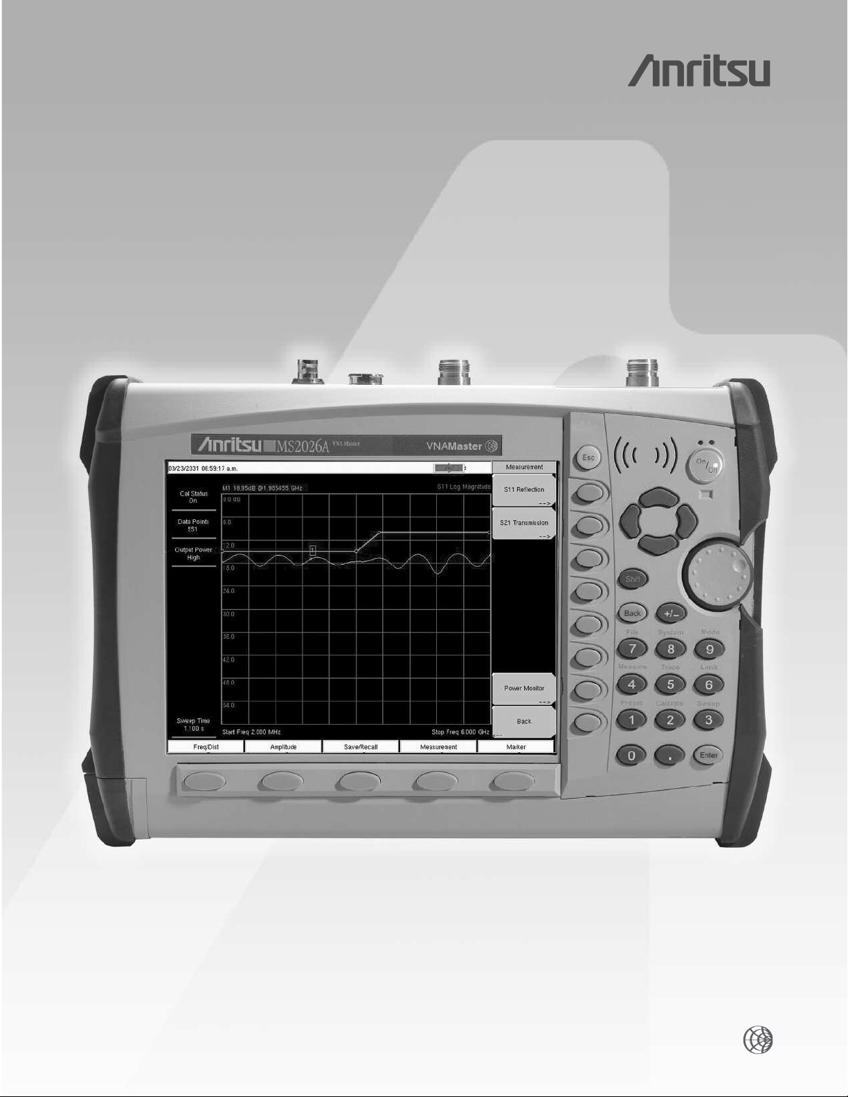
VNAMaster
MS2024A/MS2026A
™
VNA Master
2 MHz to 6 GHz
Handheld Vector Network Analyzer from 2 MHz to 6 GHz
Page 2

0.025-0.3 GHz
0
.3-3 GHz
3-6 GHz
Reflection Magnitude Uncertainty (S21=0)
10
1
0.1
-
60 -50 -40 -30 -20
-
10 0
l
S11l (dB)
Estimated Uncertainty (dB)
0.025-0.3 GHz
0
.3-3 GHz
3-6 GHz
Reflection Phase Uncertainty (S21=0)
100
10
1
-30 -25 -20 -15 -10
-5 0
l
S11l (dB)
Estimated Uncertainty (deg)
Transmission Magnitude Uncertainty (S11=0)
10
1
0
.1
-
60 -50 -40 -30 -20
-10 0
l
S
21
l
(dB)
Estimated Uncertainty (dB)
0
.025-0.3 GHz
0.3-3 GHz
3-6 GHz
T
ransmission Phase Uncertainty (S11=0)
1
00
10
1
-60 -50 -40 -30 -20
-
10 0
l
S21l (dB)
Estimated Uncertainty (deg)
0.025-0.3 GHz
0
.3-3 GHz
3-6 GHz
Introduction
VNA Master MS2024A/MS2026A are the most ultra-portable
VNAs on the market. They are designed to make accurate
vector corrected 1-Port and 1-path 2-Port magnitude and
phase measurements from 2 MHz to 4 GHz (MS2024A) and
2 MHz to 6 GHz (MS2026A). VNA Master’s light weight
6.4 lbs) and three hour battery life time provide you with
(
he flexibility needed to make VNA measurements anywhere.
t
Performance Specification
Frequency
Frequency Range: 2 to 4000 MHz (MS2024A)
Frequency Accuracy: 25 ppm
Frequency Resolution➀: 10 kHz
Data Points: Low, Medium, High (137/275/551)
nterference Immunity
I
On-Channel: +17 dBm
On-Frequency: +10 dBm (RF Out), +30 dBc RF In
1-Port Power:
High: 0 dBm (typical)
2-Port Power:
High: 0 dBm (typical)
Low: –35 dBm (typical)
Corrected Directivity➂: 42 dB (2 MHz to 6 GHz)
1-Port Accuracy➂: = <0.8 + |20 log(1 ±10
System Dynamic Range:
80 dB, 2 MHz to 3 GHz
70 dB, >3 GHz to 5.5 GHz
65 dB, >5.5 GHz to 6 GHz
Return Loss
Range: 0 to 60 dB
Resolution: 0.01 dB
VSWR
Range: 1 to 65
Resolution: 0.01
Cable Loss
Range: 0 to 30 dB
Resolution: 0.01 dB
1-Port Phase
Range: –180° to +180°
Resolution: 0.01°
Smith Chart
Resolution: 0.01
2-Port Gain
Range: –120 to 100 dB
Resolution: 0.01 dB
2-Port Phase
Range: –180
Resolution: 0.01°
Distance-to-Fault (DTF)
Fault Resolution (meters): (1.5 x 10⁸x vp)/∆F vp is the propagation
Horizontal Range (meters): 0 to (data points-1) x Fault Resolution
tical Range
er
V
n Loss):
(Retur
tical Range (VSWR):
er
V
RF Power Monitor (Option 5):
Display Range: –80 to +80 dBm (10 pW to 100 kW)
Detector Range: –40 to +20 dBm (100 nW to 100 mW)
fset Range:
Of
Resolution: 0.1 dB or 0.1 W
Accuracy: ±
➁
2 to 6000 MHz (MS2026A)
:
-E
∆
/20
)| dB, typical
E∆ = Directivity – Measured Return Loss
°
to +180
°
constant and ∆F is F2-F1 in Hz
to a maximum of 1500m (4921 ft)
e datapoints = 137/275/551
wher
0 to 60 dB
1 to 65
0 to +60 dB
1 dB maximum for >–40 dBm
using 560-7N50B
Bias T (Option 10):
Voltage/Current: +12 V, 250 or 500 mA steady state
+15 V, 250 or 500 mA steady state
+18 V, 350 mA steady state
+21 V, 300 mA steady state
+24 V, 250 mA steady state
GPS Receiver (Option 31)
GPS Location Indicator
Latitude, Longitude, Altitude and UTC on Display
General Specifications
Languages
Built-in English, Spanish, Italian, French, German, Japanese, Korean,
and Chinese. Can also customize two additional languages using
Master Software Tools.
Memory
Internal memory provides for the storage and recall of more than
1000 traces and setups. The contents of the internal memory can
be copied to and from a removable Compact Flash Card.
Markers
6 markers (Delta marker, peak search, valley search) and Marker Table.
Traces
View Trace, Memory, Trace-Memory, Trace + Memory, Trace and Memory
Limit Lines
Upper and Lower Limit. Each upper and lower limit can consist of
between one and forty segments.
Display
Bright daylight viewable color TFT LCD, Full SVGA, 8.4 in.
Interface Connectors
Type N female RF Out Port and RF In Port (50Ω)
5-pin Mini-B USB 2.0 for data transfer to a PC
RJ45 Connector for Ethernet 10/100 Base-T
2.5 mm 3-wire headset connector
Remote Programmability Commands
Not available
Power Supply
External DC Input, +12 V, 5A max
ESD Damage Level
10 kV
Maximum Input (Damage Level)
Test Port, Type N: +22 dBm
RF Detector: +20 dBm
Impedance
50Ω
Dimensions
12 x 8 x 3 in. (305 x 203 x 76 mm)
Weight
<6.4 lbs (2.9 kg)
Environment
MIL-PRF-2800F Class 2
C, humidity 85% or less
°
C to 55
°
Operating:
Storage:
Altitude:
Safety
Confor
ms to EN 61010-1 for Class 1 portable equipment
Electr
omagnetic Compatiblity
Meets European Community requirements for CE marking
➀ If display resolution (Span / (DataPoints-1)) is less than 150 kHz, then frequency resolution only
applies to measurements with RF Immunity set to Normal.
➁ On Channel Interference Immunity is specified at >1.0 MHz of the carrier frequency.
On-Frequency Interference Immunity is specified to within ±10 kHz of the carrier frequency.
➂ All accuracy and dir
➃ For data transfer only, remote programmability commands not available.
ectivity specifications apply only when using Anritsu’
–10
C
°
C to 71
°
–51
4600 meters, operating and non-operating
ecision components.
s pr
Page 3

Performance Specifications
0.025-0.3 GHz
0
.3-3 GHz
3-6 GHz
Reflection Magnitude Uncertainty (S21=0)
10
1
0.1
-
60 -50 -40 -30 -20
-
10 0
l
S11l (dB)
Estimated Uncertainty (dB)
0.025-0.3 GHz
0
.3-3 GHz
3-6 GHz
Reflection Phase Uncertainty (S21=0)
100
10
1
-30 -25 -20 -15 -10
-5 0
l
S11l (dB)
Estimated Uncertainty (deg)
Transmission Magnitude Uncertainty (S11=0)
10
1
0
.1
-
60 -50 -40 -30 -20
-10 0
l
S
21
l
(dB)
Estimated Uncertainty (dB)
0
.025-0.3 GHz
0.3-3 GHz
3-6 GHz
T
ransmission Phase Uncertainty (S11=0)
1
00
10
1
-60 -50 -40 -30 -20
-
10 0
l
S21l (dB)
Estimated Uncertainty (deg)
0.025-0.3 GHz
0
.3-3 GHz
3-6 GHz
he following graphs provide measurement uncertainty at 23°C after vector correction for the standard N connector type.
T
The errors are worse-case contributions of residual directivity, source match, frequency response, network analyzer dynamic range,
and connector repeatability. For the 1-path 2-port measurements, transmission tracking, crosstalk and physical load match terms
were added. Calibration components OSLN50-1 were used.
Power Monitor - Detectors
Model Frequency Range Impedance Return Loss Input Connector Frequency Response
5400-71N50
5400-71N75
560-7A50
560-7N50B
560-7S50B
560-7S50-2
560-7K50
A50
560-7V
0.001 to 3 GHz
0.001 to 3 GHz
0.01 to 18 GHz
0.01 to 20 GHz
0.01 to 20 GHz
0.01 to 26.5 GHz
0.01 to 40 GHz
0.01 to 50 GHz
50
Ω
75
Ω
50
Ω
50
Ω
50
Ω
50
Ω
50
Ω
50
Ω
26 dB N(m)
26 dB, <2 GHz
<3 GHz
20 dB,
15 dB, <0.04 GHz
22 dB, <8 GHz
17 dB, <18 GHz
15 dB, <0.04 GHz
22 dB, <8 GHz
17 dB, <18 GHz
14 dB, <20 GHz
15 dB, <0.04 GHz
22 dB, <8 GHz
17 dB, <18 GHz
14 dB, <20 GHz
15 dB, <0.04 GHz
22 dB, <8 GHz
17 dB, <18 GHz
14 dB, <26.5 GHz
12 dB, <0.04 GHz
22 dB, <8 GHz
17 dB, <18 GHz
15 dB, <26.5 GHz
14 dB, <32 GHz
13 dB, <40 GHz
12 dB, <0.04 GHz
19 dB, <20 GHz
15 dB, <40 GHz
10 dB, <50 GHz
N(m)
GPC-7 ±0.5 dB, <18 GHz
N(m)
WSMA(m)
WSMA(m)
K(m)
V(m)
±0.2 dB, <1 GHz
±0.3 dB, <3 GHz
0.2 dB, <1 GHz
±
±0.5 dB, <3 GHz
±0.5 dB, <18 GHz
1.25 dB, <20 GHz
±
±0.5 dB, <18 GHz
±1.25 dB, <20 GHz
0.5 dB, <18 GHz
±
1.25 dB, <26.5 GHz
±
±0.5 dB, <18 GHz
1.25 dB, <26.5 GHz
±
±2.2 dB, <32 GHz
±2.5 dB, <40 GHz
0.8 dB, <20 GHz
±
±2.5 dB, <40 GHz
3.0 dB, <50 GHz
±
Page 4

Ordering Information
VNAMaster
Models
S2024A VNA Master, 2 MHz to 4 GHz
M
S2026A VNA Master, 2 MHz to 6 GHz
M
ptions
O
MS2020/5 Power Monitor (requires external detector)
MS2020/10 Built-in Variable Bias-Tee
MS2020/31 GPS Receiver (including GPS antenna)
Standard Accessories Include:
10580-00122 MS2024A/MS2026A User’s Guide
61382 Soft Carrying Case
64343 Tilt Bail
2300-498 Master Software Tools CD ROM
633-44 Rechargeable battery, Li-Ion
40-168 AC – DC adapter
806-141 Automotive cigarette lighter/12 Volt DC adapter
2000-1360 USB A-mini B cable, 6 ft (1.83 m)
2000-1371 Ethernet cable, 7 ft (2.13 m)
2000-1358 Compact Flash Card (64 MB)
Optional Accessories:
OSLN50-1 Precision N(m) Open/Short/Load, 42 dB, 6 GHz
OSLNF50-1 Precision N(f) Open/Short/Load, 42 dB, 6 GHz
22N50 Precision N(m) Short/Open, 18 GHz
22NF50 Precision N(f) Short/Open, 18 GHz
SM/PL-1 Precision N(m) Load, 42 dB, 6.0 GHz
SM/PLNF-1 Precision N(f) Load, 42 dB, 6.0 GHz
2000-767 Precision Open/Short/Load, 7/16(m), 4.0 GHz
2000-768 Precision Open/Short/Load, 7/16(f), 4.0 GHz
1N50C Limiter, N(m) to N(f), 50
42N50-20 Attenuator, 20 dB, 5W, DC to 18 GHz, N(m)-N(f)
42N50A-30 Attenuator, 30 dB, 50 W, DC to 18 GHz, N(m)-N(f)
2000-1410 Magnet Mount GPS Antenna with 15 ft
Test Port Cables Armored
15NN50-1.5C 1.5 meters, N(m)-N(m), 6 GHz, 50Ω
15NN50-3.0C 3.0 meters, N(m)-N(m), 6 GHz, 50Ω
15NN50-5.0C 5.0 meters, N(m)-N(m), 6 GHz, 50Ω
15NNF50-1.5C 1.5 meters, N(m)-N(f), 6 GHz, 50Ω
15NNF50-3.0C 3.0 meters, N(m)-N(f), 6 GHz, 50Ω
15NNF50-5.0C 5.0 meters, N(m)-N(f), 6 GHz, 50Ω
15ND50-1.5C 5.0 meters, N(m)-7/16 DIN(m), 6 GHz, 50Ω
15NDF50-1.5C 5.0 meters, N(m)-7/16 DIN(f), 6 GHz, 50Ω
ecision Adapters
Pr
34NN50A N(m)-N(m), DC to 18 GHz, 50Ω
34NFNF50 N(f)-N(f), DC to 18 GHz, 50Ω
Adapters
1091-26 N(m)-SMA(m), DC to 18 GHz, 50Ω
1091-27 N(m)-SMA(f), DC to 18 GHz, 50Ω
1091-80 N(f)-SMA(m), DC to 18 GHz, 50Ω
1091-81 N(f)-SMA(f), DC to 18 GHz, 50Ω
1091-172 N(m)-BNC(f), DC to 1.3 GHz, 50Ω
One Year Warranty
Ω, 0.01 to 50 GHz
(4.6 m) cable
Band Pass Filters
1030-109 836.5 MHz Ctr Freq, 25.8 MHz BW,
1030-110 897.5 MHz Ctr Freq, 35 MHz BW,
1030-111 1.88 GHz Ctr Freq, 63.1 MHz BW,
1030-112 2.442 GHz Ctr Freq, 85.1 MHz BW,
Detector Extender Cables
800-109 7.6 m (25 ft)
800-110 15.2 m (50 ft)
800-111 30.5 m (100 ft)
800-112 61.0 m (200 ft)
760-235 Hard Transit Case
10580-00122 MS2024A/MS2026A User’s Guide
61382 Soft Carrying Case
64343 Tilt Bail
2300-498 Master Software Tools CD ROM
633-44 Rechargeable battery, Li-Ion
40-168 AC – DC adapter
806-141 Automotive cigarette lighter/12 Volt DC adapter
2000-1358 Compact Flash Card (64 MB)
2000-1360 USB A-mini B cable, 6 ft (1.83 m)
2000-1371 Ethernet cable, 7 ft (2.13 m)
2000-1374 Dual Battery Charger
N(m)-SMA(f), 50Ω
N(m)-SMA(f), 50Ω
N(m)-SMA(f), 50Ω
N(m)-SMA(f), 50Ω
Literature:
s Guide
10580-00122
10580-00123
11410-00369
11410-00274
11410-00214
MS2024A/MS2026A User
MS2024A/MS2026A Pr
MS2024A/MS2026A Br
ower Mounted Amplifiers Application Note
T
Reflection Measur
’
ogrammng Manual
e
ochur
ement Application Note
510-90 7/16 DIN(f)-N(m), DC to 7.5 GHz, 50Ω
510-91 7/16 DIN(f)-N(f), DC to 7.5 GHz, 50Ω
510-92 7/16 DIN(m)-N(m), DC to 7.5 GHz, 50Ω
510-93 7/16 DIN(m)-N(f), DC to 7.5 GHz, 50Ω
510-96 7/16 DIN(m)-7/16 DIN(m), DC to 7.5 GHz, 50Ω
510-97 7/16 DIN(f)-7/16 DIN(f), DC to 7.5 GHz, 50Ω
510-102 N(m)-N(m) 90º right angle, DC to 11 GHz, 50Ω
SALES CENTERS:
United States (800) ANRITSU Europe 44 (0) 1582-433433 Microwave Measurement Division
Canada (800) ANRITSU
South America 55 (21) 2527-6922 Asia-Pacific (852) 2301-4980 http://www.us.anritsu.com
11410-00372, Rev. B
vis Drive, Morgan Hill, CA 95037-2809
Japan 81 (46) 223-1111
Anritsu March 2006. All trademarks are registered trademarks of their respective companies.
©
Data is subject to change without notice. For more recent specifications visit www
490 Jar
.us.anritsu.com.
Discover What’s Possible
®
 Loading...