

Page 1
MPRT
Megger Protective Relay Test System
I
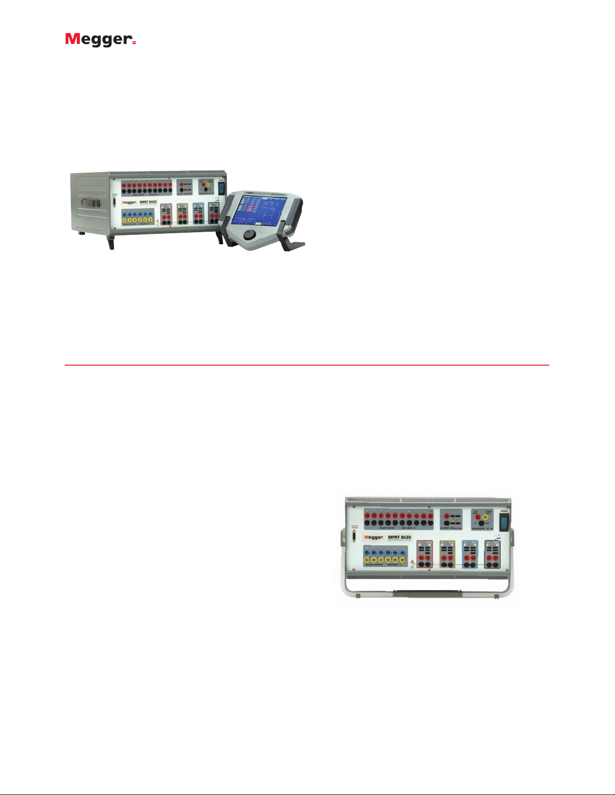
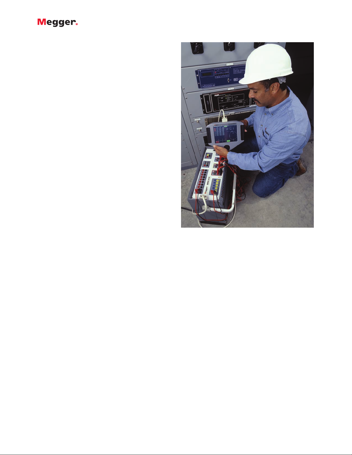
The MPRT System consists of a
‘Power Box’, the TouchView Interface™,
and AVTS Software
I
Unique new TouchView Interface (TVI)
simplifies the manual testing of complex
relays
I
Ultra flexible output design provides
up to four-phase voltage and current
or eight-phase current
I
User specified configuration.
Every system is made to order based
on specific customer needs.
I
Includes fully automated testing capability
using AVTS Software (Version 3.0)
MPRT
Megger Protective Relay Test System
DESCRIPTION
The MPRT System is comprised of:
• The ‘Power Box’
• The TouchView Interface (TVI)
• AVTS Software
The ‘Power Box’ is the heart of the system. It employs a
variety of new features including unique Voltage and
Current Generator (VI-Gen) components which have been
combined into one amplifier package. Using multiple
VI-Gens provides the flexibility to deliver four voltages (or
two three-phase open delta voltages) and four currents or
combinations up to eight current channel capability. The
MPRT ‘Power Box’ also incorporates three communication
ports, a new Constant Power Output (CPO) capability and
every one is made-to-order based on each customer’s
individual testing requirements.
The TouchView Interface (TVI) device and AVTS Basic
Software form the brains of the system. The TVI, with its
large full color touch screen allows the user to perform
manual and semi-automatic testing quickly and easily,
using built-in, preset test routines for most popular relays.
Fully automatic testing can also be performed using AVTS
Basic Software which comes with the MPRT System.
APPLICATIONS
MPRT is specifically designed to perform routine testing of
protective relays used in the operation of electric utilities,
power plants and heavy industrials. Other applications
include use in government facilities, harbor and airport
installations, large building complexes and by testing
service companies who are increasingly interested in a
highly flexible, easy-to-use relay test instruments that can
help them improve their job efficiency.
MPRT SYSTEM COMPONENTS
The ‘POWER BOX’
The ‘Power Box’ is ultra flexible, rugged, lightweight and
feature packed. The unique features include:
NEW Constant Power Output (CPO) Capability –
Produces improved power output sustainable through the
entire “power curve” of a test. With a CPO of 200 VA per
current channel and 150 VA per voltage channel it has the
flexibility to test any relay.
Unique VI-Gen Internal Design – The Voltage and
Current Generator (VI-Gen) components have been
combined into one amplifier package. Using multiple
VI-Gens the system has the flexibility to deliver four
voltages (or two three-phase open delta voltages) and four
currents or eight currents for testing multi-phase
differential relays.
Built-in Transducer Testing Capability – Eliminates the
need for additional testing equipment or software. The
MPRT incorporates high accuracy amplifiers, a special
transducer DC input and test algorithms to test transducers
easily and effectively.
Shown without optional adjustable carry handle.
Shown with optional adjustable carry handle.
Page 2
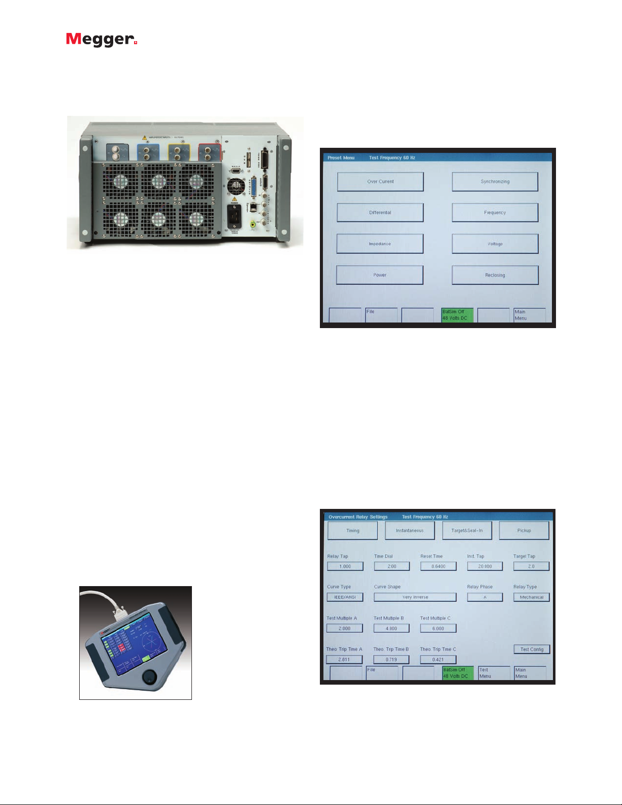
Here’s how easy it is
From the Preset Menu Screen, shown below, the user
simply selects the type of relay to be tested. Built-in test
files are for a wide variety of protective relays, including
Overcurrent, Differential, etc., see following figure.
MPRT
Megger Protective Relay Test System
2
Includes Three Communication Ports – More built-in
flexibility with a protocol choice of IEEE488, RS232 or
Ethernet for high-speed download capability and upgrades
via the internet.
User Specified Configuration – Every system is made to
order based on each customer’s testing requirements and
budget, with an easy and flexible upgrade path.
Output Capabilities for Worldwide Use – Even more
built-in flexibility allows the user to choose from:
I
VI-Gen amplifiers rated at 30A @ 200 VA and
convertible amplifiers rated at 300V or 5A @ 150 VA.
I
VI-Gen amplifiers rated at 15A @ 200 VA and
convertible amplifiers rated at 150V or 5A @ 150 VA.
THE TOUCHVIEW INTERFACE (TVI)
Finally...an easier way to perform manual and semiautomatic relay testing. It’s all done via a unique hand
held controller called the TouchView Interface (TVI). The
most significant feature of the TVI is its ability to provide
the user with a very simple way to manually test even the
most complex relays manufactured today.
Manual operation is simplified through the use of a
built-in computer operating system and the TouchView
Interface, with a large color LCD touch-screen. The TVI
eliminates the need for a computer when testing virtually
all types of relays. Menu screens and function buttons are
provided to quickly and easily select the desired test
function.
Preset Relay Menu Screen
Overcurrent Relay Settings Screen
As an example, touch the ‘Over Current’ button. An
Overcurrent Test Menu Screen, shown below, will be
displayed showing all necessary functions needed to test
that particular type of relay. Next, the user inputs the relay
setting values that will be used to conduct the tests, such
as Relay Tap value and Time Dial value. These values are
used when conducting the pickup and timing tests.
To make it even better, the TVI has both IEEE and IEC
time curve algorithms built-in. By entering the appropriate
values in the setting screen, when the timing test is
conducted, the test results will be automatically compared
to the theoretical values from the time curve that was
selected.
MPRT TouchView Interface
TM
Back view of MPRT.
Page 3
MPRT
Megger Protective Relay Test System
3
As shown in the Overcurrent Settings screen, the IEEE Very
Inverse time curve was selected. If the Test Multiple is
changed, the appropriate theoretical trip time will change
automatically.
The TVI also has the ability to do even more complex tests
and calculations. For example, the MPRT with three
Voltage/Current Modules, can test single-phase, three-phase
open delta, and three-phase wye impedance relays using
the Impedance relay test screen. The user simply selects
different testing applications from a menu screen. For
instance, the Reach Test Settings Screen for an impedance
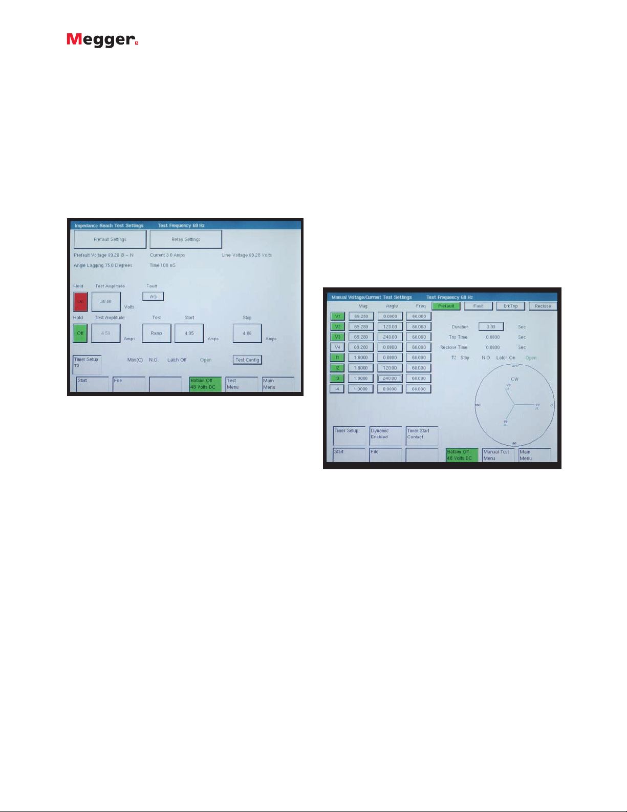
relay has been selected as shown below.
Impedance Reach Test Settings Screen
It should be noted that not only does the display screen
show values of voltage, current and phase angle, but it
also displays the current value where the relay should pick
up, (different formulas for calculating OHMS are selectable
using the touch-screen to select phase to phase or phase
to ground faults). The user can select ramp current and
hold fault voltage on ramp voltage and hold fault current.
The impedance test screen provides a pre-fault condition
for those relays that require a pre-fault load prior to
applying the fault. The test automatically determines values
like reach, maximum angle of torque, and timing.
Finally, for testing multi-zone relays, the user can select
the Pulse-Ramp method to determine operating points
without needing to defeat the other zone timers. Test
results can be saved to the internal memory for later
download and review.
Also easily test relays not on the Preset Menu
Other types of relays or devices not specifically listed in
the Preset Menu Screen can be tested using one of the
Manual Test screens.
Manual Voltage/Current Test Screen
For example, negative sequence under/over voltage,
reverse phase, phase sequence, and current balance relays
may be tested using the Voltage/Current manual test screen.
In addition, manual control of up to four voltages and
currents, or up to 8 currents is done using this test screen.
Other devices such as auto-synchronizing, frequency
sensitive devices and transducers also have their own
individual manual test screens. The user manually selects
the parameter(s) to be set or adjusted using the touchscreen and ramp outputs using the control knob. Each test
screen has a dynamic enable capability and will either
automatically step from a prefault, to fault, to breaker trip,
to reclose, or automatically ramp frequency at a
preprogrammed Hz/Sec, or time for a given slip frequency,
depending on which screen is in use. In the Manual AutoSynchronizing Test Screen, the advanced closing time and
closing angle are automatically done in the dynamic mode.
In the Manual Test Screen shown above, the pre-selected
outputs are set. The Green color indicates which output(s)
have been selected. When the test is started by pressing
the Start button, the selected output indicators will change
colors from green to red indicating which outputs are
energized. A vector graph indicates the relative phase
angles of all of the outputs. All of the outputs are metered
and displayed to provide real time verification of all of the
selected outputs.
Even perform manual transducer testing
With the built-in transducer test screen, manually testing
transducers has never been easier. The user simply selects
from a pull-down menu, what type of transducer is being
tested and enters information relative to the transducer’s
inputs and outputs. Upon starting the test, the test set
automatically measures and calculates the % error of the
device.
Page 4
MPRT
Megger Protective Relay Test System
4
From any test screen, the user has access to the Test File
Manager Screen. The user can give the test file/result file
any name up to a maximum of 99 characters. Once saved,
the user can recall the test and execute with the
appropriate settings already set, or recall saved test results
to download into the AVTS database for storage or for
printing.
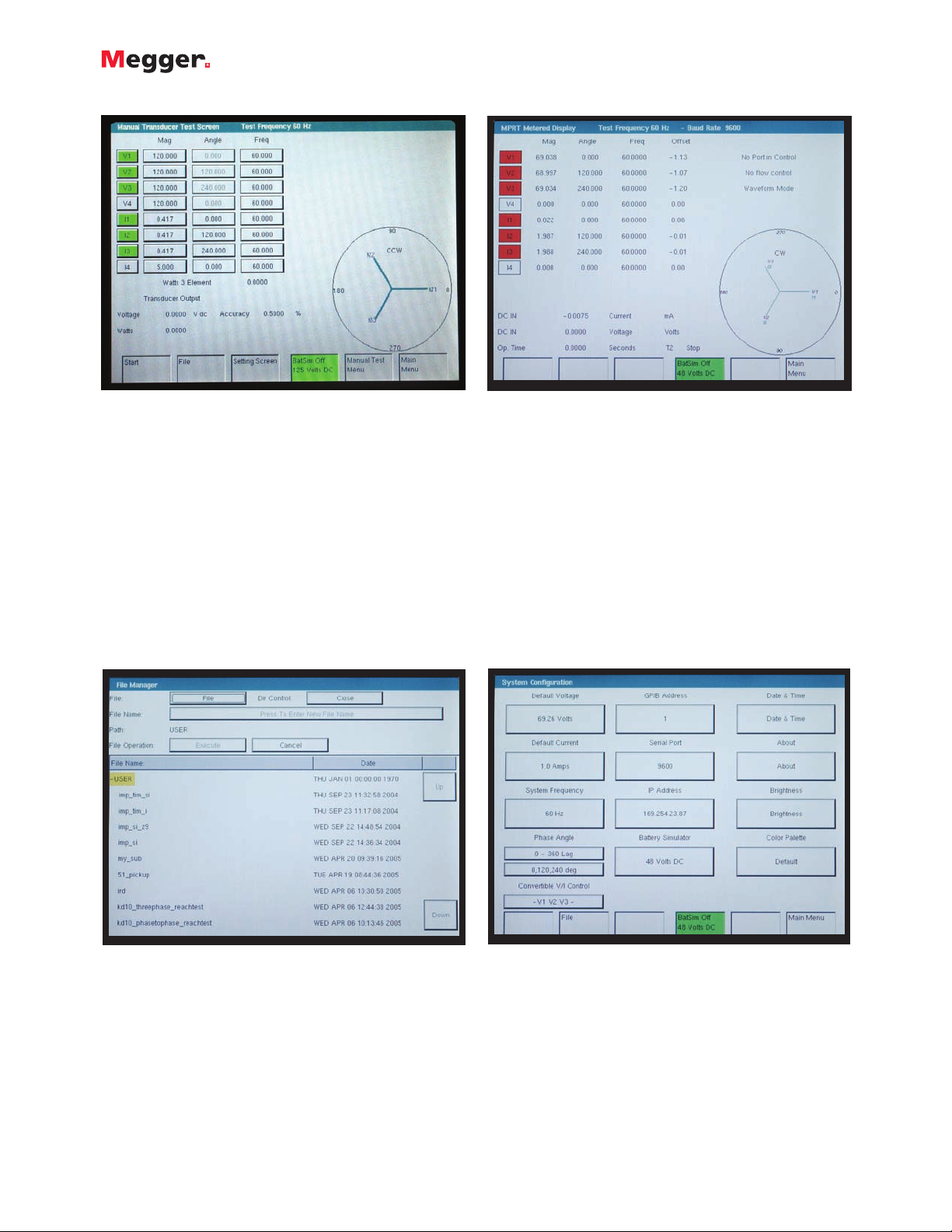
All output values are metered and displayed
When under automatic computer control (with the AVTS
software), the TVI becomes a meter display for all of the
MPRT outputs. The metered values are displayed to
Meter Display Screen
TVI Default Setting Screen
Transducer Test Screen
In the above example, a three-phase, 3 Element Watt
Transducer is being tested. The actual output watts is
calculated based upon the measured values from the
MPRT into the transducer, and the transducer watts
is calculated based upon the measured output
voltage/current from the transducer. A % error is
automatically calculated and displayed. A vector
representation of the voltage and current outputs
is also displayed.
Use the File Manager to organize all test results
The TVI has sufficient internal memory to save hundreds
of test and result files. To manage the tests and results, the
MPRT has a File Manager screen.
File Manager Screen
provide continuous real-time verification of the MPRT
outputs, even when under automatic control.
Output values are displayed with a vector display, which
shows the vector relationship between the output voltage
and currents.
User customized configuration
The user may customize how the unit displays phase
angles (0-360° Lead/Lag or ± 180°), and set default values
of voltages, currents and frequency. The user may also
select a language for prompting the operator. Five
language choices are currently available, English, French,
German, Portuguese and Spanish.
Other default settings include GPIB and IP addresses,
Serial Port settings, Battery Simulator output and screen
background colors.
AVTS SOFTWARE
See page 8 for details regarding AVTS Software.
Page 5
MPRT
Megger Protective Relay Test System
5
FEATURES AND BENEFITS
I
Large Color LCD touch-screen display - The TVI
features an easy to use and read display providing
manual control of the test set, and displays measured
values of voltage, current, along with phase angle and
frequency. Calculated values such as Ohms, Watts, VAR’s
and Power Factor may also be displayed, depending on
the test screen in use. Color contrasts accentuate vital
information. This reduces human error and time in
testing relays.
I
Constant Output Power - The new MPRT employees
new high powered Voltage-Current amplifiers (VI-Gens),
which deliver maximum compliance voltage to the load
constantly during the test. Constant output power in
many cases eliminates the need to parallel current
channels together to test high burden relays.
I
High resolution and accuracy - The TVI has Metered
outputs and a timer to provide extremely high accuracy.
High accuracy extends testing capability to other devices
such as transducers.
I
Internal memory - The TVI provides storage of test
set-up screens and test results. Reduces testing time and
paper work. Saved test results can be downloaded into
the AVTS software database.
I
Steady-State and Dynamic testing capability - The
MPRT provides, either through manual control or
computer control, both steady-state and dynamic testing
of protective relays. This includes programmable
waveforms with dc offset and harmonics.
I
Display screen prompts operator - The TVI features
a display screen that prompts the user with easy to use
function buttons. Single button operation saves time in
testing relays and minimizes human error.
I
Display screen provides five different languages The TVI display screen prompts the user in English,
Spanish, Portuguese, French or German.
I
Output current and voltage sinewaves are generated
digitally - MPRT outputs do not vary with sudden
changes in input voltage or frequency, which increases
test accuracy and reduces testing time.
I
Memory metering - Allows the user to set test currents
and voltages faster. Reduces heating of device under
test.
I
Digital inputs and outputs - MPRT has 10
programmable inputs, and 6 programmable outputs
provide timing and logic operations in real-time with the
output voltage and currents. Binary Inputs can be
programmed, using Boolean logic, for more complex
power system simulations. This provides a low cost,
closed loop, power system simulator.
I
Circuit breaker simulator - MPRT’s binary outputs
provide programmable normally closed and normally
open contacts to simulate circuit breaker operation for
testing reclosing relays. Sequence of operation, timing,
and lockout are easily tested.
I
Performs transient tests - Perform acceptance or
troubleshooting tests by replaying digitally recorded
faults or EMTP/ATP simulations in the IEEE- C37.111,
COMTRADE Standard format.
I
Perform End-to-End tests - Using AVTS software and a
portable GPS satellite receiver, the MPRT performs
satellite-synchronized end-to-end dynamic or transient
tests. Provides precisely synchronized testing of remotely
located complex protection schemes.
I
Wide-ranging output frequency - The output
frequency of the current and voltage channels can be set
for any frequency from dc to 1 kHz. Popular test
frequencies such as 25, 50, 60 and 100 Hz are easily set
and controlled. Provides ultra-flexability to save time
and lower costs.
I
RS-232 serial port - The RS-232 port provides a
computer interface to perform automatic testing.
I
Ethernet port - The Ethernet port provides a highspeed computer interface. This can be used to quickly
download transient waveform data and update test set
firmware via internet.
I
IEEE-488GPIB - The IEEE-488 is an OEM preferred
interface for control of the unit. This interface is
preferred, when using the unit with other IEEE-488
devices. It can also provide high speed downloading of
transient data.
Page 6
MPRT
Megger Protective Relay Test System
6
I
Universal input voltage - Operating from 90 to 264
Vac, 50/60 Hz, the MPRT can use virtually any standard
source in the world.
I
Battery simulator - MPRT’s battery simulator provides
dc output voltages of 24, 48, 125 and 250 Volts.
Eliminates needing a separate dc source for providing
logic voltage for microprocessor-based relays.
I
Immediate error indication - Audible and visual
alarms indicate when amplitude or waveforms of the
outputs are in error.
I
Modular design - Output modules plug-in and slide
out easily for system re-configuration and maintenance.
I
Ancillary Interface - Provides interface to other MPRT
units.
I
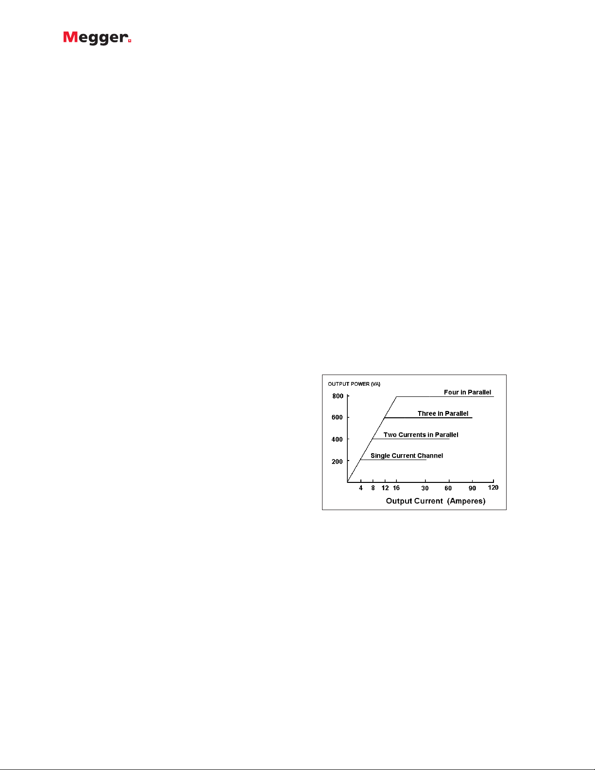
MPRT Model 8430 - Provides up to 300 Volts rms. at
150 VA and 30 Amps rms. at 200 VA per phase. Ample
voltage for testing high instantaneous overvoltage relays.
The current amplifier has high compliance voltage at
low currents for testing ground overcurrent relays. When
configured with four channels, the current amplifiers can
be paralleled to provide a maximum of 120 Amperes at
800 VA, for testing instantaneous overcurrent relays.
With high VA output ratings, the unit can be used for
testing a panel of relays.
I
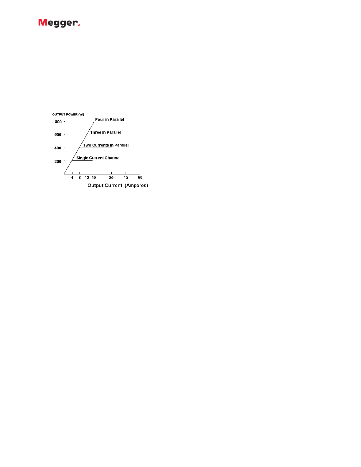
MPRT Model 8415 - Provides up to 150 Volts rms. at
150 VA and 15 Amps rms. at 200 VA per phase. This
lower cost unit is ideal for testing relays used with 1
Amp secondary CT’s. The current amplifier has high
compliance voltage at low currents for testing ground
overcurrent relays. When configured with four channels,
the current amplifiers can be paralleled to provide a
maximum of 60 Amperes at 800 VA, for testing
instantaneous overcurrent relays. With high VA output
ratings, the unit can be used for testing a panel of
relays.
SPECIFICATIONS
Input Power
100 to 240 Volts, ±10%, AC, 1Ø, 50/60 Hz, 2100 VA.
Outputs
All outputs are independent from sudden changes in line voltage
and frequency. This provides stable outputs not affected by
sudden changes in the source. All outputs are regulated so
changes in load impedance do not affect the output. Each output
module consists of one current amplifier, and a voltage amplifier.
The voltage amplifier may be converted to a current source.
Therefore, one amplifier module may be used to test current
differential relays, including harmonic restraint.
Output Current
The following specifications cover both Model 8430 and Model
8415 modules. Outputs are rated with the following:
Model 8430
Per phase:
Output Current Power Max V
4 Amperes 200 VA 50.0 Vrms
7.5 Amperes 200 VA 26.7 Vrms
15 Amperes 200 VA 13.4 Vrms
30 Amperes 200 VA 6.67 Vrms
DC 200 Watts
With two currents in parallel:
Output Current Power Max V
8 Amperes 400 VA 50.0 Vrms
15Amperes 400 VA 26.7 Vrms
30 Amperes 400 VA 13.4 Vrms
60 Amperes 400 VA 6.67 Vrms
With three currents in parallel:
Output Current Power Max V
12 Amperes 600 VA 50.0 Vrms
22.5Amperes 600 VA 26.7 Vrms
45 Amperes 600 VA 13.4 Vrms
90 Amperes 600 VA 6.67 Vrms
With four currents in parallel:
Output Current Power Max V
16 Amperes 800 VA 50.0 Vrms
30 Amperes 800 VA 26.7 Vrms
60 Amperes 800 VA 13.4 Vrms
120 Amperes 800 VA 6.67 Vrms
Power Curve for Model 8430
With two currents in series, the compliance voltage doubles to
provide 4.0 Amperes at 100 Volts.
Model 8415
Per phase:
Output Current Power Max V
4 Amperes 200 VA 50.0 Vrms
7.5 Amperes 200 VA 26.7 Vrms
15 Amperes 200 VA 13.4 Vrms
DC 200 Watts
With two currents in parallel:
Output Current Power Max V
8 Amperes 400 VA 50 Vrms
15 Amperes 400 VA 26.7 Vrms
30 Amperes 400 VA 13.4 Vrms
Page 7
MPRT
Megger Protective Relay Test System
7
With three currents in parallel:
Output Current Power Max V
12 Amperes 600 VA 50 Vrms
22.5Amperes 600 VA 26.7 Vrms
45 Amperes 600 VA 13.4 Vrms
With four currents in parallel:
Output Current Power Max V
16 Amperes 800 VA 50 Vrms
30 Amperes 800 VA 26.7 Vrms
60 Amperes 800 VA 13.4 Vrms
Battery Simulator
The battery simulator provides the following DC output:
24, 48, 125 or 250 Volts at 60 Watts. Voltage output is controlled
via the Touch-View Interface, or through AVTS software.
Metering
Measured output quantities such as AC Amperes, AC Volts, DC
Volts or DC Amperes, and Time may be simultaneously displayed
on the large, variable contrast, color LCD touch screen. The
memory feature of the metering provides fast and accurate preset
of test values. The AC and DC outputs display the approximate
voltage/current output prior to initiation of the outputs. This
provides a fast, easy method for preset of outputs. Other values
that may be displayed, depending on which test screen is in view,
are phase angle, frequency, Ohms, Watts, VARS and Power Factor.
All Accuracies stated are from 10 to 100% of the range at 50/60 Hz.
AC Voltage Amplitude
Accuracy: ±0.05% typical, 0.1% guaranteed.
Resolution: .0001/.001/.01
Measurements: True RMS
AC Current Amplitude
Accuracy: ±0.05% typical, 0.1% or ±20 mA, which ever is greater,
guaranteed.
Resolution: .0001/.001/.01
Measurements: True RMS
DC Voltage Amplitude
Accuracy: ±0.1% typical, 0.25 % guaranteed.
Resolution: .0001/.001/.01
Measurements: True RMS
DC Current Amplitude
Accuracy: ±0.1% typical, 0.25 % or ±20 mA, which ever is greater,
guaranteed.
Resolution: .0001/.001/.01
Measurements: True RMS
Convertible Source in AC Current Mode
Accuracy: ±0.05% typical, 0.1 % or ±12.5 mA,
which ever is greater, guaranteed.
Resolution: .0001
Measurements: True RMS
Phase Angle
Ranges 0.01 to 359.99 degrees, Counter Clock Wise,
or Clock Wise rotation, or ±0.01 to ±180.00 degrees
Accuracy: ± 0.02° typical
± 0.25° at 50/60 Hz max
Frequency:
The output modules provide a variable frequency output with the
following ranges and accuracy.
Ranges
DC
0.001 to 1000.000 Hz
Output amplifiers can provide transient signals with a range of
DC to 10 kHz for transient playback.
Resolution: .001 Hz
Frequency Accuracy:
2.5 ppm typical
25 ppm 0° to 50° C, at 50/60 Hz
Total Harmonic Distortion:
Less than 0.1% typical,
2% maximum at 50/60 Hz.
Power Curve for Model 8415
With two currents in series, the compliance voltage doubles to
provide 4.0 Amperes at 100 Volts.
AC Voltage Output
The following specifications cover both the Model 8430 and 8415
modules. Outputs are rated with the following Ranges:
Model 8430
Per phase:
Output Volts Power Max I
30 Volts 150 VA 5 Amps
150 Volts 150 VA 1 Amp
300 Volts 150 VA 0.5 A
DC 150 Watts
With two voltages in series:
Output Volts Power Max I
60 Volts 300 VA 5 Amps
300 Volts 300 VA 1 A
600 Volts 300 VA 0.5 A
With three converted sources in parallel:
Output Current Power Max V
15Amperes 450 VA 30 Vrms
Model 8415
Per phase:
Output Volts Power Max I
30 Volts 150 VA 5 Amps
150 Volts 150 VA 1 Amp
DC 150 Watts
With two voltages in series:
Output Volts Power Max I
60 Volts 300 VA 5 Amps
300 Volts 300 VA 1 A
With three converted sources in parallel:
Output Current Power Max V
15Amperes 450 VA 30 Vrms
Page 8

MPRT
Megger Protective Relay Test System
8
Power
The Watts displayed is the calculated value based on the displayed
formula. Nine different formulas are available.
Range: 0 to 15 kW
Accuracy: ± 0.525 % of VA ±1 least significant digit
The DC IN input terminals
Range:
0 to ±10 V DC
0 to ± 20 mA DC
Accuracy: ±0.02% Typical
±0.05% Max
Resolution: .0001/.001
Measurements: Average
Timer-Monitor
The Timer-Monitor (Binary Inputs) are designed to monitor and
time-tag inputs, as a sequence of events recorder. In addition, the
binary input controls enable the user to perform logic AND/OR
functions on the inputs, and conditionally control the binary
output relays to simulate circuit breaker, trip, reclose and carrier
control operation in real-time. The Timer function displays in
Seconds or Cycles, with the following range and resolution:
Seconds: 0.0001 to 99999.9
(Auto Ranging)
Cycles: 0.01 to 99999.9
(Auto Ranging)
Accuracy: ±0.001% of reading, typical. ±2 least significant digit,
±0.005% of reading from 0 to 50° C maximum.
Binary Inputs- Start/Stop/Monitor Gates
10 identical, independent, galvanically isolated, Start/Stop or
Monitor circuits are provided. To monitor operation of relay
contacts or trip SCR, a continuity light is provided for each input
gate. Upon sensing continuity the lamp will glow and a tone
generator will sound. In addition to serving as Timer/Monitor
inputs, the Binary Inputs may be programmed to trigger binary
output sequence(s). Binary Inputs can also be programmed using
Boolean logic for more complex power system simulations.
Input Rating: up to 300 V AC/DC
Binary Output Relays
6 identical, independent, galvanically isolated, output relay
contacts accurately simulate relay or power system inputs to
completely test relays removed from the power system. Binary
outputs simulate normally open / normally closed contacts for
testing breaker failure schemes. Outputs can be configured to
change state based on binary input logic (Boolean logic is
available for more complex simulations), or a specified time delay
after a logic input condition.
Contact Rating: Up to 400 Volts peak, AC/DC, 1 Amp
continuous, 3 Amps Max.
Waveform Generation
Each output channel can generate a variety of output waveforms
such as: DC; sinewave; sinewave with percent harmonics at
various phase angles; half waves; square waves with variable duty
cycles; exponential decays; periodic transient waveforms from
digital fault recorders, relays with waveform recording capability
or EMTP/ATP programs, which conform to the IEEE C37.111
COMTRADE standard format. In addition, each output channel has
input BNC connector for amplification of external analog signals.
Waveform Storage
Each output channel can store waveforms for playback on
command. End-to-end playback of stored waveforms is possible,
when triggered externally by a GPS receiver. Each channel can
store up to 256,000 samples.
Protection
Voltage outputs are protected from short circuits and prolonged
overloads. Current outputs are protected against open circuits and
overloads.
Ancillary Interfaces
On the back panel of the MPRT are the RS-232, Ethernet, IEEE488 GPIB, Trigger In, Trigger Out, Clock In, and Clock Out.
Temperature Range
Operating: 32 to 122° F (0 to 50° C)
Storage: -13 to 158° F (-25 to 70° C)
Relative Humidity: 5 - 90% RH, Non-condensing
Dimensions
Unit Enclosure
17.2 W x 8.75 H x 18.5 D* in. (430 W x 218 H x 463 D mm)
*Includes 2.5” depth of floor stand-offs
Weight
Weight varies depending on the number of output modules in the
system. The weights shown below are for a complete three-phase
test system.
Model 8415: Model 8430:
41.8 lb. (18.9 kg) 41.8 lb. (18.9 kg)
Safety, EMC, RFI and ESD Conformance
IEC 61010-1, Amendments 1 and 2, EN 50081-2, EN 50082-2,
EN 61000-3-2, 61000-3-3, IEC 61000-4-2/3/4/5/6/8/11.
Shock, Vibration and Temperature
To simulate the worst field conditions the unit was tested in
accordance with Military Standard MIL-STD-810 for temperature,
humidity, shock, and vibration.
Enclosure and Transit Cases
The unit comes mounted in a rugged enclosure for field
portability. There are three versions of the enclosure. The L
version has carry handles on the sides for easy mobility, and a
carry strap that connects to the chassis. Small fold up feet built
into the bottom of the chassis serve to tilt the face of the unit up
when operating on a bench top. The enclosure has vertical standoffs on the back that allows the unit to be operated vertically off
the floor. The H version is the same as the L with an additional
MPRT in optional softsided case.
One-piece hardsided case.
Two-piece hard-sided case.
Page 9

MPRT
Megger Protective Relay Test System
9
extra large adjustable carry handle that can also be used to tilt the
face of the unit up. The H version does not come with a carry
strap. Both units may be carried in the optional soft sided carry
case, Part Number 684011. The soft sided case has approximately
1 inch thick padding, which provides moderate protection against
rain, dust, vibration and shock. For higher level transit protection,
optional custom made hard sided transit cases are available. The
one piece transit case, part number 684019, provides protection
for the MPRT and the Touch View Interface, as well as provides
storage facilities for the power cord, interface cables and test
leads. The case has built-in wheels and a telescoping handle. The
two piece hard sided transit case also has built-in wheels and a
telescoping handle, part number 674002. The two piece hard
sided transit case was specifically designed to reduce the size and
weight for those who use commercial airlines. Therefore, only the
L version will fit in the two piece case (the H version is heavier
by about 2.2 pounds or 1 kg). The larger of the two pieces is
designed to carry the MPRT. The second smaller case has storage
space for the TVI, power cord, interface cables and test leads. The
weight of a 3 channel MPRT unit in the two piece transit case is
approximately 66 pounds or 29.7 kg. The weight of the second
case with test leads will vary depending on the number of test
leads stored. Typically the weight will be about 27 pounds or 12.2
kg. The last version of the unit enclosure is the R version, or rack
mount version. The R version includes rack mounting hardware to
fit a standard 19 inch rack.
AVTS
Advanced Visual Test
Software Version 3.0
DESCRIPTION
AVTS is a Microsoft
®
Windows®98/ME/NT4.0/2000/XP
®
software program designed to manage all aspects of
protective relay testing using the new Megger MPRT or
older PULSAR relay test sets. More flexibility has been
added as well as some new and powerful features.
AVTS 3.0 comes in three different levels:
I
Basic
I
Advanced
I
Professional
Every MPRT unit comes with AVTS Basic.
The Basic version includes Online Vector, Ramp and ClickOn-Fault controls with the ability to import, save and execute
test modules. In addition, the Basic version includes enhanced
Relay Test Wizards, including new wizards not previously
available.
The Advanced version includes the Test Editor, Dynamic
Control, Modbus, One-Touch Test, SS1 Converter, End-toEnd test macros and basic programming Tools for creating
and editing test modules.
The Professional version includes all of the features of
the Basic and Advanced versions plus some new and
powerful features. It includes the DFR Waveform Viewer
and editor, and Waveform Digitizer.
APPLICATIONS
Using the Online Ramp Control, traditional steady-state
tests are easily performed with AVTS by simply applying
test quantities to the device under test and automatically
ramping the current, voltage, phase angle or frequency.
Using either the Online Ramp, Vector or Dynamic Controls,
Dynamic tests can easily be performed. The dynamic test
includes setting a prefault condition and allowing the
software to automatically test/search for the operating
characteristic of the relay by selecting one of several
available methods. Using Test Wizards or Test Modules,
fault types are selected from a pull-down window.
Operating characteristics for virtually any type of relay are
easily defined using Mho circles, Lenticular, Tomato
characteristics, or a combination of lines, line and slope,
time and amplitude, calculated value or theoretical object
(a time-current curve may be scanned into the program
using the digitizer feature in either the Advanced or
Professional versions of AVTS).
The AVTS Test Screen enables the user to view test values
(both theoretical and actual) on one screen. For example,
the figure above shows test values, both theoretical and
actual results, all on one screen.
The chart on the following page provides an easy
reference showing the features of each version of AVTS
Software.
Page 10

10
Online Vector Control
Online Ramp Control
On-Line Click On Fault
RIO File Format
DFR Playback
Fault Calculator
Import, Save, and
Execute Test Modules
Overcurrent Wizard
Over/Under Voltage
Wizard
Distance Wizard
Differential Wizard
Directional Wizard
Transducer Testing
with Touch-View
Interface or AVTS software
Test Editor
Dynamic Control
Basic Programming
Tool
One-Touch Test™
Modbus
SS1 File Converter
Import Aspen Relay
Database
®
End-to-End Test Macro
Waveform Digitizer
DFR Waveform Viewer
and Playback
The Online Vector Control allows the user to have direct control of the Relay Test System. Up to sixteen
vector states may be created and sequenced back through the test system.
Preramp (prefault), Ramp 1 and Ramp 2 are available for use to be played back through the test system.
Automatically Ramp or Pulse Ramp outputs. PulseRamp provides the capability to determine reach points
on multi-zone distance relays without having to defeat the zone timing elements, and provides pre-fault
load conditions for relays that require it. Enable timer control with either ramp. PulseRamp is available
down to the basic level.
The user can define the type of operating characteristic using the AVTS Theoretical Control or Import files
in the RIO file format, then click at a point on the characteristic that they wish to test for, either as a Shot,
a Check Point or using the Search features. If using the Search the test will progress down a line, using
click and drag, either as a ramp or a pulse ramp looking for the relay to operate. Test results appear in
the RX diagram along with the theoretical operating characteristic of the relay.
Used to download relay characteristic settings from certain manufacturers microprocessor based relays for
full automatic testing using Click-On-Fault either On Line or in the Test Editor Screen.
Import and execute relay test modules, which contain DFR playback files created using the DFR Waveform
Viewer Tool.
Calculate fault values for Ø-Ø, Ø-N, and 3 Ø faults. Use line voltage, line Z and angle, relay volts and
angle, relay amps and Z0/Z1.
Import relay test files and execute selected tests. Save results to built-in Microsoft Access compatible data
base, and print results.
Provides automatic testing of overcurrent relays, including pickup, timing characteristic using IEEE / IEC
formulas, Instantaneous, DC target and seal-in tests.
Provides automatic testing of over and under voltage relays, including pickup, timing characteristic and DC
target and seal-in tests.
Provides automatic testing of distance relays. Ø-Ø, Ø-G, and 3 Phase faults are available. Test result
graphics are displayed in an R X plane.
Provides automatic testing current differential relays, including pickup, slope (includes capability to control
up to 8 currents for differential characteristic), and 2nd, 3rd and 5th harmonic restraint tests on transformer
differential relays.
Provides automatic testing capability of directional elements.
Use the TVI to do manual testing of all types of transducers. Results maybe saved to the internal memory,
downloaded to AVTS and printed later. AVTS users may create a test for any type transducer using the Test
Editor Screen and the Analog Input control tool.
Provides editing tools for modifying tests.
Accessed through the Test Editor Screen, the Dynamic Control provides dynamic multi-state testing of
relays with more flexibility and choices than Vector Control. A "state" can be voltage(s), current(s), phase
angle(s), timers, start and stop the analog recorder, set Boolean logic for the binary inputs, set binary
output(s), or even use variables to set values. The test transitions from one state to another after a
programmed time delay of either milliseconds or cycles, or after a trigger condition. In addition, the
Dynamic Control allows the user to easily build harmonic waveforms with frequencies up to 1000 Hz. In
conjunction with the Dynamic Control the Capture feature may be used to measure and display the output
analog waveforms, binary inputs and outputs to evaluate the dynamic test results in a graphic form.
Provides control tool in the Test Editor. Basic programs can be written using the test system command set
for special testing applications.
Test Editor control tool, used in conjunction with specific Megger Test Modules, to download relay settings
(into the AVTS settings screen) from microprocessor based relays for full automatic one-touch testing.
Used in conjunction with specific Megger Test Modules to automatically download relay settings (into the
AVTS setting screen) from microprocessor based relays, which use the Modbus protocol, for full automatic
one-touch testing.
SS1 files are generated using Power System Simulation software programs by Electrocon®CAPE™ or Aspen
One-liner®. By modeling the power system and using the SS1 files, the relay can then be tested
dynamically using realistic system test scenarios.
Capability to import relay settings directly from Aspen Relay Database
®
“End-to-End” testing is used to describe the testing of an entire line protection scheme. This includes all
protective relays, interface equipment, and any communication equipment.
Provides digitizing tools to create digital time curves for old electromechanical relay time curves (that do
not fit any time curve algorithm) up to the most complex relay operating characteristics. Good for
digitizing scanned waveforms (like from a light-beam chart recorder).
Import, view, modify and replay Digital Fault Recordings or EMTP/ATP simulations that are in the
COMTRADE file format.
III
III
III
III
III
III
III
III
III
III
III
III
II
II
II
II
II
II
II
II
II
I
I
AVTS 3.0
Basic
Advanced
Professional
Feature
Description
NEW
NEW
NEW
NEW
NEW
Page 11

MPRT
Megger Protective Relay Test System
11
Aux Contact Check Box- will close an “aux” binary
output contact conditional with change from one vector
state to another.
Edit Custom Prefix Command- available for each vector
state and allows entry of a formula, Relay Test System
syntax, or other controlling variable for that selected vector
state.
Zoom- enlarges the polar vector diagram to the full
dimensions of the dialog box.
Favorites - save a single vector, or a set of multiple
vectors, with all the parameters to a desired name for
recall at a later time in the Online Vector Control (Basic
Version) or the Test Editor Vector Control (requires
Advanced version). Save to the name placed in the edit
field will retain only the selected vector(s) in the vector
list. The Edit Customs Prefix Commands are saved along
with the generator parameters.
Set to Variables - selection replaces the numeric values
for all the vector parameters to known default variable
names. This function is more commonly used for the
Vector Control used within a test development in the Test
Editor (Advanced Version), where the variable names are
given values in the Settings Screen, Variable Watch edit
field (a powerful programming tool in the Advanced
version) in the Test Screen, or in another control in the
Test Editor (Advanced version) Screen prior to the Vector
control.
Online Ramp Control
The Online Ramp Control, launched from the AVTS
Tools menu item, allows the user to have direct real time
control of the Relay Test System. This control is very
similar to the Online Vector Control. However, where the
A
VTS BASIC VERSION
There are three versions of AVTS software. The Basic
version is included with each MPRT unit. The
Advanced and Professional versions are optional. The
Basic version includes online Vector, Ramp and Click-OnFault controls, relay testing wizards for most types of
relays, the ability to import, save and execute relay specific
test modules created either by Megger or someone else
with either an Advanced or Professional version of AVTS
3.0. Basic can also playback a DFR file created using the
Professional version of AVTS. The following describes the
features of the Basic version of AVTS 3.0.
Online Vector Control
The Online Vector Control, launched from the AVTS
Tools menu item, allows the user to have direct control of
the Relay Test System. Up to sixteen vector states may
be created and played back through the Relay Test
System. A timer control is available to enable starting
the Relay Test System timer at the execution of any one of
the vector states. The timer stop is typically controlled by
an action from one of a device’s outputs connected to the
appropriate Relay Test System timer stop gate. The
default view of the Online Vector Control remains visible
during all use of the control.
For manual ramping of amplitudes and phases, a
gang control is available through the selection of the
vectors (Relay Test System amplifiers) to be controlled.
The vectors to be controlled in gang are selected by using
the mouse to grab and alter the vector(s) parameters.
Vector selection is made by clicking on a vector channel
name to highlight that vector with its parameters. Should
it be desired to simultaneously control more than one
vector, the user will need to click on the wanted vectors
while holding the keyboard Ctrl key down to highlight all
of the selected vectors. The user may then select from the
‘Dragging Parameters’ box whether the amplitudes
and/or phases of the selected vectors are to be active.
Once selected, the user can grab the tip of any of the
selected vectors in the polar graph and, while holding the
left mouse button down, move the vector(s). The values
of the vector(s) will change graphically and numerically,
and simultaneously pass the new values directly to the
corresponding Relay Test System amplifiers. Some other
unique features are:
vector control sequences through up to 16 different states,
the Ramp Control provides automatic ramping of selected
outputs to do pick-up or drop outs tests of amplitude,
phase angle or frequency. Pre-ramp, Ramp 1 and Ramp 2
are available for use to be played back through the Relay
Test System. A timer control is available to enable starting
the Relay Test System timer at the execution of either of
the ramp states. The timer stop is typically controlled by
an action from one of a device’s outputs connected to the
timer stop gate.
Page 12

RIO File Import
In association with the Click-On-Fault test screen, Megger
has also included a feature called RIO Import. RIO is a file
format that defines the operating characteristic of specific
relays. Customers who already have RIO files for their
relays can import them into the Click-On-Fault RX diagram
ready to test. Shown below is a RIO file import for a SEL
321 relay. Six shot test points are defined.
Test Wizards
All versions of AVTS software come with test wizards. The
wizards walk the user through a step by step procedure to
create a relay specific test(s). Wizards are available for the
most common types of relays such as, Overcurrent,
Over/Under Voltage, Frequency, Differential, Distance,
Synchronizing and Directional. The following is a brief
description of each test wizard.
Overcurrent Wizard - Provides automatic pickup,
instantaneous pickup and timing. IEEE and IEC time curve
algorithms are provided for automatic evaluation of the
results. Digitized time curves for various
electromechanical overcurrent relays are also available.
For North American relays, a dc target and seal-in test is
available. A test report will provide pass/fail information of
the test results.
MPRT
Megger Protective Relay Test System
12
Similar to Online Vector Control, Online Ramp Control
provides manual ramping of amplitudes and/or phases.
The gang control is similar through the selection of the
vectors (Relay Test System amplifiers) to be controlled.
The outputs to be controlled in gang are selected by using
the mouse to grab and alter the parameters (see Online
Vector Control for more details). Another feature of the
Online Ramp Control is the ability to do Pulse Ramping.
One advantage of Pulse Ramping is the capability to
determine reach points on multi-zone distance relays
without needing the defeat the zone timing elements. For
relays which require a prefault load condition prior to
applying a fault value, the Online Ramp Control has a Preramp (Pre-fault) state. This feature allows the user to apply
the appropriate load values before Pulse Ramping begins.
After applying a fault value the Ramp Control returns to
the Pre-ramp state before the next value is applied. Many
of the same features in the Online Vector Control are also
available in the Ramp Control, such as the Zoom, Set
Variables and Favorites.
On-Line Click-On-Fault Control
Online Click-On-Fault, launched from the AVTS Tools
menu item, allows the user to quickly test impedance relay
characterisitcs. The user can define the type of operating
characteristic using the AVTS Theoretical Control, where
the user can select a Mho circle, Ellipse, Tomato or
virtually any operating characteristic. Characteristics can
also be predefined and imported using either the
Theoretical Object File Import or RIO File Import. To test
the user simply selects the type of fault desired (Line to
Earth, Line to Line etc) and clicks to set a test point, either
as a Shot, a Check Point or using the Search. Multiple test
points maybe selected and the software will automatically
calculate the appropriate test currents and phase angles
based upon the Settings and the Fault Type selected. In
the Settings screen the user can define Constant Voltage,
Constant Current or Constant Source Z (defined by Source
Z, Source Angle and K). If using the Search the test will
progress down a line, using click and drag, either as a
ramp or a pulse ramp looking for the relay to operate.
Test results are automatically displayed for each test point.
Click-On-Fault Test Screen with Multi-Zone Mho Distance Relay
Click-On-Fault RIO Import of SEL 321 Characteristic
Over/Under Voltage Wizard - Provides automatic pickup
and timing. A test report will provide pass/fail information
of the test results based on user input.
Page 13

MPRT
Megger Protective Relay Test System
13
Typical Phase to Phase Characteristic Test
Test History for IAC77 Relay
Resized Differential Slope Test Screen
Differential Wizard - Perform automatic winding pickup,
differential characteristic (slope) test and harmonic restraint
tests. In the figure below, the test result screen was resized
using the mouse and the windows drag and drop feature.
This allows the operator to more closely examine test
points and results. The user may then generate a test
report with the test results showing pass/fail based upon
input by the user.
Distance Wizard - Perform automatic reach, max angle of
torque and characteristic tests on single phase, three phase
open delta or three phase Y connected relays. User may
choose between fixed voltage and vary current or fix
current and vary voltage. In addition, the user may select
mho, lens, tomato or other basic distance characteristics
using a pull-down menu. The test report will provide
pass/fail information based upon user data input.
Directional Wizard - Perform automatic pickup test on
directional elements. A report will provide test result.
Import, Save, Execute Test Modules
AVTS Basic users can import test modules generated by
Megger, or someone else using the Advanced or
Professional versions of AVTS. The user can execute the
tests, save results and print results. In addition, users can
playback a Digital Fault Record, which has been generated
by the Professional version of AVTS 3.0.
Database
The database is Windows Access compatible. Data is saved
in a conventional tree format to facilitate ease of use.
The following figure illustrates the AVTS navigator Relay
tab when AVTS is opened for use. The Relay has been
expanded to illustrate the Organization.
The Organization is the method used to geographically
locate the relays installed in this database.
This example has the Organization tree by Region, then
Substation, then Line, then panel and finally the relay in
the panel. The relays installed are then listed under that
location. As part of the installation process of AVTS, the
default Organization tree comes with three levels and may
either be accepted or a new Organization tree may be
edited with up to five levels.
In addition to showing the location of the relays in your
system, it can also be used to look at the historical test
records of any individual relay. By clicking on the box, it
expands the selected relay’s test history.
Test Reports
Individual test results can be viewed by double clicking on
the desired result file. The test report can either be printed,
or exported to Microsoft Word for user customized report
generation using company logo, company standard format etc.
Page 14

MPRT
Megger Protective Relay Test System
14
Fault Calculator
The Fault Calculator allows the user to automatically
calculate fault quantities for phase-to-phase, phase-toground and three-phase faults. The user inputs variables
for: line voltage, line Z with angle, relay volts with angle,
relay amps and Z0/Z1. The Z0/Z1 system impedance ratio
is applied to both the source Z and the line Z for all faults
which include ground.
A
VTS ADVANCED VERSION
The Advanced version includes all of the features
previously described for the Basic version. In addition, it
includes the very powerful Test Editor, Connection Editor,
Dynamic Control, Analog Recorder, Basic Programming
Tool, Modbus communications, SS1 File Connector, End-toEnd test macros, One-Touch test macros and generic preconstructed relay test modules. Advanced users can also
playback a DFR file created by someone using the
Professional version of AVTS. The following describes the
additional features of the Advanced version of AVTS 3.0.
Connections Editor
A picture is worth a thousand words. It seems like modern
relays need a thousand connections today, so the
Connections Editor is ideal to show how to connect the
test system to the device under test. Powerful graphic tools
are available to show test connections (see following
Figure).
Test Editor Window
Adjusting Ramp Control- Current Increment
Test Editor
The real power of AVTS is in the Test Editor window. No
more complicated test macros to write or edit. Instead, the
user selects from a variety of icons representing various
test macro functions. For example, in the following Figure,
certain icons are selected and connected using the mouse.
The software takes care of the rest. No more theoretical
characteristic macros to write either. Simply click on the
appropriate icon and drop into the test editor window.
What may have taken days or weeks to “write” using basic
programming now takes only minutes!
In addition, the test wizards automatically assemble and
connect the appropriate icons for you. All you need to do
is edit the appropriate control function to meet your
specific needs. For example, using a right-mouse click on
the Ramp Control Icon (in the Test Editor work screen),
and then clicking on the Increment button, the user is able
to adjust the increment value of each current increment for
a pickup test.
Connections Editor Screen provides relay test connections details
The Connections Images toolbar contains ten available
icons for the user to define each as an image bitmap to
import into the connection editor screen. This can include
schematic internal diagrams of the relays, or other helpful
information. Pictures of other test sets may also be used
for illustration.
Page 15

MPRT
Megger Protective Relay Test System
15
Dynamic Control Screen
The Dynamic Control, accessed from the Test Editor
Screen, provides the user an easy means of settings up
multi-state dynamic tests that are normally associated with
trip and reclosing schemes. The figure above shows an
example test setup using the Dynamic Control.
A “state” can be voltage(s), current(s), phase angle(s),
timers, start and stop the analog recorder, set Boolean
logic for the binary inputs, set binary output(s), or even
use variables to set values. The test transitions from one
state to another after a programmed time delay of either
milliseconds or cycles, or after a trigger condition. In
addition, the Dynamic Control allows the user to easily
build harmonic waveforms with frequencies up to 1000
Hz. In conjunction with the Dynamic Control the Capture
feature may be used to measure and display the output
analog waveforms, binary inputs and outputs to evaluate
the dynamic test results in a graphic form.
Dynamic Analog Recorder
In association with the Dynamic Control is an analog
recorder, which not only records the action of the binary
inputs and outputs, but it also records the actual analog
waveforms of the outputs. For example, after running a
reclosing sequence press OK to view the waveform
capture screen. When the Waveform Capture screen
comes up, press the Lightning Bolt button. This will load
the data from the MPRT resulting in something like the
following example.
General Electric UR G60 Modbus Device Setting Screen
Dynamic Control
The user can view the actual outputs waveforms as well as
any selected binary inputs and or binary output contacts.
This capability also will work with Multi-State or State
Sequence Playback. It should also be noted that the user
can record the complex waveforms that they applied using
the harmonic waveform generator in the dynamic control.
Basic Programming Tool
The Basic Programming Tool provides a means to either
import older test macros into AVTS and execute legacy test
files, or to send the test system syntax commands to do
special test applications not covered by the standard test
modules, generic test modules, wizards, DFR playback,
vector control, ramp control or dynamic control. These
commands can be issued from the Basic Tool icon as part
of a special test file.
Modbus Communications
AVTS now has the capability to communicate with relays
via the Modbus protocol. This allows the AVTS user the
ability to automatically download relay settings from the
relay via the Modbus addressing scheme into the AVTS
relay setting screen. In addition AVTS can now monitor the
relay protection or metering elements via the Modbus
communications. This means the user will not need to
change the relay outputs, thus test the relay without
making any changes to the relay what so ever. Instead of
the user having to read the meter values and manually
input them into a result screen the software can now read
the values automatically. This feature combined with the
Sequence Test feature can mean fully automatic testing
without user intervention. As an example, the General
Electric UR Model G60 relay device settings screen can be
seen in the following figure. Note the Modbus address for
each setting in the relay is defined in the Device Setting
screen. Once the device setting screen is created for the
relay, test files may be created.
Dynamic Recorder Screen for Single Phase Multi-Shot Reclosing Relay
Page 16

MPRT
Megger Protective Relay Test System
16
SS1 File Converter
End-to-End Test Capability
End-to-end testing usually involves the coordinated
playback of a digital fault recorder (DFR) record by the
test equipment. However, there are occasions when a
user- defined single or multi-state data playback may be
desired. End-to-End tests are run by using a special macro
in AVTS Advanced and Professional. The macro will allow
the user to select the test file (DFR recording) which is
then loaded into the test system. The test system then
waits for a GPS trigger pulse to begin playing back the
recording. If the user desires to perform a state playback
rather than a DFR playback, the user simply constructs a
test utilizing the Data and End To End macros. The Data
macro can be edited and allows the user to specify the
voltage and current generator states and time durations for
playback. A typical End-to-End test setup would look like
the following figure.
SS1 File Converter
SS1 files are generated using Power System Simulation
software programs by Electrocon® CAPE™ or Aspen Oneliner® .By modeling the power system and using the SS1
files, the relay can then be tested dynamically using
realistic system test scenarios. The SS1 File Converter will
read the SS1 file and create a dynamic state sequence
playback file. This file can be used in two ways. The first
method of use is as a standard dynamic test. One
application is the testing of impedance relays. By modeling
the power system using simulation software, the relay can
then be tested dynamically using realistic system test
scenarios. The dynamic test can be used stand alone or as
part of a more complex test module. The other application
is as an End-to-End playback file, similar to a DFR
playback file.
Typical End-to-End Test with MPRT
Log-in for SEL-321 Scripted Test Module
One-Touch Test
TM
The One-Touch Test utilizes a Visual Basic®Script Control
tool that is only available in the Advanced and
Professional version of AVTS 3.0. The script file works with
Megger Test Modules that have been specifically created to
make use of this feature, see AVTS Test Modules. The
Script file allows AVTS software to communicate to a
microprocessor-based relay via ASCII text serial
communication, and download the relay settings into the
AVTS relay Setting Screen automatically. Then, using the
Group Execute feature in AVTS, automatically test the relay
to the actual relay settings with one touch of the mouse
button.
Page 17

MPRT
Megger Protective Relay Test System
17
DFR Test Editing Dialog Screen
Waveform Viewer is invoked from the Tools menu, the
screen called DfrWaveView dialog box will appear.
From this dialog box a user can convert digital fault
recorder data, in COMTRADE format, to hexadecimal files
compatible with the Test System waveform generators,
select the channels and ranges to be uploaded, and upload
and output the waveforms.
In addition, special editing capabilities allow the user to
replicate the prefault data for as many cycles as desired to
insure that the device under test is properly polarized prior
to applying the fault. Timing maybe started in conjunction
with the fault application, thus timing the replay event.
Due to the wide operating bandwidth of the test system,
there is no degrading of the recorded samples thus high
fidelity of the playback waveforms is insured.
Import Relay Settings From Aspen Database
Westinghouse CO-9 Digitized Time-Current Curves
Import Aspen Relay Database
®
In addition, relay settings may also be imported from other
databases. For example, relay settings from the Aspen
Relay Database
®
can be seen in the figure below.
A
VTS PROFESSIONAL VERSION
The Professional version includes all of the features
previously described for the Basic and Advanced versions.
It also includes special testing and editing tools for
playback of Digital Fault Records or EMTP/ATP simulations
that are in the IEEE C37.111 COMTRADE format. In
addition, it includes the Waveform Digitizer.
Waveform Digitizer
The AVTS Waveform Digitizer Tool enables the user to
digitize waveforms and export them to a COMTRADE*.cfg
and *.dat files for playback through the Test System.
Waveforms from old strip chart recorders, hand drawn
waveforms, and waveforms created by oscillographic
functions of the modern microprocessor and numerical
relays; any waveform that can be represented in a *.bmp
format can be digitize. In addition, electromechanical relay
analog time curves, that do not fit numerical algorithms,
can be scanned into AVTS. The digitizer can be used to
create a virtual time curve to be used in the timing test.
For example, AVTS software comes with numerous analog
curves already digitized and ready for use.
DFR Waveform Viewer and Playback
In addition to performing the steady-state testing, it is
increasingly becoming a popular practice to perform
dynamic and transient testing on protective relays. AVTS
DFR Waveform Viewer has the capability of playing back
transient waveform data to the Test System waveform
generators. In other words, it can recreate a fault
(waveforms...) recorded by a Digital Fault Recorder or
simulated fault using EMTP/ATP programs. When DFR
Page 18

MPRT
Megger Protective Relay Test System
18
AVTS TEST MODULES
Complex Testing Simplified
Megger has developed a wide variety of relay specific test
modules from different relay manufacturers. AVTS Basic
Software users can import these test modules, execute,
save and print results. Using the Advanced version of
AVTS 3.0, users may copy, paste, rename and modify
existing test modules to create new relay test modules,
which have similar operating characteristics. Contact your
local Megger sales office for an up-to-date listing of the
available test modules.
AVTS Professional Waveform Viewer Screen
Time Saving
Each relay test module is an extremely valuable product
for any relay test technician or engineer. It provides the
user with a quick, easy way to test a specific relay to the
relay manufacture’s specifications, as well as eliminates the
time and costs associated with users having to create their
own test routines.
One-Touch Test Modules
One-Touch Test modules are currently available for a
variety of relays. One-Touch Test requires the AVTS
Advanced or Professional version to execute the
communication link between AVTS and the relay under
test, as well as automatically download relay settings. If
you have AVTS Professional, don’t forget to ask if the test
module you are interested in has the One-Touch Test
capability. Test modules, which are One-Touch capable,
save the user time, money and removes the possibility of
human error when having to read over 100+ relay settings.
Page 19

Model Number MPRT
Preset Configuration
84 = Maximum Configuration of up to
8 Currents & 4 Voltage Outputs
Output Power Selection
Enter 15 = Lower Output 15 Amps / 150 Volts
per amplifier channel
Enter 30 = Higher Output 30 Amperes / 300
Volts per amplifier channel
Enter R = Rack-mount Option. Unit comes with
hardware for rack mount in 19 in rack
Enter L = Light weight enclosure with two side
carry handles
Enter H = Lightweight enclosure with two side
carry handles AND large handle
Amplifier Output Modules
Enter 1, 2, 3 or 4 for the number of customer
selected amplifier modules required
Enter 0 for no customer selected amplifier modules
T = Base Unit with Touch View Interface
F = Base Unit with Floating Outputs and TVI
Pre-Set Frequency Output Option
Enter 5 = Unit comes pre-set with output frequency of 50 Hz
Enter 6 = Unit comes pre-set with output frequency of 60 Hz
Power Cord Option
Enter A = North American Power Cord
Enter I = International Power Cord comes with jacket strip
international color coded wires ready for installation of desired
connector.
Enter E = Continental Europe Power Cord comes with CEE 7/7
Schuko plug.
Transit Case Options
Enter 0 = No carry case
Enter 1 = Soft-sided carry case
Enter 2 = Hard-sided transit case
Enter 3 = 2 Piece hard-sided transit case
ORDERING INFORMATION STYLE NUMBER IDENTIFICATION
84 T
*
MPRT
Megger Protective Relay Test System
19
*NOTE: If you order 3 (2 piece hard-sided transit case),
you must order L (the MPRT with the two side
carry handles only).
Page 20

MPRT
Megger Protective Relay Test System
Item (Qty) Cat. No.
Popular Configurations
Model 8415, three-phase unit with soft-sided
carry case and North American power cord 8415-L3T6A1
Model 8415, three-phase unit with soft-sided
carry case and Continental Europe power cord 8415-L3T5E1
Model 8415, three-phase unit with soft-sided
carry case and International power cord 8415-L3T5I1
Model 8430, three-phase unit with extra
carry handle, soft-sided carry case and
North American power cord 8430-H3T6A1
Model 8430, three-phase unit with extra
carry handle, soft-sided carry case and
Continental Europe power cord 8430-H3T5E1
Model 8430, three-phase unit with soft-sided
carry case and International power cord 8430-L3T5I 1
AVTS, Advanced Version 544245
AVTS, Professional Version 544246
Included Accessories
Model 8415 and 8430 Base Unit
Power Cord - Depending on the style number,
the unit will come with one of the following
Line cord, North American (1 ea.) 801046
Line cord, Continental Europe with CEE 7/7
Schuko Plug (l ea.) 15021
Line cord, International color coded wire (1 ea.) 14525
Instruction manual (1 ea.) 710000
TouchView Interface (1 ea.) 710004
Cable Assy, Hand-Held Controller (1 ea.) 620001
RS-232 , Straight 9-pin, male/female,
Cable Assy. (1 ea.) 16350
Test lead, red, 200 cm, use with voltage/current
(up to 15Amps) outputs and timer (3 ea.)* 684000
Test lead, black, 200 cm, use with voltage/current
(up to 15Amps) outputs and timer (3 ea.)* 684001
Lug adapter, red, 6.2 mm, use with voltage
outputs and timer (3 ea.)* 684002
Lug adapter, black, 6.2 mm, use with voltage
outputs and timer (3 ea.)* 684003
Lug adapter, red, 4.1 mm, use with voltage
outputs and timer (3 ea.)* 684004
Lug adapter, black, 4.1 mm, use with voltage
outputs and timer (3 ea.)* 684005
Alligator clip, red, use with voltage outputs
and timer (3 ea.)* 684006
Alligator clip, black, use with voltage
outputs and timer (3 ea.)* 684007
Ethernet Crossover cable (1 ea.) 620094
Carry Strap (1 ea.) (L Unit only) 684024
ORDERING INFORMATION
20
Item (Qty) Cat. No.
Model 8415 Voltage/Current Output Module
Each output module will come with the following,
Test lead, red, 200 cm, use with voltage / current (up to
15Amps) outputs and timer (2 ea.)* 684000
Test lead, black, 200 cm, use with voltage/current
(up to 15Amps) outputs and timer (2 ea.)* 684001
Lug adapter, red, 6.2 mm, use with voltage
outputs and timer (2 ea.)* 684002
Lug adapter, black, 6.2 mm, use with voltage
outputs and timer (2 ea.)* 684003
Lug adapter, red, 4.1 mm, use with voltage
outputs and timer (2 ea.)* 684004
Lug adapter, black, 4.1 mm, use with voltage
outputs and timer (2 ea.)* 684005
Alligator clip, red, use with voltage outputs
and timer (2 ea.)* 684006
Alligator clip, black, use with voltage outputs
and timer (2 ea.)* 684007
Model 8430 Voltage/Current Output Module
The higher current output module includes 6 mm test leads
that are specially made for the higher current of the Model
8430 output module. Each output module will come with
the following,
Test lead, red, 200 cm, use with voltage output
and timer (1 ea.)* 684000
Test lead, black, 200 cm, use with voltage output
and timer (1 ea.)* 684001
Test lead, red, 6 mm dia., 150 cm long,
use with current output (1 ea.)* 15923
Test lead, black, 6 mm dia., 150 cm long,
use with current outputs (1 ea.)* 15924
Lug adapter, red, 6.2 mm, use with voltage
outputs and timer (2 ea.) v 684002
Lug adapter, black, 6.2 mm, use with voltage
outputs and timer (2 ea.)* 684003
Lug adapter, red, 4.1 mm, use with voltage
outputs and timer (2 ea.)* 684004
Lug adapter, black, 4.1 mm, use with voltage
outputs and timer (2 ea.)* 684005
Alligator clip, red, use with voltage outputs
and timer (1 ea.)* 684006
Alligator clip, black, use with voltage outputs
and timer (1 ea.)* 684007
Additional Optional Accessories
Rugged, hard-sided transit case (1ea) 684019
Soft-sided transit case (1 ea.) 684011
Two-piece, hardsided, lightweight
transit case (L unit only) 674002
* Test leads, lugs and clips have a CATII or better
insulation rating
Page 21

MEIU
MPRT EPOCH Interface Unit
21
MEIU
MPRT EPOCH Interface Unit
ORDERING INFORMATION
DESCRIPTION
The MEIU is a small, light-weight, field portable, interface
unit specifically designed to control Multi-Amp EPOCH-II
®
and EPOCH-20®units with the Megger MPRT relay test
system. The combination of the MPRT and the
EPOCH-II/20 units provides a very powerful test capability.
A single EPOCH-II/20 unit can provide a maximum of 170
Amperes, at 1,000 VA/600 VA, for simulating single phase
to ground faults. With a three channel MPRT unit, the
MEIU can interface and control up to three EPOCH-II/20
units either manually from the MPRT Touch View Interface
or through the AVTS software. With three EPOCH-II/20
units, three-phase fault simulations of up to 170 amperes
per phase are possible. The combination of a three
channel MPRT, the MEIU and three EPOCH-II/20 units can
provide 6 currents for testing three-phase current
differential protection schemes.
SPECIFICATIONS
MEIU Input Port:
21 pin D-connector connects the MEIU to the MPRT EPOCH
interface connector.
MEIU Output Ports:
Three (3) each 15 pin D-connectors connect the MEIU to
the EPOCH -20 units, or the to the EPOCH-II units.
Temperature Range:
Operating: 32 to 122° F Storage: -13 to 158° F
(0 to 50° C) (-25 to 70° C)
Relative Humidity:
90% RH, Non-condensing
Dimensions:
6.0 W x 1.75 H x 6.375 D in.
152.4 W x 44.45 H x 161.9 D mm
Weight:
0.80 lbs. (0.36 kg)
Enclosure
The unit comes mounted in a rugged enclosure for field
portability. A padded soft-sided carry case is provided.
The following are abbreviated specifications for the EPOCH-II and
EPOCH-20 High Current Units. For complete specifications of
these units refer to the EPOCH-II or EPOCH-20 bulletins.
Item (Qty) Cat No.
MEIU, MPRT EPOCH Interface Unit 801050
Model MEIU Includes
Instruction Leaflet (1 ea) 710017
MPRT to MEIU Interface Cable (1 ea.) 620081
EPOCH-20 Interface Cable (1 ea.) 15821
EPOCH-II Interface Adapter (1 ea.) 15833
Carry Case (1 ea.) 14574
Page 22

UK
Archcliffe Road, Dover
CT17 9EN England
T (0) 1 304 502101
F (0) 1 304 207342
UNITED STATES
4271 Bronze Way
Dallas, TX 75237-1019 USA
T 1 800 723 2861
T 1 214 333 3201
F 1 214 331 7399
OTHER TECHNICAL SALES OFFICES
Norristown USA, Toronto CANADA,
Mumbai INDIA, Trappes FRANCE,
Sydney AUSTRALIA,
Madrid SPAIN and
The Kingdom of BAHRAIN.
ISO STATEMENT
Registered to ISO 9001:1994 Reg no. Q 09250
Registered to ISO 14001 Reg no. EMS 61597
MPRT_AVTS3.0_DS_en_V18
www.megger.com
Megger is a registered trademark
MPRT
Megger Protective Relay Test System
 Loading...