

Page 1
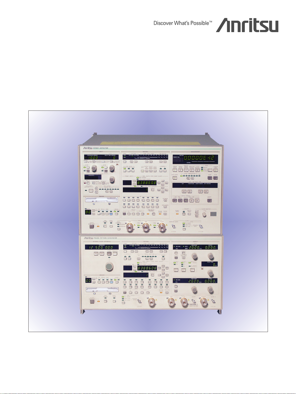
MP1763C/MP1764C/MP1764D
Pulse Pattern Generator/Error Detector
50 Mbit/s to 12.5 Gbit/s
• High-Quality, Low-Jitter, Low-Distortion Waveform Output
• Evaluation of Transmission Modules, Buses, Backplanes using
Differential/CDR Option
• 12.5 Gbit/s BERTS with Higher Performance and Lower Price
Page 2
High-Speed/Wide Band, High Quality Waveform and
Advanced Functions
Today’s demand for transfer of large amounts of data, such as
video, over the internet, is resulting in expansion of high-speed
transmission circuits and other infrastructure. In addition to the
previously used STM-64/OC-192 (9.95328 Gbit/s) standards, we
are also seeing use of 10.709225 Gbit/s (OTU-2), which includes
FEC coding, as well as 3.125 Gbit/s x 4 and 10.3125 Gbit/s in 10
Gbit Ethernet. Further more, the Fibre Channel file transfer protocol
at 4.25 Gbit/s is also coming into actual use.
As these new standards are settled upon, there is an urgent need
to be able to support evaluation of devices and circuits at these
higher bit rates.
Our MP1763C Pulse Pattern Generator and MP1764C/1764D Error
Detector are a BERTS (Bit Error Rate Test Set) supporting evaluation and testing of transmission equipment, high-speed devices,
optical modules, etc., at every stage from R&D through to manufacturing and production at speeds from 50 Mbit/s to 12.5 Gbit/s.
High-speed And Wide Band
One MP1763C/MP1764C can cover the band from STM-0/STS-1 to
10 Gbit Ethernet, STM-64/STS-192, OTU-2 and can be used with
4.25 Gbit/s Fibre Channel Systems.
Many Patterns
8 Mbit programmable pattern (corresponding to six frames of
•
STM-64/STS192)
PRBS patterns from 27– 1 to 231– 1
•
PRBS pattern with randomness and mark ratio variance for rigor-
•
ous testing
Alternating pattern
•
The MP1763C alternately sends normal and alarm patter ns to a
device for response testing.
Zero substitution pattern
•
This feature is effective for testing the clock regeneration of a 3R
repeater.
Pulse Pattern Generator
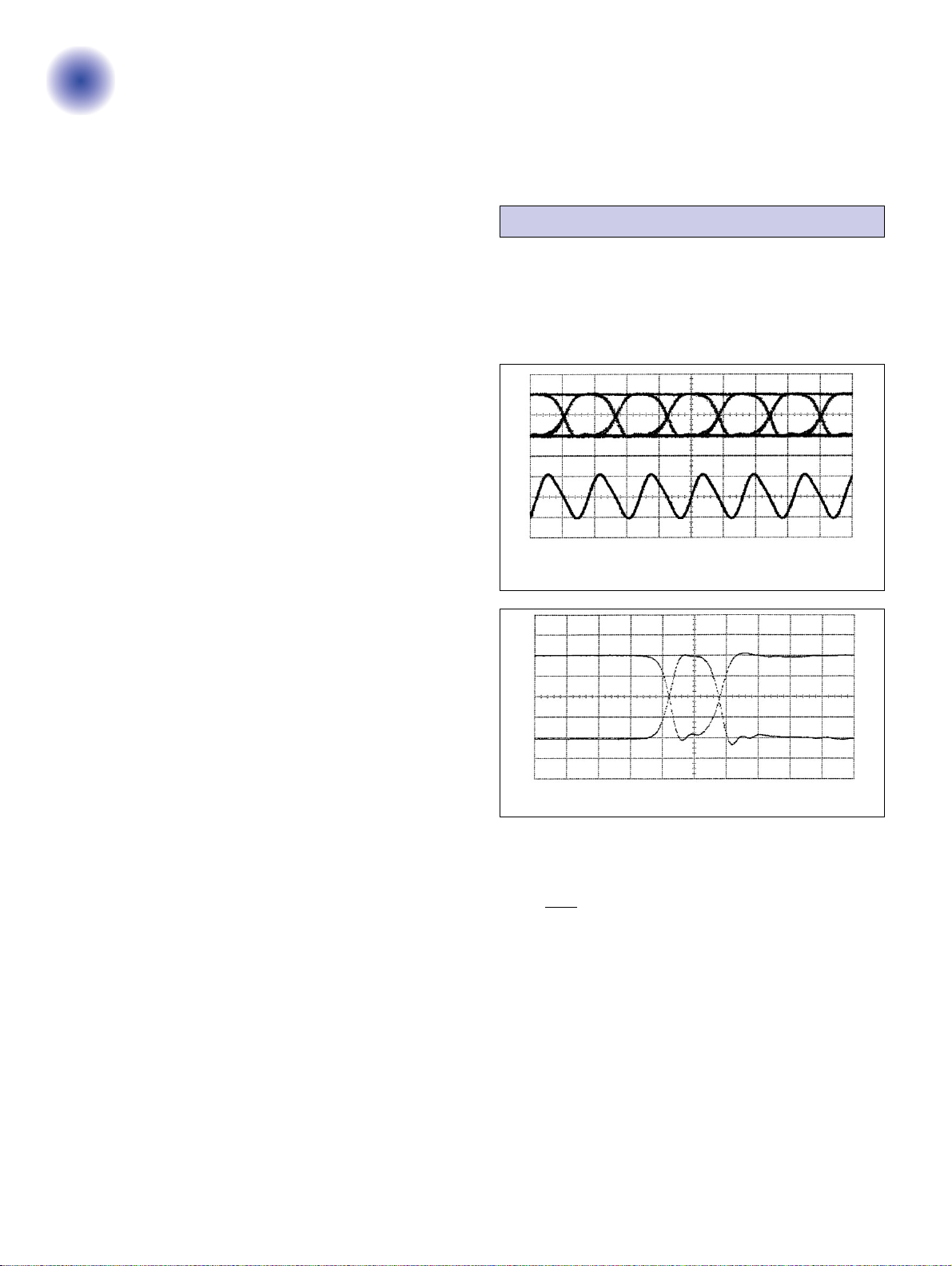
High-quality Waveform
tr/tf(10% to 90%): 30 ps (typical)
•
Jitter: 10 ps
•
Back termination for low waveform distortion
•
A pattern of isolated pulses which do not depend on mark ratios.
•
MP1763C output waveform
DATA output of 12.5 GHz (top trace)
CLOCK 1 output (bottom trace)
p-p
(typical)
H: 50 ps/div, V: 1 V/div
Location Changeable Pattern Synchronization Trigger
This feature makes it simple to monitor the waveform at any point
in a long word pattern.
High Q factor
•
A high Q factor can be obtained by back to back connection (typical value at 10 Gbit/s, PRBS 223– 1: 40 dB).
10 Gbit Ethernet I/O Interface Support
1/4 Differential Output (MP1763C-08 Option)
•
This outputs differential data at a rate of 1/4 of the standard output
(100 Mbit/s to 3.125 Gbit/s) as 4-bit parallel data. It can be used as
a data signal for evaluating high-speed devices such as XAUI and
SFI-4 P2 4 Lane devices used in 10 Gbit Ethernet and Fibre
Channel, and for evaluating high-speed buses and backplanes
such as PCI express.
Differential Input (MP1764C-02 Option)
•
This can be used for evaluation by inputting a high-speed differential signal used by XAUI, SFI-4P2 4Lane devices, PCI Express, etc.
Clock Recovery Function (MP1764C-03 Option)
•
The clock recovered from input data can be used as a trigger signal for error rate detection and waveform monitoring. Evaluation
does not require an external clock, and when used jointly with differential input, high-speed differential devices can be evaluated
without an external jig.
Bit rates from 62.5 Mbit/s to 11.1 Gbit/s are supported along with
4.25 Gbit/s used by Fibre Channel.
∗The MP1764D model ships with the MP1764C-02 (Differential input) and
MP1764C-03 (Clock recovery) options installed.
Isolated pattern (superimposition of 1/64 bits and 63/64 bits)
High Resolution Clock And Data Output
Output amplitude: 0.25 to 2 Vp-p (2 mV steps)
•
Output offset: –2 to +2 V (1 mV steps)
•
Delay (clock): –500 to +500 ps (1 ps steps)
•
DATA/DATA independently variable
•
Burst Signal Generation Using External Gate Signal
This feature is effective for optical fiber-loop testing, etc.
Parallel Output I/F (1/8, 1/4, 1/4 Differential)
1/8 parallel output is standard. 1/4 parallel output (Option 03) or
•
1/4 differential output (Option 08) can be selected exclusively.
It can be used as a MUX device and a data generator for WDM
•
transmission.
The 1/4 differential option provides 4-bit parallel output of differ-
•
ential data for the 1/4 rate standard output (100 Mbit/s to 3.125
Gbit/s). Similarly, a 1/4 rate clock can be output as a differential.
This can be used for performing detailed inspection of specifications and performance by use as a data signal for evaluation of
high-speed devices such as XAUI and SFI-4 P2 4 Lane devices
used in 10 Gbit Ethernet and Fibre Channel, and for evaluation of
high-speed buses and backplanes such as PCI express.
H: 50 ps/div, V: 0.5 V/div
2
Page 3
Error Detector Application Software
High Input Sensitivity And Wide Phase Margin
Input sensitivity: 50 mVp-p
•
(typical value at 10 Gbit/s, PRBS 223– 1)
Phase margin: 70 ps or more
•
(typical value at 10 Gbit/s, PRBS 223– 1)
Eye Margin Measurement
The phase margin and threshold margin can be measured and displayed for any error rate.
Burst Measurement
The burst data can be measured even for the PRBS and pro-
•
grammable patterns.
High-speed synchronization gain is achieved by a quick synchro-
•
nous method (typical sync. gain time at 10 Gbit/s, programmable
pattern length of 2048 bits, sync. threshold at 10
Selectivity BER Measurement In Bit Units
The bit errors can be measured for any block of 32-bit segments or
any bit.
Error Analysis Function (Option)
The pattern (256 bits in total) before and after a bit in which an
error occurred can be displayed. Also, insertion and omission
errors are displayed using different LED colors.
Differential Input Support (Option)
This supports direct input of high-speed differential signals used
•
by high-speed devices, buses and backplanes, such as XAUI,
SFI-4 P2 4 Lane and PCI Express.
Detailed evaluation is possible because independent thresholds
•
can be set for inverted and non-inverted data
–2
: 850 ns).
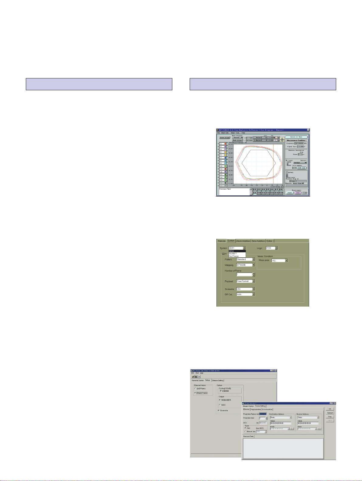
MX176400A Q/Eye Analysis Software
Eye diagram and eye margin automatic measurement
•
Displays a mask figure for the evaluation on the screen
•
Q-factor (ITU-T G.976) automatic measurement
•
∗ Single input unsupported; use at differential signal input is not supported.
MX176401A SDH/SONET Pattern Editor
Support OC-1 (STM-0) to OC-192c (STM-64c) mapping
•
Alarm addition (OOF, LOF, MS-AIS, REI, RDI)
•
BIP error addition (B1, B2, B3)
•
Support “No frame” pattern
•
Clock Recovery Function (Option)
The clock is recovered from the input data for use as a trigger
•
signal at error rate detection and waveform monitoring.
Evaluation does not require an external clock and the recovered
clock can also be used as an external clock, depending on the
setting.
A wide range of bit rates from 62.5 Mbit/s to 11.1 Gbit/s is sup-
•
ported, along with the 4.25 Gbit/s rate used by Fibre Channel.
When used in conjunction with differential input, it is also possible
•
to evaluate the latest high-speed differential devices that do not
use a clock without the need for an external jig.
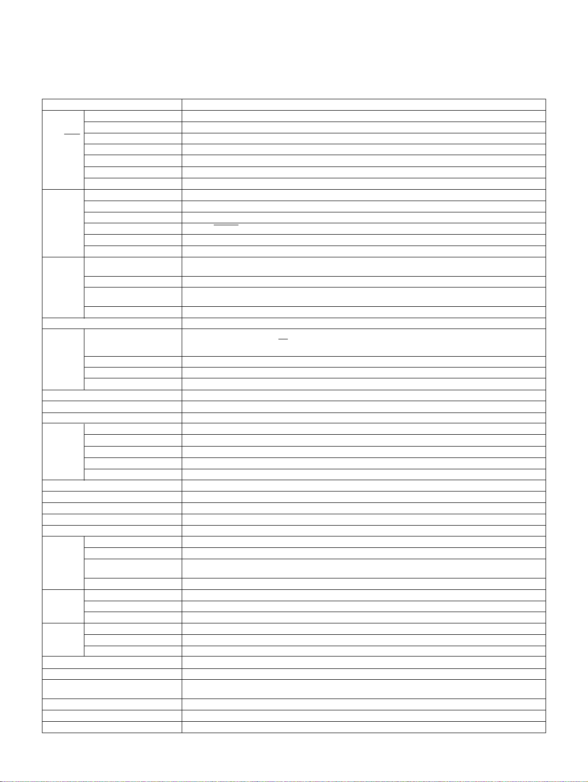
MX176403A GbE/10GbE Pattern Editing Software
(At Order Acceptance)
Supports Gbit Ethernet, 10 Gbit Ether net (10GBASE-R, XAUI)
•
frames
8B/10B, 64B/66B ON/OFF
•
Header, Payload editing function
•
CRC Auto-calculation
•
Bit Error, FCS Error insertion function
•
3
Page 4

MP1763C Pulse Pattern Generator
w
q
er t
q Internal Clock (Option 01)
Can be set in units of 1 kHz over the range from 50 MHz to 12.5
GHz
w Programmable Patterns
8-Mbit programmable pattern (can set six STM-64 frames)
•
4-Mbit alternate pattern
•
Zero substitution pattern
•
PRBS pattern from 27– 1 to 231– 1 selectable and its mark ratio
•
can be varied.
e Synchronous Output
The 1/64 clock or pattern SYNC selectable.
The trigger position variable for the pattern SYNC
y
r DATA Output
DATA/DATA complementary output with back termination
t CLOCK Output
CLOCK 1/CLOCK 1, CLOCK 2 (3 systems)
CLOCK 1/CLOCK 1 with back termination
y Parallel Output
Useful for testing an 8:1 MUX
(changeable to 1/4 speed output with option)
1/8 parallel output is standard. 1/4 parallel output (Option 03) or
•
1/4 differential output (Option 08) can be selected exclusively.
It can be used as a data generator for evaluation of MUX
•
devices, WDM transmission equipment, high-speed buses, backplanes, etc.
4
Page 5

MP1764D Error Detector
qw e
ty ui
r
o
q Eye Margin Measurement
Displays the phase margin and threshold margin.
w Synchronous Mode
High-speed sync. gain is achieved in frame and quick synchronous
modes.
e Error Analysis (Option 01)
The input pattern before and after a bit in which an error occurred
can be checked.
r Synchronous Threshold
The sync. gain and sync. loss conditions can be set.
t Non-Inverted DATA Input
Has a high input sensitivity of 50 mVp-p (typical value).
y Inverted DATA Input (Option 02)
At differential input, this uses inverted DATA input.
u CLOCK Input
Input CLOCK determining phase evaluation of 0 or 1
Option 03 with CLOCK recovery function makes input unnecessary
when inputting data with a supported bit rate.
i Regenerated CLOCK Output (Option 03)
This outputs the CLOCK regenerated from DATA.
o Two GPIB Connectors
One is used for an external printer.
5
Page 6

Specifications
MP1763C Pulse Pattern Generator
•
Operation frequency 0.05 to 12.5 GHz
Internal CLOCK (Option 01) SSB phase noise: ≤–85 dBc/Hz (0.05 to 4 GHz), ≤–80 dBc/Hz (4 to 8 GHz), ≤–75 dBc/Hz (8 to 10 GHz),
External CLOCK input level 0.4 to 2.5 Vp-p
Pseudorandom binary
sequence pattern (PRBS)
Pattern
DATA Pattern jitter ≤20 psp-p, typical 10 psp-p
output
CLOCK
output
1/8 DATA
and CLOCK
output
1/4 DATA
and CLOCK
output
(Option
∗
1
03)
1/4
Differential
DATA,
CLOCK
output
(Option
∗
1
08)
Sync. signal
output
Parameter memor y Media: 3.5 inch FD (2HD, 2DD), Format: MS-DOS (Rev. 3.1)
Operating temperature range 0˚ to +50˚C
Dimensions and mass 426 (W) x 221 (H) x 450 (D) mm, ≤33 kg
Power ≤400 VA
EMC EN61326: 1997/A2: 2001 (Class A), EN61000-3-2: 2000 (Class A), EN61326: 1997/A2: 2001 (Annex A)
LVD EN61010-1: 2001 (Pollution Degree 2)
DATA pattern DATA length: 2 to 8388608 bits
Alternate pattern A/B pattern DATA length: 128 to 4194304 bits (128 bit steps); Loop time: A, B pattern (1 to 127, 1 steps)
Zero substitution pattern Zero bit length: 1 to (pattern length – 1) bits; Pattern: 2n(n: 7, 9, 11, 15)
Error addition
Number of outputs 2 (DATA/DATA independently)
Amplitude 0.25 to 2 Vp-p, 2 mV steps
Offset voltage
Rise/fall time Typical 30 ps (10% to 90% of amplitude)
Waveform distortion (0-peak) ≤15% or ≤150 mV whichever is greater
Gating input Provided
Load impedance 50 Ω (with back termination)
Connector APC-3.5
DATA/DATA tracking DATA amplitude and offset voltage can be set to the same values as for DATA.
Cross point adjustment function
Number of outputs 3 (CLOCK 1/CLOCK 1, CLOCK 2)
Amplitude
Offset voltage
Rise/fall time Typical 30 ps (10% to 90% of amplitude)
Load impedance 50 Ω (CLOCK 1/CLOCK 1: with back termination)
Connector CLOCK 1/CLOCK 1: APC-3.5, CLOCK 2: SMA
Delay ±500 ps (1 ps steps)
Number of outputs DATA 8, CLOCK 1
Output level ECL
Connector SMA
Number of outputs DATA: 4, CLOCK: 1
Amplitude 0.5 to 2 Vp-p (2 mV steps)
Offset voltage VOH: –1.5 to +1.5 V (1 mV steps)
Connector SMA
Operation bit rate 1/4 DATA/DATA: 100 Mbit/s to 3.125 Gbit/s
Number of outputs 1/4 DATA/DATA differential 4 system. 1/4 CLOCK/CLOCK differential 1 system
Amplitude 0.5 to 2.0 Vp-p (2 mV steps), 1/4 DATA/DATA: All channels same settings
Offset voltage All channels same settings
Connector SMA
Number of outputs 1 (1/64 CLOCK, fixed position pattern, or variable position pattern selectable)
Output level 0/–1 V
Connector SMA
∗1: Select one type from three items
• 1/8 DATA and 1/8 CLOCK output
• 1/4 DATA and 1/4 CLOCK output (Option 03)
• 1/4 Differential DATA and 1/4 Differential CLOCK output (Option 08)
Frequency range: 0.05 to 12.5 GHz
≤–70 dBc/Hz (10 to 12.5 GHz)
n
Pattern: 2
Mark ratio: 1/2, 1/4, 1/8, 0/8 (1/2, 3/4, 7/8, 8/8 are possible with logic inversion)
Bit shifts number for mark ratio varied: 1, 3 bits selectable
Error rate: 10–n(n: 4, 5, 6, 7, 8, 9), and single error
External error injection: Provided
VOH: –2 to +2 V, 1 mV steps
Display: VOH, VTHor VOLselectable
The cross point of DATA/DATA outputs can be adjusted at semifixed resistor of side.
CLOCK 1/CLOCK 1: 0.25 to 2 Vp-p (2 mV steps)
CLOCK 2: 1 Vp-p
CLOCK 1/CLOCK 1: V
CLOCK 2: V
1/4 DATA/DATA: –1.0 to +2.5 V (VOH) (1 mV steps, PRBS 50 Ω/GND termination)
1/4 CLOCK/CLOCK: –1.5 to +1.5 V (V
– 1 (n: 7, 9, 11, 15, 20, 23, 31)
–2 to +2 V (1 mV steps)
OH
0 V fixed
OH
OH
∗At 10 kHz offset, 1 Hz bandwidth
) (1 mV steps, PRBS 50 Ω/GND termination)
∗
2
, Content: Pattern or other parameters
∗2: MS-DOS is a registered trademark of Microsoft Corporation.
6
Page 7
MP1764C/MP1764D Error Detector
•
Operation frequency 0.05 to 12.5 GHz
Input waveform NRZ
Input amplitude 0.25 to 2.0 Vp-p
DATA/DATA
input
(MP1764D
Option 02)
CLOCK
input
CLOCK
regeneration
function
(MP1764D
Option 03)
Auto search function Provided
Receive
pattern DATA pattern DATA length: 2 to 8388608 bits
Synchronous mode Normal, frame, quick
Synchronous threshold Preset value or 10–n(n: 2, 3, 4, 5, 6, 7, 8)
Error detection mode Omission insertion, total (selectable with DIP switch on rear panel)
Measurement item
Eye margin measurement function Provided
Error performance DATA calculation function
Measurement CH mask 1 to 32 ch (settable independently)
Block window Error for any block of 32-bit segments can be measured.
Error analysis (option 01) Pattern (256 bits in total) before and after bit in which error occurred is stored.
Auxiliary
output
Auxiliary
input
Sync. signal
output
Parameter memor y Media: 3.5 inch FD (2HD, 2DD), Format: MS-DOS (Rev. 3.1)
Operating temperature range 0˚ to +50˚C
Dimensions and mass
Power ≤300 VA
EMC EN61326: 1997/A2: 2001 (Class A), EN61000-3-2: 2000 (Class A), EN61326: 1997/A2: 2001 (Annex A)
LVD EN61010-1: 2001 (Pollution Degree 2)
Threshold voltage variable range
Phase margin ≥70 ps (typical value at 10 Gbit/s, PRBS 223– 1, at single ended input amplitude of 1 Vp-p)
Input sensitivity 50 mVp-p (typical value at 10 Gbit/s and PRBS 223– 1)
Termination Connected to GND or –2 V via a 50 Ω termination
Connector APC-3.5
Input waveform Rectangular wave (<0.5 GHz), rectangular or sine wave (≥0.5 GHz), duty factor: 50%
Input voltage 0.25 to 2.0 Vp-p
Input delay variable range ±500 ps (1 ps steps)
Polarity inversion CLOCK/CLOCK inversion possible
Termination Connected to GND or –2 V via a 50 Ω termination
Connector APC-3.5
Operation bit rate
CLOCK selection Internal/External
Continuous 0 s tolerance
(withstand)
Regenerated CLOCK output Output level: 1.0 ±0.25 V (AC coupling)
Pseudorandom binary
sequence pattern (PRBS)
Alternate pattern A/B pattern word length: 128 to 4194304 bits (128 bits steps), Number of loops: Controlled using external signal
Zero substitution pattern Zero bit length: 1 to (pattern length –1) bits, Pattern length: 2n(n: 7, 9, 11, 15)
Error rate 0.0000 x 10
Number of errors 0 to 9.9999 x 10
Error interval (asynchronous) 0 to 9999999 (interval: 1 ms, 10 ms, 100 ms, 1 s)
Error free interval (EFI) 0.0000% to 100.0000%
CLOCK frequency 0.05 to 12.5 GHz, (resolution: 1 kHz, accuracy: 10 ppm ±1 kHz)
Error output (direct) 1/128 OR error, Output level: 0/–1 V, Connector: SMA
Error output (stretched) Pulse width: 350 ns (typical), Output level: TTL, Connector: BNC
Alarm output (CLOCK loss, Output level: TTL
sync. loss) Connector: BNC
Sync. gain output Output level: 0/–1 V; Connector: SMA
External mask input Input level: 0/–1 V; Connector: SMA
Resync. input
Alternate A/B switching input Input level: ECL; Connector: SMA
Number of outputs 1 (1/32 CLOCK, fixed position pattern, or variable position pattern selectable)
Output level 0/–1 V
Connector SMA
–3.000 to +1.875 Vp-p (1 mV steps)
62.5 to 100 Mbit/s, 125 to 200 Mbit/s, 250 to 400 Mbit/s, 500 to 800 Mbit/s, 1,000 to 1,600 Mbit/s,
2,000 to 3,200 Mbit/s, 4,250 Mbit/s ±50 ppm, 9,900 to 11,100 Mbit/s
72 bit min.
n
Pattern: 2
Mark ratio: 1/2, 1/4, 1/8, 0/8 (1/2, 3/4, 7/8, 8/8 are possible with logic inversion.)
Number of AND bit shift at mark ratio setting: 1, 3 bits (selectable by using DIP switch on rear panel)
Provided
Input level: 0/–1 V; Connector: SMA
426 (W) x 221.5 (H) x 450 (D) mm, ≤30 kg (except Option 02, 03)
426 (W) x 266 (H) x 450 (D) mm, ≤35 kg (Option 02, 03)
– 1 (n: 7, 9, 11, 15, 20, 23, 31)
–16
to 1.0000 x 10
16
–0
∗
1,
Content: Pattern or other parameters
∗1: MS-DOS is a registered trade mark of Microsoft Corporation.
7
Page 8

Printed with environment-friendly
vegetable soybean oil ink.
Ordering Information
Please specify model/order number, name and quantity when ordering.
Model/Order No.
MP1763C Pulse Pattern Generator (50 Mbit/s to 12.5 Gbit/s)
J0500A
J0672F Semi-rigid cable (SMA-P · UT-85 · SMA-P), 10 cm: 1 pc
J0693A SMA cable (HRM202B-3D2W-HRM202B), 1 m: 1 pc
J0496 APC-3.5 J-J connector: 4 pcs
J0008 GPIB cable, 2 m: 1 pc
J0491 Power cord: 1 pc
Z0168 3.5-inch floppy disk (MF2HD-3.5MF): 2 pcs
Z0481 12.5G/3.2G BERTS application software demo: 1 pc
Z0306A Wrist strap: 1 pc
F0014 Fuse, 6.3 A (T6.3A250V): 1 pc
B0021 Protective cover (for 1MW · 5U): 1 pc
W1848AE MP1763C operation manual: 1 copy
W1849AE MP1763C GPIB operation manual: 1 copy
MP1763C-01 12.5 GHz Synthesizer (50 MHz to 12.5 GHz)
J0672D Semi-rigid cable (SMA-P · UT-85 · SMA-P), 7 cm
MP1763C-03 1/4 speed output
MP1763C-08 1/4 Differential Data Output Function
W2339AE MP1763C-08 operation manual
W2340AE MP1763C-08 GPIB operation manual
MP1764C Error Detector (50 Mbit/s to 12.5 Gbit/s)
MP1764D Error Detector (50 Mbit/s to 12.5 Gbit/s)
J0500A Semi-rigid cable
J0693A SMA cable (HRM202B-3D2W-HRM202B), 1 m: 3 pcs
J0496 APC-3.5 J-J connector: 2 pcs (MP1764C)
J0008 GPIB cable, 2 m: 2 pcs
J0776D
Main frame
Standard accessories
Semi-rigid cable (SMA-P · UT-141 · SMA-P), 0.5 m:
Option
(100 Mbit/s to 3.125 Gbit/s)
Main frame
Standard accessories
(SMA-P · UT-141 · SMA-P), 0.5 m: 2 pcs (MP1764C)
BNC cable (BNC-P · 3W · 3D · 2W · BNC-P · 3W), 2 m:
Name
2 pcs
4 pcs (MP1764D)
3 pcs (MP1764D)
2 pcs
Model/Order No.
J0491 Power cord (13 A): 1 pc
Z0168 3.5-inch floppy disk (MF2HD-3.5MF): 2 pcs
F0014 Fuse, 6.3 A: 1 pc
Z0306A Wrist strap: 1 pc
∗
1
B0021
∗
2
B0022
W1850AE MP1764C operation manual: 1 copy
W1851AE MP1764C GPIB operation manual: 1 copy
W2341AE MP1764D operation manual: 1 copy
W2342AE MP1764D GPIB operation manual: 1 copy
MP1764C-01 Error Analysis
MP1764C-02 Differential Data Input Function
MP1764C-03 Clock Recovery Function
MP1764D-01 Error Analysis
W2373AE MP1764C-02,03 operation manual
W2374AE MP1764C-02,03 GPIB Programming operation manual
MX176400A Q/Eye Analysis Software
MX176401A SDH/SONET Pattern Editor
MX176403A GbE/10GbE Pattern Editor
J0500B Semi-rigid cable (SMA-P · SX-36 · SMA-P), 1 m
J0322A Coaxial cable (SUC0FLEX104, 11SMA-11SMA), 0.5 m
J0322B Coaxial cable (SUC0FLEX104, 11SMA-11SMA), 1 m
J0007 408JE-104 GPIB cable, 1 m
Z0054 3.5-inch floppy disk (MF2DD-3.5MF)
MB24B Portable Test Rack
B0413A Carr ying case
B0163 Portable Quilting
B0044 Rack mount kit (for 1MW · 5U panel)
Z0416 3.5-inch head cleaning disk
J0498 Coaxial code, 0.5 m
J0499 Coaxial code, 1 m
J1141 50 Ω Ter minator
Protective cover (for 1MW · 5U): 1 pc
Front cover: 1 pc
Option
Application Software
Optional accessories
(rating current of power cord and plug: 20 A)
Name
∗1: For MP1764C
∗2: For MP1764C-02,03 and MP1764D
ANRITSU CORPORATION
1800 Onna, Atsugi-shi, Kanagawa, 243-8555 Japan
Phone: +81-46 - 223 - 1111
Fax: +81-46 - 296 - 1264
U.S.A.
•
ANRITSU COMPANY
TX OFFICE SALES AND SERVICE
1155 East Collins Blvd., Richardson, TX 75081, U.S.A.
Toll Free: 1- 800 - ANRITSU (267 - 4878)
Phone: +1-972- 644 - 1777
Fax: +1-972 - 644 - 3416
Canada
•
ANRITSU ELECTRONICS LTD.
700 Silver Seven Road, Suite 120, Kanata,
ON K2V 1C3, Canada
Phone: +1-613 - 591 - 2003
Fax: +1-613 - 591 - 1006
Brasil
•
ANRITSU ELETRÔNICA LTDA.
Praca Amadeu Amaral, 27 - 1 andar
01327-010 - Paraiso, Sao Paulo, Brazil
Phone: +55-11 - 3283 - 2511
Fax: +55-11 - 3886940
U.K.
•
ANRITSU LTD.
200 Capability Green, Luton, Bedfordshire LU1 3LU, U.K.
Phone: +44-1582 - 433280
Fax: +44-1582 - 731303
Germany
•
ANRITSU GmbH
Grafenberger Allee 54-56, 40237 Düsseldorf, Germany
Phone: +49-211 - 96855 - 0
Fax: +49-211 - 96855 - 55
France
•
ANRITSU S.A.
9, Avenue du Québec Z.A. de Courtabœuf 91951 Les
Ulis Cedex, France
Phone: +33-1 - 60 - 92 - 15 - 50
Fax: +33-1 - 64 - 46 - 10 - 65
Italy
•
ANRITSU S.p.A.
Via Elio Vittorini, 129, 00144 Roma EUR, Italy
Phone: +39-06 - 509 - 9711
Fax: +39-06 - 502 - 2425
Sweden
•
ANRITSU AB
Borgafjordsgatan 13 164 40 Kista, Sweden
Phone: +46-853470700
Fax: +46-853470730
Singapore
•
ANRITSU PTE LTD.
10, Hoe Chiang Road #07-01/02, Keppel Towers,
Singapore 089315
Phone: +65-6282 - 2400
Fax: +65-6282 - 2533
Printed on 100%
Recycled Paper
Catalog No. MP1763/1764-E- A -1- (4.00) Pr inted in Japan 2004-6 ddc
Specifications are subject to change without notice.
Hong Kong
•
ANRITSU COMPANY LTD.
Suite 923, 9/F., Chinachem Golden Plaza, 77 Mody
Road, Tsimshatsui East, Kowloon, Hong Kong, China
Phone: +852-2301 - 4980
Fax: +852-2301 - 3545
P. R. China
•
ANRITSU COMPANY LTD.
Beijing Representative Office
Room 1515, Beijing Fortune Building, No. 5 North
Road, the East 3rd Ring Road, Chao-Yang District
Beijing 100004, P.R. China
Phone: +86-10 - 6590 - 9230
Korea
•
ANRITSU CORPORATION
8F Hyun Juk Bldg. 832-41, Yeoksam-dong,
Kangnam-ku, Seoul, 135-080, Korea
Phone: +82-2 - 553 - 6603
Fax: +82-2 - 553 - 6604
Australia
•
ANRITSU PTY LTD.
Unit 3/170 Forster Road Mt. Waverley, Victoria, 3149,
Australia
Phone: +61-3 - 9558 - 8177
Fax: +61-3 - 9558 - 8255
Taiwan
•
ANRITSU COMPANY INC.
7F, No. 316, Sec. 1, NeiHu Rd., Taipei, Taiwan
Phone: +886-2 - 8751 - 1816
Fax: +886-2 - 8751 - 1817
040602
 Loading...