

Page 1
47
OPTICAL MEASURING INSTRUMENTS
GPIB
1
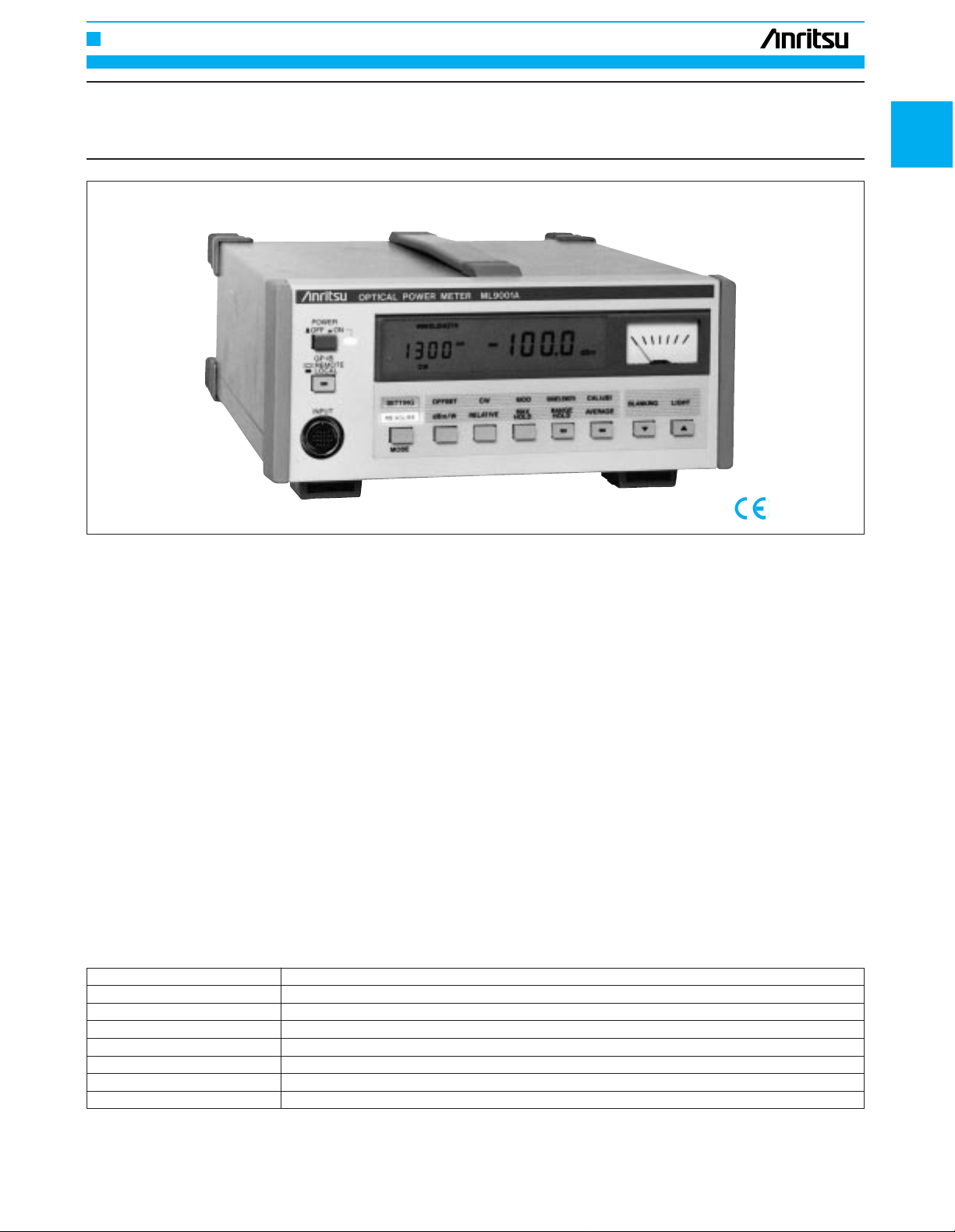
OPTICAL POWER METER
ML9001A
The ML9001A is a single-channel digital-display optical power meter.
It insures accuracy and linearity over a wide wavelength range and
greatly improves measurement reliability. It also has an improved basic performance. For example, measurement can be made over the wide
level range from –100 to +20 dBm because internal reflection in the
power sensors has been suppressed. The ML9001A also has many
new functions which make it easier to use than other power meters.
It can be used for all optical power measurements such as optical
fiber loss measurement and optical device performance evaluation.
Features
• Enables high-accuracy measurement
The ML9001A accurately and automatically calibrates all the power
sensors within the specified wavelength range and ensures a ±5%
accuracy at –23 dBm. It also has a ±0.15 dB linearity (–23 dBm reference value). The ML9001A extends the guaranteed accuracy range
of the measured values and enables high-accuracy measurement.
•One power sensor for repeater maintenance and long-distance
fiber loss measurement
The MA9612A Optical Power Sensor has ultra-high sensitivity. Its measurement level range is –100 to ±3 dBm in the 1.3 µm band and it
can sense either continuous light or modulated light. A single MA9612A
can measure the near-end and far-end outputs of a repeater as well
as measure long-distance fiber losses.
• Multi-Core fiber cable losses easily measured
For modulated light measurement, the ML9001A has 12 modulation
frequencies including 270 Hz. This meter can easily be used to
measure multi-core fiber cable losses by using it with the MG9002A
Stabilized Light Source (mounts up to 12 light source units).
• Interchangeable optical connectors
The optical connectors of all the power sensors accept adaptors. This
system allows the optical connectors to be interchanged so the ML9001A
can be quickly used with various optical connectors. Since the internal coating of the optical power sensors suppresses reflected light,
measurement errors are reduced in beam measurement (with or without
an optical fiber).
• Reduced measurement time
The ML9001A has a much better response speed and stability than
conventional optical power meters. With GPIB, it can measure at 30
ms/point so the measurement time can be reduced to less than 50%
of conventional automatic measurement.
• High-performance optical loss test set
Stacking the ML9001A with the MG9001A Stabilized Light Source
quickly configures a high-performance optical loss test set. It provides for selecting various light source units and enables the
ML9001A to measure all optical losses.
Specifications
• ML9001A Optical Power Meter
Indicator
Display 4 digit, W, W
(REL)
, dBm, dB
(REL)
selectable
Calibration coefficient Adjustable
Recorder output 1 V/full-scale, linear output
Range select Manual selection and automatic ranging
Measurement mode Continuous and modulated light*
1
Wavelength sensitivity correction Automatic correction in 1 nm steps
Data memory Max. 1000 data via GPIB
Dimensions and mass 213 (W) x 88 (H) x 250 (D) mm, ≤4 kg
Page 2
OPTICAL MEASURING INSTRUMENTS
48
EMC
*
11
EMC
*
11
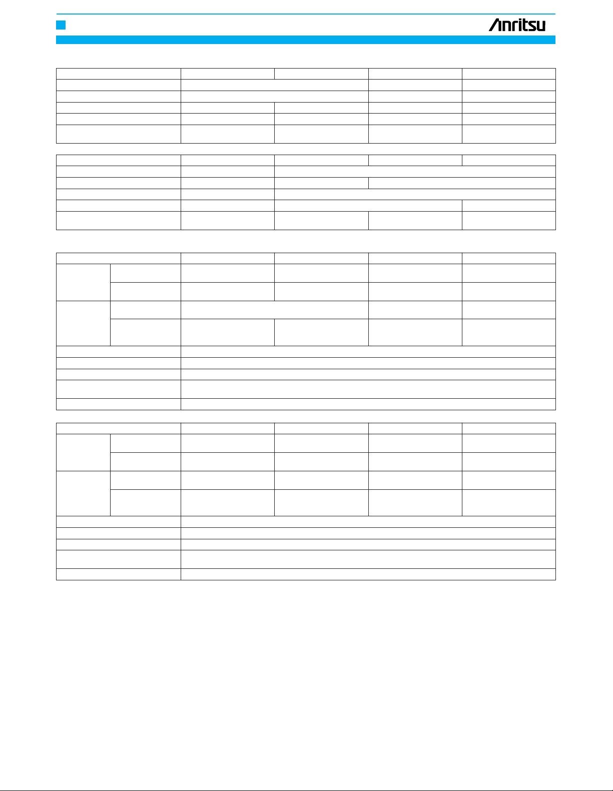
Model MA9411A/A1 MA9412A MA9413A MA9611A
Optical power
measurement
range
Measurement
accuracy
Resolution
Power
Operating temperature
Continuous light
–70 to +10 dBm
*
4
(0.1 nW to 10 mW)
–70 to +7 dBm
*
6
(0.1 nW to 5 mW)
±5%
*8 (0.5 to 0.95 µm)
±0.15 dB
*
10
(±0.45 dB for –70 to –60
dBm)
W, W
(REL)
display: 0.1 to 1%, dBm display: 0.01 dB, dB
(REL)
display: 0.001 dB
100/115/120/200/220 Vac
+10
–15
%, 240 Vac
+4
–15
%, 50/60/400 Hz, ≤40 VA
0° to 50°C
EN55011: 1991, Group 1, Class A
EN50082-1: 1992
±0.15 dB
*
10
(±0.45 dB for –90 to –80
dBm)
±0.15 dB
*
10
(±0.45 dB for –80 to –70
dBm)
±0.15 dB
*
10
(±0.45 dB for –70 to –60
dBm)
–90 to 0 dBm
*
4
(1 pW to 1 mW)
–90 to –3 dBm
*
6
(1 pW to 0.5 mW)
–80 to +10 dBm
*
4
(10 pW to 10 mW)
–90 to +7 dBm
*
6
(1 pW to 5 mW)
±4.5%
*
8
(0.85 µm)
±5%(0.5 to 0.95 µm)
–70 to +3 dBm
*
5
(0.1 nW to 2 mW)
–80 to 0 dBm
*
7
(10 pW to 1 mW)
±5%
*
9
(1.0 to 1.6 µm)
Modulated light
Absolute accuracy
(–23 dBm)
Linearity continuous
light: 23°C, –23
dBm as reference
Model MA9411A/A1
0.38 to 1.15 µm
Si photodiode
Direct to photodiode
40 (W) x 32 (H) x 62/73 (D)
mm
,
≤400 g
61 (W) x 42 (H) x 110 (D)
mm, ≤800 g
42 (W) x 47 (H) x 160 (D)
mm, ≤700 g
40 (W) x 32 (H) x 65 (D)
mm, ≤400 g
9.5 mm – 5 mm –
Connector
*
2
Direct to photodiode Connector
*
2
0.45 to 1.05 µm
Cooled-Si photodiode
0.75 to 1.7 µm
InGaAs photodiode
MA9412A MA9413A MA9611A
Wavelength range
Element
Active area diameter
Input type
Dimensions and mass
Sensor
Overall
Model MA9612A
0.75 to 1.7 µm 0.75 to 1.8 µm
InGaAs photodiode Ge photodiode
Connector
*
2
61 (W) x 42 (H) x 110 (D)
mm, ≤800 g
40 (W) x 32 (H) x 62/73 (D)
mm, ≤400 g
42 (W) x 47 (H) x 110 (D)
mm, ≤500 g
47 (W) x 61 (H) x 128 (D)
mm, ≤800 g
– 5 mm
Direct to photodiode Connector
*
3
Cooled-Ge photodiode
MA9711A/A1 MA9712A MA9714B
Wavelength range
Element
Active area diameter
Input type
Dimensions and mass
Model MA9612A MA9711A/A1 MA9712A MA9714B
Optical power
measurement
range
Measurement
accuracy
Resolution
Power
Operating temperature
Continuous light
–100 to +3 dBm
*
5
(0.1 pW to 2 mW)
–90 to 0 dBm
*
7
(1 pW to 1 mW)
±5%*
9
(1.0 to 1.6 µm) ±5%
*
9
(0.95 to 1.5 µm)
±0.15 dB
*
10
(±0.45 dB for –90 to –80
dBm)
W, W
(REL)
display: 0.1 to 1%, dBm display: 0.01 dB, dB
(REL)
display: 0.001 dB
100/115/120/200/220 Vac
+10
–15
%, 240 Vac
+4
–15
%, 50/60/400 Hz, ≤40 VA
0° to 50°C
EN55011: 1991, Group 1, Class A
EN50082-1: 1992
±0.15 dB
*
10
(±0.45 dB for –40 to –30
dBm)
±0.15 dB
*
10
(±0.45 dB for –60 to –50
dBm)
±0.15 dB
*
16
(–37 to +20
dBm, ±0.45 dBm for –47 to
–37 dBm)
–40 to +10 dBm
*
5
(0.1 µW to 10 mW)
–60 to +7 dBm
*
7
(1 nW to 5 mW)
–60 to +10 dBm
*
5
(1 nW to 10 mW)
–70 to +7 dBm
*
7
(0.1 nW to 5 mW)
±4.5% (1.3 µm)
±5%(0.95 to 1.6 µm)
–47 to +23 dBm
*
12
(20 nW to 200 mW)
–57 to +20 dBm
*
13
(2 nW to 100 mW)
±4.5% (1.55 µm)
*
14
±5%(0.95 to 1.6 µm)
*
15
Modulated light
Absolute accuracy
(–23 dBm)
Linearity continuous
light: 23°C, –23
dBm as reference
*
1: Twelve modulation frequencies including 270 Hz and 1 kHz
*
2: FC-type connector standard
*
3: Only for PC type SM fiber (10/125 µm, NA 0.1)
*
4: At 0.85 µm
*
5: At 1.3 µm
*
6: At 0.85 µm, 270 Hz
*
7: At 1.3 µm, 270 Hz
*
8: For wavelengths other than 0.85 µm, specified at 23° ±5°C
*
9: For wavelengths other than 1.3 µm, specified at 23° ±5°C
*
10: At 23° ±5°C
*
11: Electromagnetic compatibility
*
12: At 1.55 µm
*
13: At 1.55 µm, 270 Hz
*
14: At 1.55 µm, 0 dBm
*
15: At 0 dBm
*
16: Reference = 0 dBm
Note: When an optical fiber is used, performance is guaranteed for a fiber core diameter of up to 62.5 m and an NA of up to 0.29.
When any other fiber is used, a measurement error may occur.
Safety
EN61010-1: 1993 (Installation Category ΙΙ, Pollution Degree ΙΙ)
Safety
EN61010-1: 1993 (Installation Category ΙΙ, Pollution Degree ΙΙ)
Page 3

49
OPTICAL MEASURING INSTRUMENTS
1
• Optical connector options Ordering information
Please specify model/order number, name and quantity when ordering.
Option No. Optical connector
21 D4
22 RUNGE
23
*
1
Amphenol 906 type
34 DIAMOND (ø 3.5)
35
*
1
HP-SMA, Amphenol 905 type
36 Amphenol 905 type
38 ST
39 DIN
40 SC
41
*
2
TOCP172
43 HMS-10/A
45 FC
*
1: If adaptor mounted on MA9412A/9612A, repeatability may be reduced.
*
2: For MA9411A
Main frame
ML9001A Optical Power Meter
Standard accessories (for ML9001A)
J0313 Sensor connecting cord A, 2 m
(for MA9412A/9413A/9612A/9712A): 1 pc
J0314 Sensor connecting cord B, 2 m
(for MA9411A/A1, MA9611A and MA9711A/A1): 1 pc
J0017 Power cord, 2.5 m: 1 pc
F0004 Fuse, 0.4 A (T400MA250V): 2 pcs
F0007 Fuse, 0.8 A (T400MA250V): 2 pcs
W0420AE ML9001A operation manual: 1 copy
W0420BE ML9001A service manual: 1 copy
Optical power sensors
MA9411A/A1
*
1
Optical Power Sensor
MA9412A Optical Power Sensor
(with J0480A connector adaptor)
MA9413A Optical Power Sensor
MA9611A Optical Power Sensor
(with MA9005A Connector Adaptor)
MA9612A Optical Power Sensor
(with J0480A connector adaptor)
MA9711A/A1
*1Optical Power Sensor
MA9712A Optical Power Sensor
MA9714B
*
2
Optical Power Sensor
Optional accessories
MA9001B
*
3
Connector Adaptor (FC type, for MA9411A/MA9711A)
J0480A
*
3
Connector adaptor (FC type, for MA9412A)
J0480B
*
3
Connector adaptor (FC type, for MA9612A)
MA9005A
*
3
Connector Adaptor (FC type, for MA9611A)
MP92B
*
3
Connector Adaptor (FC type, for MA9413A/MA9712A)
MA9013A
*
3
Fiber Adaptor (with FC type plug, for fibers with 125 µm
clad dia., 0.25 to 1.0 mm jacket dia.)
MP916A Fiber Adaptor (for MA9002A and MP94A, for plastic
fiber with 1 mm dia.)
MP93A Fiber Adaptor (≤150 µm clad dia., 0.8 to 1.0 mm jacket
dia.)
MP94A Adaptor (for MA9413A/MA9712A, used with MP93A)
MA9002A Adaptor (for MA9411A/MA9711A, used with MP93A)
MA9805A Optical Attenuator (for MA9411A, 10 dB)
MA9306A Optical Attenuator (for MA9711A, 10 dB)
MZ8010A Optical Sensor Holder
(securely mounts MA9411A/A1 or MA9711A/A1 for
measuring light traveling through free space)
J0007 GPIB cable, 1 m
J0008 GPIB cable, 2 m
B0186 Front cover
J0592 Optical sensor connecting cord F (for MA97B)
J0617B
*
4
Replaceable optical connector (FC)
J0618D
*
4
Replaceable optical connector (ST)
J0618E
*
4
Replaceable optical connector (DIN)
J0618F
*
4
Replaceable optical connector (HMS-10/A)
J0619B
*
4
Replaceable optical connector (SC)
Model/order No. Name
*
1: MA9411A1 and MA9711A1 are lateral input sensors.
*
2: Specify one of FC, ST, DIN, SC or DIAMOND (HMS-10A).
When the connector type is not specified, FC is supplied.
*
3: The optical connector of the standard product is FC. Please specify the
option numbers along with model names shown in the tables, if you need
a different optical connector.
*
4: For MA9714B
Page 4

OPTICAL MEASURING INSTRUMENTS
50
ML9001A with sensor
Adaptors (option)
MA9412A Optical Power Sensor (0.38 to 1.15 µm)
MA9612A Optical Power Sensor (0.75 to 1.7µm)
MA9413A Optical Power Sensor (0.45 to 1.05 µm)
MA9412A Optical Power Sensor (0.75 to 1.8 µm)
MA9611A Optical Power Sensor (0.75 to 1.7 µm)
MA9411A Optical Power Sensor (0.38 to 1.15 µm)
MA9711A Optical Power Sensor (0.75 to 1.8 µm)
Sensor connecting cord A
Sensor connecting cord B
ML9001A Optical Power Meter
Fiber cord with plug
Pigtail fiber MA9013A Fiber Adaptor
Plastic fiber MP916A Fiber Adaptor
MP93A Fiber Adaptor
Light traveling through free space
MA9306A/9805A
Attenuator
MP94A Adaptor
MA9002A Adaptor
MA9411A/9711A
Optical Power Sensor
MA9413A/9712A
Optical Power Sensor
MA9611A Optical Power Sensor
(mounted on MA9005A)
MA9412A/9612A
Optical Power Sensor
MA9411A/9711A
Optical Power Sensor
MA9413A/9712A
Optical Power Sensor
MA9411A/9711A
Optical Power Sensor
MA9411A1/9711A1 Optical Power
Sensor (lateral input sensors)
MA9413A/9712A
Optical Power Sensor
MA9805A Attenuator
MA9306A Attenuator
MA9001B
Connector Adaptor
MP92B
Connector Adaptor
MA9805A Attenuator
MA9306A Attenuator
 Loading...