

Page 1

Data SheetData Sheet
MG3710A
Vector Signal Generator
100 kHz to 2.7 GHz
100 kHz to 4.0 GHz
100 kHz to 6.0 GHz
Page 2

Contents
Denitions, Conditions of Specications ................................................................................ 3
Frequency .............................................................................................................................. 4
Output Level .......................................................................................................................... 5
ATT Hold ................................................................................................................................ 9
Output Connector .................................................................................................................. 9
Maximum Reverse Input Power ............................................................................................ 9
Signal Purity .......................................................................................................................... 9
Analog Modulation ................................................................................................................. 16
Vector Modulation .................................................................................................................. 18
Arbitrary Waveform Generator ............................................................................................... 32
AWGN Generation Function .................................................................................................. 33
Sweep/List Function .............................................................................................................. 33
BER Measurement Function ................................................................................................. 34
Connector .............................................................................................................................. 35
Display ................................................................................................................................... 36
General .................................................................................................................................. 36
Page 3

Denitions
Typical (typ.)
Performance not warranted. Must products meet typical performance.
Nominal (nom.)
Values not warranted. Included to facilitate application of product.
Measured (meas)
Performance not warranted. Data actually measured by randomly selected measuring instruments.
Conditions of Specications
The conditions are as follows unless specied otherwise.
CW/Modulation Mode
After 30-minute warm-up (at constant ambient temperature)
Pulse Modulation: Off
ATT Hold: Off
Optimize S/N Mode: Off
: f > 2.7 GHz: Use MG3710A-034/036, MG3710A-064/066
∗
f > 4 GHz: Use MG3710A-036, MG3710A-066
Modulation Mode only
Waveform pattern RMS value: At RMSw (Linear value) and each combination less than following ranges:
–3.00 dB ≤ RMSnom ≤ +3.00 dB
RMSnom = 20•log (RMSw/4628) (16-bit Data)
RMSnom = 20•log (RMSw/2314) (15-bit Data)
RMSnom = 20•log (RMSw/1157) (14-bit Data)
after CAL
: Applies to MG3710A-062/064/066
∗
Data Sheet
l
MG3710A 3
Page 4

Frequency
Setting Range
1st SG
9 kHz to 2.7 GHz [MG3710A-032]
9 kHz to 4 GHz [MG3710A-034]
9 kHz to 6 GHz [MG3710A-036]
2nd SG
9 kHz to 2.7 GHz [MG3710A-062]
9 kHz to 4 GHz [MG3710A-064]
9 kHz to 6 GHz [MG3710A-066]
Resolution: 0.01 Hz
Phase Offset
Range: –180.00 deg. to +180.00 deg.
Resolution: 0.01 deg.
Switching Speed
≤600 µs
(Time from trigger input to nal frequency ±0.1 ppm or within 100 Hz when executing List function at frequency of >187.5 MHz)
Internal Reference Oscillator
without MG3710A-001/002
Aging rate: ±1 × 10⁻⁶/year
Temperature characteristics: ±2.5 × 10⁻⁶ (5° to 45°C)
with MG3710A-001
Start-up characteristics: 23°C, Referenced to frequency at 24 hours after power-on
Aging rate: ±1 × 10
Temperature characteristics: ±2 × 10⁻⁹ (5° to 45°C)
with MG3710A-002
Start-up characteristics: 23°C, Referenced to frequency at 24 hours after power-on
Aging rate: ±1 × 10⁻⁷/year
Temperature characteristics: ±2 × 10⁻⁸ (5° to 45°C)
±1 × 10⁻⁹ (7.5 minutes after power-on)
–10
/month
±5 × 10⁻⁷ (2 minutes after power-on)
±5 × 10⁻⁸ (5 minutes after power-on)
4 Data Sheet
l
MG3710A
Page 5
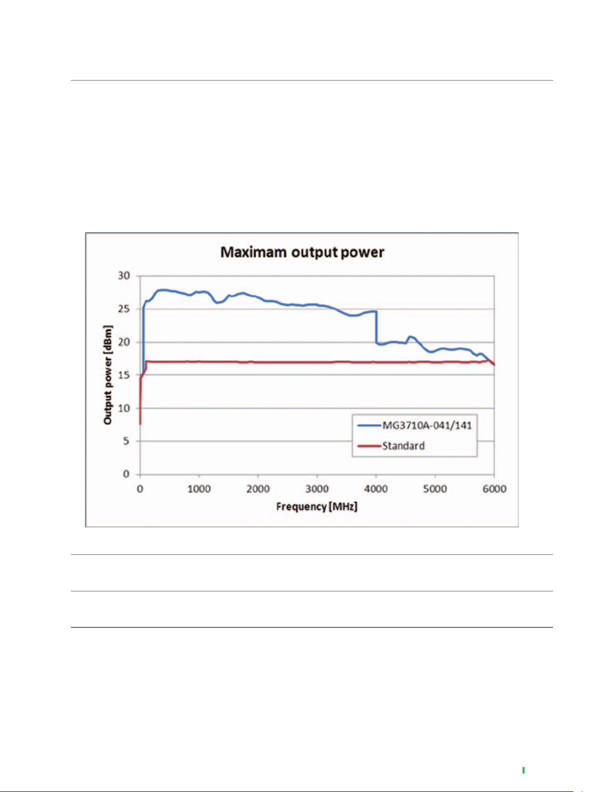
Output Level
Setting Range
without MG3710A-043/073
–110 to +17 dBm [without MG3710A-041/042], [without MG3710A-071/072]
–110 to +30 dBm [with MG3710A-041, without MG3710A-042], [with MG3710A-071, without MG3710A-072]
–144 to +17 dBm [without MG3710A-041, with MG3710A-042], [without MG3710A-071, with MG3710A-072]
–144 to +30 dBm [with MG3710A-041/042], [with MG3710A-071/072]
with MG3710A-043/073
–110 to +17 dBm [without MG3710A-041/042], [without MG3710A-071/072]
–110 to +25 dBm [with MG3710A-041, without MG3710A-042], [with MG3710A-071, without MG3710A-072]
–144 to +17 dBm [without MG3710A-041, with MG3710A-042], [without MG3710A-071, with MG3710A-072]
–144 to +25 dBm [with MG3710A-041/042], [with MG3710A-071/072]
Unit
dBm, dBµV (Terminated, Open)
Resolution
0.01 dB
Switching Speed
≤600 µs
(Time from trigger input to nal level ±0.2 dB at frequency of >187.5 MHz)
(Output Level: ≤+7 dBm [without MG3710A-041], [without MG3710A-071])
(meas)
Data Sheet
l
MG3710A 5
Page 6
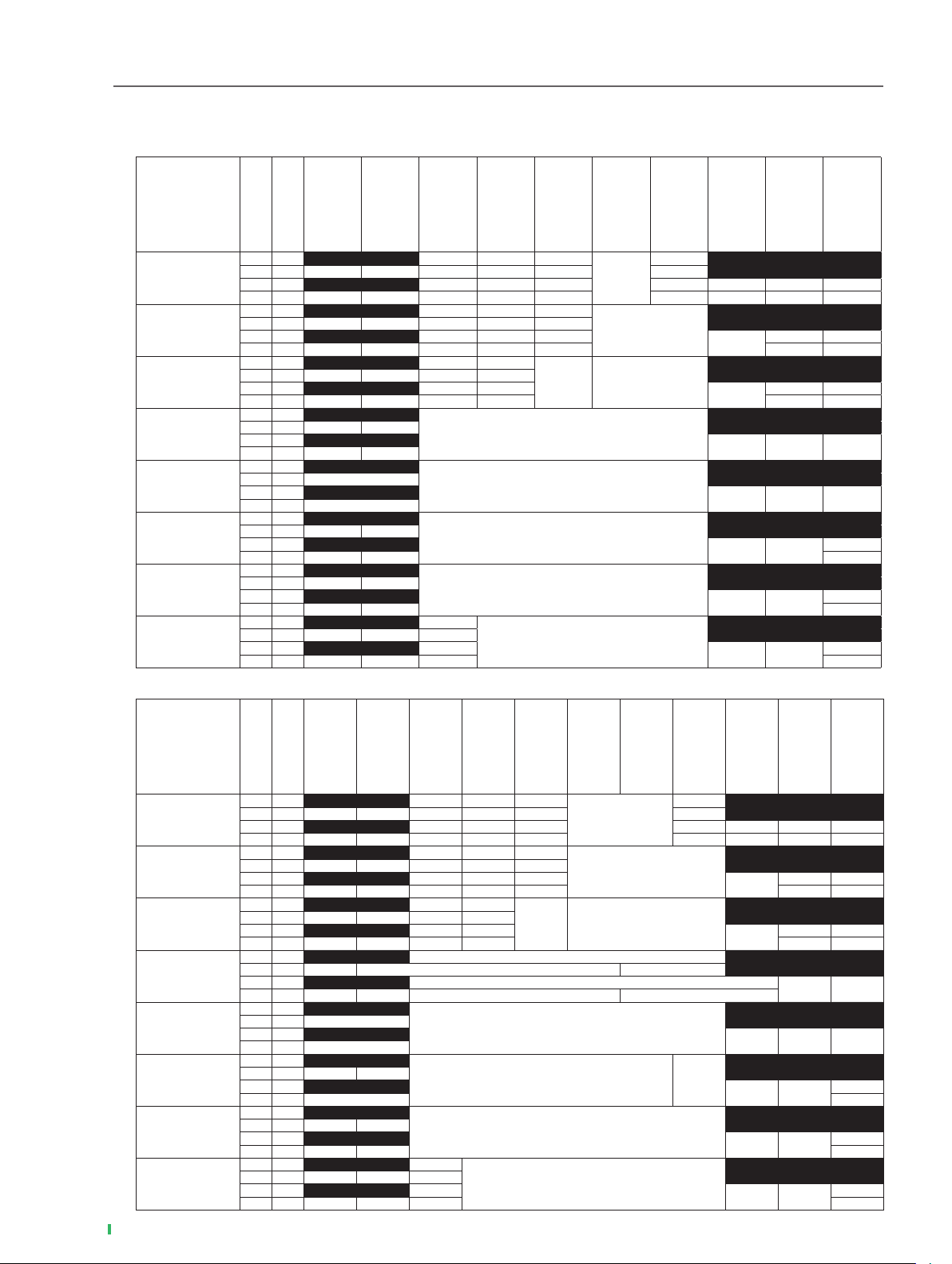
Level Accuracy
18° to 28°C, CW
without Reverse Power Protection [without MG3710A-043], [without MG3710A-073]
Frequency range
Low Power Extension
MG3710A-042/072
High Power Extension
MG3710A-041/071
≤+23 dBm
>+20 dBm
≤+20 dBm
>+13 dBm
≤+13 dBm
>+11 dBm
≤+11 dBm
>+10 dBm
±0.7 dB
±0.5 dB
±0.5 dB
±0.7 dB
±0.8 dB
100 kHz ≤ f < 1 MHz
1 MHz ≤ f < 10 MHz
10 MHz ≤ f < 50 MHz
50 MHz ≤ f < 400 MHz
400 MHz ≤ f ≤ 3 GHz
3 GHz < f ≤ 4 GHz
4 GHz < f ≤ 5 GHz
5 GHz < f ≤ 6 GHz
without without
without
with — — — — — —
without
with
with with — — — — — — — — —
without without
without
with — — — — —
without
with
with with — — — — — — —
without without
without
with — — — —
without
with
with with — — — — — —
without without
without
with — ±0.6 dB
without
with
with with — ±0.6 dB
without without
without
with ±0.6 dB
without
with
with with ±0.6 dB
without without
without
with — ±0.7 dB
with
without
with with — ±0.7 dB —
without without
without
with — —
without
with
with with — — —
without without
without
with — — —
without
with
with with — — — —
— — —
— — — — — — —
— — —
— — —
— —
— —
—
—
≤+10 dBm
>+5 dBm
(typ.)
±0.8 dB
≤+5 dBm
>–100 dBm
±0.5 dB
(typ.)
±0.5 dB (typ.)
±0.5 dB (typ.)
≤–100 dBm
>–110 dBm
—
≤–110 dBm
>–120 dBm
≤–120 dBm
±0.5 dB
(typ.)
±0.5 dB
(typ.)
±0.5 dB ±0.7 dB
±0.5 dB ±0.7 dB
±0.7 dB
±1.0 dB
±1.0 dB
— —
— —
±2.5 dB
(typ.)
±2.5 dB
(typ.)
±2.5 dB
(typ.)
>–127 dBm
±1.5 dB
(typ.)
±1.5 dB
(typ.)
≤–127 dBm
>–136 dBm
—
—
—
6 Data Sheet
with Reverse Power Protection [with MG3710A-043], [with MG3710A-073]
Frequency range
Low Power Extension
MG3710A-042/072
High Power Extension
MG3710A-041/071
≤+20 dBm
>+17 dBm
≤+17 dBm
>+10 dBm
≤+10 dBm
>+8 dBm
≤+8 dBm
100 kHz ≤ f < 1 MHz
1 MHz ≤ f < 10 MHz
10 MHz ≤ f < 50 MHz
50 MHz ≤ f < 400 MHz
400 MHz ≤ f ≤ 3 GHz
3 GHz < f
4 GHz < f
< f ≤
5 GHz
l
MG3710A
≤
≤
4 GHz
5 GHz
6 GHz
without without
without
with — — — — — —
without
with
with with — — — — — — — — —
without without
without
with — — — — —
without
with
with with — — — — — — —
without without
without
with — — — —
without
with
with with — — — — — —
without without
without
with — ±0.6 dB ±0.5 dB
without
with
with with — ±0.6 dB ±0.6 dB ±0.5 dB
without without
without
with ±0.6 dB
without
with
with with ±0.6 dB
without without
without
with — ±0.7 dB
without
with
with with ±0.7 dB —
without without
without
with — —
without
with
with with — — —
without without
without
with — — —
without
with
with with — — — —
— — —
— — — — — — —
— — —
— — —
— —
— —
—
—
>+7 dBm
≤+7 dBm
>+2 dBm
≤+2 dBm
>–2 dBm
≤–2 dBm
>–100 dBm
±0.5 dB (typ.)
±0.5 dB (typ.)
±0.7 dB
(typ.)
±0.5 dB
±0.5 dB
±0.7 dB ±0.8 dB
±0.8 dB
±0.5 dB (typ.)
±0.5 dB
±0.8 dB
≤–100 dBm
>–110 dBm
—
±0.5 dB
±0.5 dB
±0.7 dB ±1.0 dB
±1.0 dB
±1.0 dB
±1.0 dB
≤–110 dBm
(typ.)
(typ.)
>–120 dBm
— —
— —
±0.7 dB
±2.5 dB
(typ.)
±2.5 dB
(typ.)
±2.5 dB
(typ.)
≤–120 dBm
>–127 dBm
±1.5 dB
(typ.)
±1.5 dB
(typ.)
≤–127 dBm
>–136 dBm
—
—
—
Page 7
(meas)
(meas)
Data Sheet
l
MG3710A 7
Page 8

Level Linearity
18° to 28°C, CW
without Reverse Power Protection [without MG3710A-043], [without MG3710A-073]
Referenced to level: –7 dBm
Frequency range
50 MHz ≤ f < 400 MHz
400 MHz ≤ f ≤ 3 GHz
3 GHz < f ≤ 4 GHz
4 GHz < f ≤ 6 GHz
Low Power Extension
MG3710A-042/072
without
with ±0.2 dB (typ.)
without
with ±0.2 dB (typ.)
without
with ±0.3 dB (typ.)
without
with —
with Reverse Power Protection [with MG3710A-043], [with MG3710A-073]
Referenced to level: –10 dBm
Frequency range
50 MHz ≤ f < 400 MHz
400 MHz ≤ f ≤ 3 GHz
3 GHz < f ≤ 4 GHz
4 GHz < f ≤ 6 GHz
Low Power Extension
MG3710A-042/072
without
with
without
with
without
with
without without/with
with
High Power Extension
MG3710A-041/071
without/with
High Power Extension
MG3710A-041/071
without/with
without
with
without
with
≤+2 dBm
>–110 dBm
±0.2 dB (typ.)
±0.2 dB (typ.)
±0.3 dB (typ.)
±0.3 dB (typ.)
≤ –1 dBm
>–100 dBm
±0.2 dB (typ.)
±0.2 dB (typ.)
±0.3 dB (typ.) ±0.4 dB (typ.)
±0.3 dB (typ.) ±0.4 dB (typ.)
≤–110 dBm
>–120 dBm
≤ –100 dBm
>–110 dBm
8 Data Sheet
l
MG3710A
(meas)
Page 9

ATT Hold
At move to ATT Hold, can adjust output level in 0.01-dB steps over ±10 dB range based on output level without stopping output (however, hi/lo
limits determined by level setting range)
Output Connector
Connector
N-J Connector, 50Ω (Front panel)
VSWR
without MG3710A-043
(Output Level: ≤–7 dBm)
1.45 (50 MHz ≤ f ≤ 3 GHz)
1.65 (3 GHz < f ≤ 4 GHz)
1.9 (4 GHz < f ≤ 6 GHz)
with MG3710A-043
(Output Level: ≤–10 dBm)
1.45 (50 MHz ≤ f ≤ 3 GHz)
1.65 (3 GHz < f ≤ 4 GHz)
1.9 (4 GHz < f ≤ 6 GHz)
without MG3710A-073
(Output Level: ≤–7 dBm)
1.45 (50 MHz ≤ f ≤ 3 GHz)
1.65 (3 GHz < f ≤ 4 GHz)
1.9 (4 GHz < f ≤ 6 GHz)
with MG3710A-073
(Output Level: ≤–10 dBm)
1.45 (50 MHz ≤ f ≤ 3 GHz)
1.65 (3 GHz < f ≤ 4 GHz)
1.9 (4 GHz < f ≤ 6 GHz)
Maximum Reverse Input Power
±50 VDC (max.)
without MG3710A-043
2 W (nom.)
with MG3710A-043
20 W (1 MHz < Frequency of Reverse Input Power ≤ 2 GHz) (nom.)
10 W (2 GHz < Frequency of Reverse Input Power ≤ 6 GHz) (nom.)
without MG3710A-073
2 W (nom.)
with MG3710A-073
20 W (1 MHz < Frequency of Reverse Input Power ≤ 2 GHz) (nom.)
10 W (2 GHz < Frequency of Reverse Input Power ≤ 6 GHz) (nom.)
Signal Purity
Harmonic Spurious
(CW, Optimize S/N: Off)
without MG3710A-043, or without MG3710A-073
without MG3710A-041
<–30 dBc (Output Level: ≤+4 dBm, 10 MHz ≤ f ≤ 3 GHz)
<–30 dBc (Output Level: ≤+4 dBm, f >3 GHz)
with MG3710A-041
<–30 dBc (Output Level: ≤+4 dBm, 10 MHz ≤ f < 50 MHz)
<–30 dBc (Output Level: ≤+12 dBm, 50 MHz ≤ f ≤ 3 GHz)
<–30 dBc (Output Level: ≤+4 dBm, f >3 GHz)
with MG3710A-043, or with MG3710A-073
without MG3710A-041
<–30 dBc (Output Level: ≤+1 dBm, 10 MHz ≤ f ≤ 3 GHz)
<–30 dBc (Output Level: ≤+1 dBm, f >3 GHz)
with MG3710A-041
<–30 dBc (Output Level: ≤+1 dBm, 10 MHz ≤ f < 50 MHz)
<–30 dBc (Output Level: ≤+9 dBm, 50 MHz ≤ f ≤ 3 GHz)
<–30 dBc (Output Level: ≤+4 dBm, f >3 GHz)
Data Sheet
l
MG3710A 9
Page 10
Non-harmonic Spurious
(CW, <–30 dBm ≤ Output Level ≤ +5 dBm, Offset: ≥10 kHz)
<–62 dBc, –70 dBc (typ.) (100 kHz ≤ f ≤ 187.5 MHz)
<–68 dBc, –76 dBc (typ.) (187.5 MHz < f ≤ 750 MHz)
<–62 dBc, –76 dBc (typ.) (750 MHz < f ≤ 1.5 GHz)
<–56 dBc, –70 dBc (typ.) (1.5 GHz < f ≤ 3 GHz)
<–50 dBc, –64 dBc (typ.) (3 GHz < f ≤ 6 GHz)
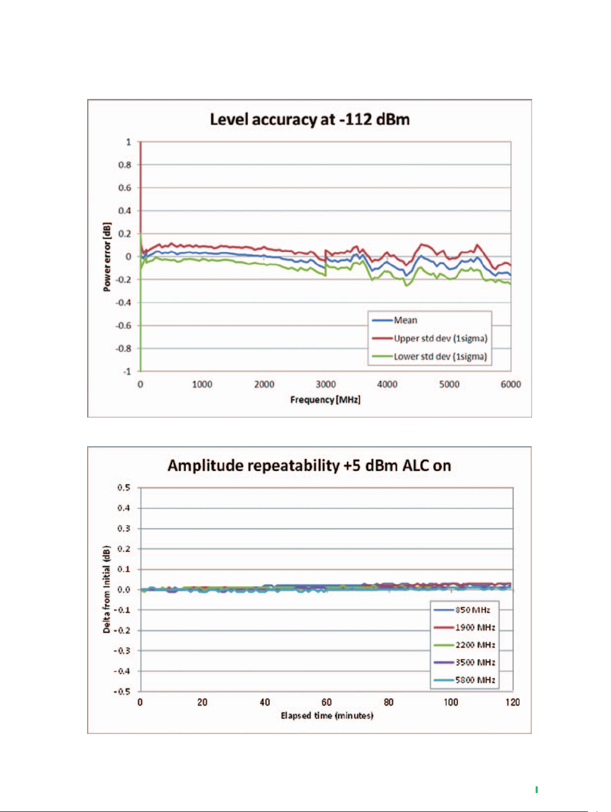
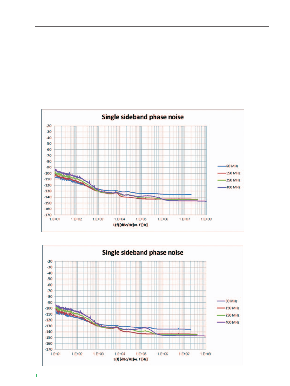
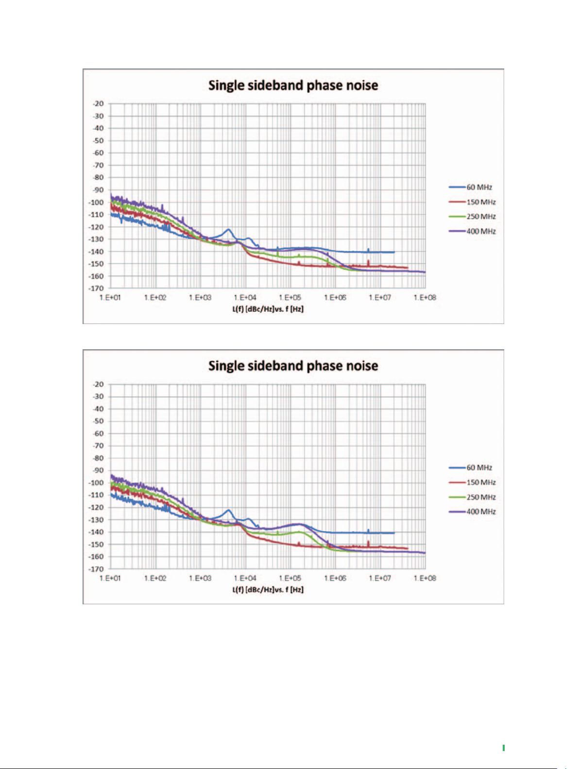
SSB Phase Noise
(CW, Phase Noise Optimization: <200 kHz, Offset: 20 kHz)
<–140 dBc/Hz (nom.) (100 MHz)
<–131 dBc/Hz (typ.) (1 GHz)
<–125 dBc/Hz (typ.) (2 GHz)
■ 60/150/260/400 MHz, CW, Optimize S/N: Off, with MG3710A-002
10 Data Sheet
l
MG3710A
Phase Noise Optimization: <200 kHz
Phase Noise Optimization: >300 kHz
(meas)
(meas)
Page 11
■ 60/150/260/400 MHz, CW, Optimize S/N: On, with MG3710A-002
Phase Noise Optimization: <200 kHz
(meas)
Phase Noise Optimization: >300 kHz
(meas)
Data Sheet
l
MG3710A 11
Page 12

■ 60/150/260/400 MHz, Mod = On, with MG3710A-002
Phase Noise Optimization: <200 kHz
Phase Noise Optimization: >300 kHz
(meas)
(meas)
12 Data Sheet
l
MG3710A
Page 13

■ 850 MHz, 1/1.9/2.2/3.5/5.8 GHz, CW, Optimize S/N: Off, with MG3710A-002
Phase Noise Optimization: <200 kHz
(meas)
Phase Noise Optimization: >300 kHz
(meas)
Data Sheet
l
MG3710A 13
Page 14

■ 850 MHz, 1/1.9/2.2/3.5/5.8 GHz, CW, Optimize S/N: On, with MG3710A-002
Phase Noise Optimization: <200 kHz
Phase Noise Optimization: >300 kHz
(meas)
(meas)
14 Data Sheet
l
MG3710A
Page 15

■ 850 MHz, 1/1.9/2.2/3.5/5.8 GHz, Mod = On, with MG3710A-002
Phase Noise Optimization: <200 kHz
Phase Noise Optimization: >300 kHz
(meas)
(meas)
Data Sheet
l
MG3710A 15
Page 16

Analog Modulation
Optimize Function
Spurious Mode
Mode to control spurious problem. Controls spurious generated by the modulator.
Distortion Mode
Mode to control distortion problem. Optimizes the setting automatically to avoid distortions.
This mode can be used when the output frequency is 7 MHz or higher .
Amplitude Modulation (AM)
Internal modulation only; Specications for modulated CW signal
AM Depth Type
Lin: Displays the AM depth type in linear.
Exp: Displays the AM depth type into the log format.
AM Depth
Range: 0 to 100%
Resolution: 0.1%
(Peak Level: ≤+4 dBm, AM Depth Type: Lin, after CAL)
AM Depth Error
<3% of setting + 2% (nom.) (100 kHz ≤ f < 98 MHz, Modulation Rate: 1 kHz, AM Source = Sine, AM Depth m: ≤ 90%)
<2% of setting + 1% (nom.) (98 MHz ≤ f ≤ 2.7 GHz, Modulation Rate: 1 kHz, AM Source = Sine, AM Depth m: ≤ 90%)
Distortion
<2% (nom.) (100 kHz ≤ f < 98 MHz, Modulation Rate: 1 kHz, AM Source = Sine, AM Depth m: 30%)
<2.5% (nom.) (100 kHz ≤ f < 98 MHz, Modulation Rate: 1 kHz, AM Source = Sine, AM Depth m: 90%)
<0.5% (nom.) (98 MHz ≤ f ≤ 2.7 GHz, Modulation Rate: 1 kHz, AM Source = Sine, AM Depth m: 30%)
<0.5% (nom.) (98 MHz ≤ f ≤ 2.7 GHz, Modulation Rate: 1 kHz, AM Source = Sine, AM Depth m: 90%)
Modulation Frequency Response
Applied only to the internal modulation (Int) when MG3710A-050/080 is not installed.
100 kHz ≤ f < 98 MHz, Bandwidth: ±1.5 dB
Modulation Ratio m = 30%
Int: 0.1 Hz ≤ Modulation Rate ≤ 20 kHz (nom.)
Ext DC coupling: DC ≤ Modulation Rate ≤ 20 kHz (nom.)
Ext AC coupling: 20 Hz ≤ Modulation Rate ≤ 20 kHz (nom.)
Modulation Ratio m = 90%
Int: 0.1 Hz ≤ Modulation Rate ≤ 20 kHz (nom.)
Ext DC coupling: DC ≤ Modulation Rate ≤ 20 kHz (nom.)
Ext AC coupling: 20 Hz ≤ Modulation Rate ≤ 20 kHz (nom.)
98 MHz ≤ f ≤ 2700 MHz, Bandwidth: ±1 dB
Modulation Ratio m = 30%
Int: 0.1 Hz ≤ Modulation Rate ≤ 20 kHz (nom.)
Ext DC coupling: DC ≤ Modulation Rate ≤ 20 kHz (nom.)
Ext AC coupling: 20 Hz ≤ Modulation Rate ≤ 20 kHz (nom.)
Modulation Ratio m = 90%
Int: 0.1 Hz ≤ Modulation Rate ≤ 20 kHz (nom.)
Ext DC coupling: DC ≤ Modulation Rate ≤ 20 kHz (nom.)
Ext AC coupling: 20 Hz ≤ Modulation Rate ≤ 20 kHz (nom.)
16 Data Sheet
Frequency Modulation (FM)
Internal modulation only; Specications for modulated CW signal
FM Deviation
Range: 0 Hz to 40 MHz, or [50 MHz – Modulation Rate] (smaller value)
Resolution: 0.1 Hz
(Output Level: ≤+4 dBm, 100 kHz + 2 × (Modulation Rate + 2 × FM Deviation) ≤ f ≤ 2.7 GHz, after CAL)
Deviation Accuracy
<2% of setting + 20 Hz (nom.) (Modulation Rate: 1 kHz, FM Source = Sine, 20 Hz ≤ FM Deviation ≤ 40 kHz)
Distortion
< 0.5% (nom.) (Modulation Rate: 1 kHz, FM Source = Sine, FM Deviation: 22.5 kHz)
< 1% (nom.) (Modulation Rate: 1 kHz, FM Source = Sine, FM Deviation: 3.5 kHz)
Modulation Frequency Response
Applied only to the internal modulation (Int) when MG3710A-050/080 is not installed.
Deviation: 40 kHz, Bandwidth: ±1 dB
Int: 20 Hz ≤ Modulation Rate ≤ 20 kHz (nom.)
Ext DC coupling: DC ≤ Modulation Rate ≤ 20 kHz (nom.)
Ext AC coupling: 20 Hz ≤ Modulation Rate ≤ 20 kHz (nom.)
l
MG3710A
Page 17

Phase Modulation (PM)
Internal modulation only; Specications for modulated CW signal
PM Deviation
Range: 0 rad. to 160 rad., or [40 MHz ÷ Modulation Rate] (smaller value)
Resolution: 0.001 rad.
(Output Level: ≤+4 dBm, 100 kHz + 2 × (Modulation Rate + 2 × PM Deviation × Modulation Rate) ≤ f ≤ 2.7 GHz, after CAL)
Deviation Accuracy
<2% of setting + 0.02 rad. (nom.) (Modulation Rate: 1 kHz, ΦM Source = Sine, PM Deviation: ≤20 rad.)
Distortion
<0.2% (nom.) (Modulation Rate: 1 kHz, ΦM Source = Sine, PM Deviation: 20 rad.)
Modulation Frequency Response
Applied only to the internal modulation (Int) when MG3710A-050/080 is not installed.
Deviation: 2 rad., Bandwidth: ±1 dB
Int: 20 Hz ≤ Modulation Rate ≤ 20 kHz (nom.)
Ext DC coupling: DC ≤ Modulation Rate ≤ 20 kHz (nom.)
Ext AC coupling: 20 Hz ≤ Modulation Rate ≤ 20 kHz (nom.)
Pulse Modulation
On/Off Ratio
>70 dB (50 MHz ≤ f ≤ 3 GHz)
>60 dB (3 GHz < f ≤ 6 GHz)
Minimum Pulse width
1 µs (nom.)
Rise/Fall Time
≤50 ns (nom.) (10 to 90%)
Pulse Repetition Frequency
DC to 1 MHz (Duty: 50%)
External Pulse Modulation Input
AUX Connector (Rear panel), TTL
H: RF On, L: RF Off
Internal Modulation Signal
Waveform
Sine wave, Triangular wave, Square wave, Ramp wave (Positive or Negative)
Modulation Rate
Sine wave: 0.01 Hz to 40 MHz or (50 MHz – FM Deviation)
Triangular wave, Square wave, Ramp wave: 0.01 Hz to 4 MHz or (5 MHz – FM Deviation)
Frequency Resolution
0.1 Hz
Phase
–180 deg to 180 deg
Phase Resolution
0.1 deg
Additional Analog Modulation Input
When MG3710A-050/080 is installed and for 1st SG and 2nd SG respectively
Modulation Type
AM, FM, ΦM
Input Impedance
50Ω/600Ω/Hi-Z (100 kΩ/70 pF) (nom.)
Coupling
DC or AC is alternatively selectable.
The lower limit frequency for AC is 20 Hz (typ.).
Input Level
For set value, 2 Vp-p (nom.)
Simultaneous Modulation
AM + FM
AM + ΦM
Internal 1 + Internal 2
Internal + External
FM and ΦM cannot enabled simultaneously.
Data Sheet
l
MG3710A 17
Page 18

Vector Modulation
Modulation Frequency Response
(meas)
18 Data Sheet
l
MG3710A
(meas)
Page 19

Vector Accuracy
without MG3710A-043, or MG3710A-073
Output Level: ≤+7 dBm (without MG3710A-041, or MG3710A-071)
≤+13 dBm (with MG3710A-041, or MG3710A-071)
with MG3710A-043, or MG3710A-073
Output Level: ≤+4 dBm (without MG3710A-041, or MG3710A-071)
≤+10 dBm (with MG3710A-041, or MG3710A-071)
after CAL
W-CDMA (Test Mode 4) :
≤0.6% (rms) (typ.) (Output Frequency: 800 MHz to 900 MHz, 1.8 GHz to 2.2 GHz)
GSM:
≤0.8 deg. (rms) (typ.) (Output Frequency: 800 MHz to 900 MHz, 1.8 GHz to 1.9 GHz)
EDGE:
≤0.8% (rms) (typ.) (Output Frequency: 800 MHz to 900 MHz, 1.8 GHz to 1.9 GHz)
LTE (20 MHz Test Mode 3.1) :
≤0.8% (rms) (typ.) (Output Frequency: 600 MHz to 2.7 GHz)
without MG3710A-043, or MG3710A-073
Output Level: ≤+4 dBm (without MG3710A-041), ≤+10 dBm (with MG3710A-041)
with MG3710A-043, or MG3710A-073
Output Level: ≤+1 dBm (without MG3710A-041), ≤+7 dBm (with MG3710A-041)
after CAL
LTE (20 MHz Test Mode 3.1) :
≤0.8% (rms) (typ.) (Output Frequency: 3.4 GHz to 3.8 GHz)
(meas)
Data Sheet
l
MG3710A 19
Page 20

Carrier Leak
18° to 28°C, RMS Value: 0 dB, after CAL)
(
≤–55 dBc (100 MHz ≤ f < 4 GHz)
≤–45 dBc (f ≥ 4 GHz)
Image Rejection
(18° to 28°C, RMS Value: 0 dB, Complex CW at 10 MHz or less, after CAL)
≤–50 dBc (200 MHz ≤ f < 4 GHz)
≤–43 dBc (f ≥ 4 GHz)
Adjacent Channel Leakage Ratio (ACLR)
[18° to 28°C, W-CDMA (TestModel1 64DPCH)]
without MG3710A-043
Output Level: ≤–2 dBm (without MG3710A-041), ≤+5 dBm (with MG3710A-041)
Output Level: ≤–2 dBm
∗
with MG3710A-043
Output Level: ≤–5 dBm (without MG3710A-041), ≤+2 dBm (with MG3710A-041)
Output Level: ≤–5 dBm
∗
without MG3710A-073
Output Level: ≤–2 dBm (without MG3710A-071), ≤+5 dBm (with MG3710A-071)
with MG3710A-073
Output Level: ≤–5 dBm (without MG3710A-071), ≤+2 dBm (with MG3710A-071)
Frequency
300 MHz ≤ f < 800 MHz ≤ –68 dBc/3.84 MHz ≤ –70 dBc/3.84 MHz
800 MHz ≤ f < 1 GHz ≤ –71 dBc/3.84 MHz ≤ –71 dBc/3.84 MHz
1 GHz ≤ f < 1.8 GHz ≤ –70 dBc/3.84 MHz ≤ –71 dBc/3.84 MHz
1.8 GHz ≤ f < 2.2 GHz ≤ –71 dBc/3.84 MHz ≤ –71 dBc/3.84 MHz
2.2 GHz ≤ f ≤ 3 GHz ≤ –69 dBc/3.84 MHz ≤ –71 dBc/3.84 MHz
3 GHz < f ≤ 3.8 GHz
∗
5 MHz 10 MHz
≤ –67 dBc/3.84 MHz ≤ –67 dBc/3.84 MHz
Offset
20 Data Sheet
l
MG3710A
Page 21

■ W-CDMA, ACLR Performance
ACP/ALT vs. Frequency
(meas)
(meas)
(meas)
Data Sheet
l
MG3710A 21
Page 22

■ W-CDMA, ACLR Performance
ACP/ALT vs. Power level (without MG3710A-041, Frequency: 1.8 GHz)
(meas)
22 Data Sheet
l
MG3710A
(meas)
(meas)
Page 23

■ W-CDMA, ACLR Performance
ACP/ALT vs. Power level (with MG3710A-041, Frequency: 1.8 GHz)
(meas)
(meas)
(meas)
Data Sheet
l
MG3710A 23
Page 24

■ W-CDMA, ACLR Performance
ACP vs. Power level (with MG3710A-041, Frequency: 1.8 GHz)
(meas)
24 Data Sheet
l
MG3710A
(meas)
(meas) (meas)
Page 25

■ LTE FDD ACLR Performance
ACP/ALT vs. Power level (without MG3710A-041, Frequency: 2.1 GHz)
(meas)
(meas)
Data Sheet
l
MG3710A 25
Page 26

■ LTE FDD EVM Performance
(Frequency: 2.11 GHz, E-TM 3.1)
■ GSM/EDGE ORFS
1: Output level +7 dBm
2: Performance evaluated at bottom, middle and top of bands shown.
∗
(meas)
ORFS: Output RF Spectrum
∗
(meas)
26 Data Sheet
l
MG3710A
Page 27

■ CDMA2000 ACLR Performance
ACLR vs. Frequency (Output level: –7 dBm)
(meas)
ACLR vs. Power level (without MG3710A-041, Frequency: 850 MHz)
(meas)
ACLR vs. Power level (with MG3710A-041, Frequency: 850 MHz)
(meas)
(meas)
Data Sheet
l
MG3710A 27
Page 28

■ 802.16e Mobile WiMAX ACLR Performance
ACP vs. Power level (10 MHz offset, without MG3710A-041)
(meas)
ACP vs. Power level (10 MHz offset, with MG3710A-041)
(meas)
28 Data Sheet
l
MG3710A
Page 29

■ 802.16e Mobile WiMAX EVM Performance
(Frequency: 2.5 GHz)
Level Error compared to CW at Vector Modulation
(18° to 28°C, AWGN signal, Bandwidth: 5 MHz)
without MG3710A-043, or without MG3710A-073
±0.3 dB (50 MHz ≤ f < 98 MHz, Output Level: ≤–5 dBm)
±0.2 dB (98 MHz ≤ f < 6 GHz, Output Level: <+1 dBm)
with MG3710A-043, or with MG3710A-073
±0.3 dB (50 MHz ≤ f < 98 MHz, Output Level: ≤–5 dBm)
±0.2 dB (98 MHz ≤ f < 6 GHz, Output Level: <–2 dBm)
I and Q Input/Output
Baseband I/Q Adjustment
DC Offset
Range: –20.000% to +20.000%
Resolution: 0.025%
Gain Balance
(Gain adjustment of I-phase for Q-phase)
Range: –1.000 dB to +1.000 dB
Resolution: 0.001 dB
Quadrature Adjustment
Range: –10.00 deg. to +10.00 deg.
Resolution: 0.01 deg.
Phase Adjustment
Range: –360.00 deg. to +360.00 deg.
Resolution: 0.01 deg.
Skew Adjustment
Range: –800.000 ns to +800.000 ns
Resolution: 1 ps
Delay Adjustment
Range: –400.000 ns to +400.000 ns
Resolution: 1 ps
(meas)
Data Sheet
l
MG3710A 29
Page 30

I and Q Input
with MG3710A-018
Modulation Bandwidth
Baseband: 80 MHz (nom.)
RF: 160 MHz (nom.)
Input Level
√ (I2 + Q2) = 85 mV (rms), (Optimum value of level accuracy)
DC Offset
Range: –100 mV to +100 mV
Resolution: 1 mV
Input Connector
BNC-J (Front panel)
Maximum Input Level: –1 V (peak) ≤ I, Q ≤ +1 V (peak)
Impedance: 50Ω (nom.)
30 Data Sheet
l
MG3710A
(meas)
Page 31

I and Q Output
with MG3710A-018
Output Voltage Range Level
–2.5 V to +5 V (Output: Open, Output Voltage Amplitude + DC Offset)
DC Offset
(Output: Open)
In-phase DC Offset
Range: –2.5 V to +5 V
Resolution: 2 mV
Differential DC Offset
Range: –50 mV to +50 mV
Resolution: 0.1 mV
Quadrature Adjustment
Using Baseband I/Q Adjustment Function
Output Connector
BNC-J (Rear panel)
Impedance: 50Ω (nom.)
(meas)
Data Sheet
l
MG3710A 31
Page 32

Arbitrary Waveform Generator
Waveform Resolution
14, 15, 16 bits for each I/Q
Modulation Bandwidth
160 MHz∗/120 MHz
Reconstruction Filter
80 MHz
Baseband Level Adjustment (RMS Value Tuning)
Adjustable Input Level to Quadrature Modulator
Decrease level: Decreases distortion
Increase level: Improves noise oor
Variable Range: ±8 dB
Resolution: 0.01 dB
Marker Output
Waveform Resolution
14 bits: Waveform Pattern: 3 signals, or Internal Generated: 3 signals
15 bits: Waveform Pattern: 1 signal, or Internal Generated: 3 signals
16 bits: Internal Generated: 3 signals
Supports switching Positive/Negative logic pulse outputs
Internal Baseband Reference Clock
Range: 20 kHz to 200 MHz∗/160 MHz
Resolution: 0.001 Hz
: Supports rmware version 2.00.00 and later. Only when using MX370111A
∗
WLAN IQproducer and MX370111A-002 802.11ac (160 MHz) option.
32 Data Sheet
External Baseband Reference Clock
with MG3710A-017
Range: 20 kHz to 50 MHz
Frequency Division, Multiplier Function: Internally Generate1, 2, 4, 8, 16, 1/2, 1/4, 1/8, 1/16 times input signals, and use as DAC Sampling Clock
Input Connector: BNC-J (Rear panel, BB REF CLK Input)
Input Level: ≥0.2 Vp-p, 50Ω (AC coupled) (nom.)
Selects external input and MIMO connection (BB Ref Sync)
∗
/40 MHz
Waveform Memory
1stRF
When MG3710A-048 is installed, both memory A and memory B must have the same capacity. A combination of different capacities is not available.
without MG3710A-045/046
64 Msamples
with MG3710A-045, without MG3710A-046
256 Msamples
without MG3710A-045, with MG3710A-046, or with MG3710A-045/046
1024 Msamples
2ndRF
When MG3710A-078 is installed, both memory A and memory B must have the same capacity. A combination of different capacities is not available.
without MG3710A-075/076
64 Msamples
with MG3710A-075, without MG3710A-076
256 Msamples
without MG3710A-075, with MG3710A-076, or with MG3710A-075/076
1024 Msamples
Number of loadable les
The following numbers of waveform patterns are available per waveform memory:
Max. Package Count: 4096
Max. Patterns per Package: 4096
The maximum number of patterns in total: 4096/waveform memory
The minimum number of samples per pattern: 128
Combination of Baseband Signal Function
1st VSG: with MG3710A-048
This function synthesizes the signals of two memories to generate a baseband waveform.
2nd VSG: with MG3710A-078
This function synthesizes the signals of two memories to generate a baseband waveform.
l
MG3710A
Page 33

: Supports rmware version 2.00.00 and later. Only when using MX370111A
∗
WLAN IQproducer and MX370111A-002 802.11ac (160 MHz) option.
Frequency Offset
± (200 MHz × 0.8 – waveform data bandwidth) ÷ 2 (max.)∗ /
± (160 MHz × 0.8 – waveform data bandwidth) ÷ 2 (max.)
Sequences Function
Selecting combination le supports following functions:
• Pattern switching method (manual, auto)
• Pattern switching position (frame end, pattern end)
• External trigger signal switches pattern at manual pattern switching
• Sequence restart function
• Maximum element: 200
• Lowest number of point by pattern: 1000
Level Ratio Setting Range: Two signal level ratio <80 dB or Off
Level Setting Resolution: 0.01 dB
Frequency Offset
Frequency Setting Resolution: 1 Hz
Pattern Trigger
External trigger switches pattern when using waveform pattern for sequence
Input Connector
Connector: Either of BNC-J connector (Start Frame TRIG Input, Pattern TRIG1 Input) or AUX connector can be used
Input Level: TTL
Logic: Select Rise/Fall Polarity
Trigger Input
Function: Synchronizes with trigger signals and starts waveform pattern output; Switches start Trigger/Frame trigger
Start Trigger
Starts waveform output
Frame Trigger
Outputs signals at burst timing
Outputs data for burst length at frame trigger timing and waits for next frame trigger
Trigger Event
The following trigger events can be detected
No Retrigger, Buffered Trigger, Restart on Trigger
Input Connector
Function switching: Start trigger or frame trigger can be selected
Connector: Either of BNC-J connector (Start Frame TRIG Input, Pattern TRIG1 Input) or AUX connector can be used
Input Level: TTL
Logic: Select Rise/Fall Polarity
AWGN Generation Function
1st VSG: with MG3710A-049
2nd VSG: with MG3710A-079
C/N Ratio Absolute Value
≤40 dB
Bandwidth Limit Filter
Sets AWGN bandwidth limit as follows:
From 20% to 80% of waveform sampling rate
Sweep/List Function
Sweep Function
Function: Sets frequency and level sweep with 1000-point resolution
List Function
Function: Individually sets frequency and level with 500-point resolution
Data Sheet
l
MG3710A 33
Page 34

BER Measurement Function
with MG3710A-021
Connector
Connector: AUX Connector (Rear panel)
Level: TTL
Input Signal
Data, Clock, Enable
Input Bit Rate
100 bps to 40 Mbps
Measurable Pattern
Repeat PN9, PN11, PN15, PN20, PN23, ALL0, ALL1, 01
PN9x, PN11x, PN15x, PN20x, PN23x, User Dene
Synchronization Establishing Condition
PN Signal: PN order × 2-bit error free
PNx Signal: Syncs with PN signal at PN order × 2-bit error free;
Syncs with Pnx signal at PN order error free from Pnx signal header bit
Repeat ALL0, ALL1, 01: 10-bit Error Free
UserDene: 8-bit to 1024-bit (variable) error free; can select header bit for Sync detection
Re-synchronization Judgment
x/y
x: Number of error bits in y bit (Setting range: 1 to y/2)
y: Number of measurement bits (select from 500, 5000 and 50000)
Measurable Bit
≤ 232– 1 bit
Measurable Error Bit Count
≤ 232– 1 bit
Measurement End
Number of measurement bits, Number of measurement error bits
Automatic Re-synchronization
Can be toggled on and off
Re-synchronization
Count Clear, Count Keep
Measurement Mode
Single, Endless, Continuous
Display
Status, Error, Error Rate, Error Count, SyncLoss Count, Measurement Bit Number
Polarity Reversal Function
Supports polarity reversal for Data, Clock, Enable
Measured Result Reset Function
At BER measurement, hold sync status, clears measured value and measures from 0
34 Data Sheet
l
MG3710A
Page 35

Connector
External Reference Input
Connector: BNC-J (Rear panel), 50Ω (nom.)
Frequency: 5, 10, 13 MHz
Operating Range: ±1 ppm
Input Level: –15 dBm ≤ Level ≤ +20 dBm (AC coupled)
Reference Signal Output
Connector: BNC-J (Rear panel), 50Ω (nom.)
Frequency: 10 MHz
Output Level: ≥0 dBm (AC coupled)
Sweep Output
with MG3710A-017
Connector: BNC-J (Rear panel), <1Ω (Drive Capacity: 2 kΩ)
Output Level: 0 to 10 V (10 V Sweep Signal Function), 0 to 5 V (Sweep Status)
Local Oscillator (LO) Input
with MG3710A-017
Connector: SMA-J (Rear panel), 50Ω (nom.)
Frequency: 98 MHz to 6 GHz
Input Level: –10 dBm ≤ Level ≤ +1 dBm (AC coupled) (nom.)
Local Oscillator (LO) Output
with MG3710A-017
Connector: SMA-J (Rear panel), 50Ω (nom.)
Frequency: 98 MHz to 6 GHz
Output Level: ≤+1 dBm (AC coupled) (nom.) (Internal Lo output)
: Supports rmware Version
∗
2.00.00 and later.
Baseband Reference Input
with MG3710A-017
Connector: BNC-J (Rear panel), 50Ω (nom.)
Frequency: 20 kHz to 50 MHz (External Baseband Reference Clock)∗
560 MHz to 800 MHz (BB Ref Sync)∗
Input Level: ≥0.2 Vp-p (AC coupled) (nom.)
Baseband Reference Output
with MG3710A-017
Connector: BNC-J (Rear panel), 50Ω (nom.)
Frequency: 560 MHz to 800 MHz
Output Level: 0.8 Vp-p (AC coupled) (nom.)
∗
Additional Analog Modulation Input
When MG3710A-050/080 is installed:
Connector: Rear panel, BNC-J
Input Impedance: 50Ω, 600Ω, or Hi-Z (100 kΩ/70 pF) (nom.)
Input Level: For set value, 2 Vp-p (nom.), Absolute maximum ratings: ±5 V
External Controller
Control from external controller (excluding power-on/off)
Ethernet (10/100/1000Base-T): RJ-45 (Rear panel)
GPIB: IEEE488 Bus connector (IEEE488.2, Rear panel)
Interface Function:SH1, AH1, T6, L4, SR1, RL1, PP0, DC1, DT0, C0, E2
USB (B): USB-B connector (USB2.0, Rear panel)
USB
Hard copies waveform to external device and saves main-frame basic parameters
USB-A connector (USB2.0, Front panel: 2 ports, Rear panel: 2 ports)
Monitor Output
Mini D-Sub connector (compatible with VGA, Rear panel)
AUX
50-pin (for DX10A-50S) (Rear panel)
Input/Output Level: TTL
with MG3710A-017/021: with AUX-BNC Conversion Cable
Data Sheet
l
MG3710A 35
Page 36

Display
8.4-inch, XGA-color LCD (Diagonal: 213 mm, Resolution: 1024 × 768)
General
Dimensions and Mass
426 (W) × 177 (H) × 390 (D) mm (excluding projections)
≤13.7 kg (MG3710A-032, 034, or 036, excluding other options)
≤17 kg (including all options)
Power Supply
Power Voltage: 100 V(ac) to 120 V(ac), 200 V(ac) to 240 V(ac)
Frequency: 50 Hz/60 Hz
Power Consumption: ≤350 VA (including all options)
Temperature Range
Operating: +5° to +45°C, Storage: –20° to +60°C
EMC
EN61326-1, EN61000-3-2
LVD
EN61010-1
180 VA (nom.)
(with MG3710A-032, 034, or 036, with MG3710A-041/042, excluding other options)
260 VA (nom.)
(with MG3710A-032, 034, or 036, with MG3710A-041/042, with MG3710A-062, 064, or 066,
with MG3710A-071/072, excluding other options)
280 VA (nom.)
(with MG3710A-032, 034, or 036, with MG3710A-041/042, with MG3710A-062, 064, or 066,
with MG3710A-071/072, with MG3710A-001/021, excluding other options)
United States
•
Anritsu Company
1155 East Collins Blvd., Suite 100, Richardson,
TX 75081, U.S.A.
Toll Free: 1-800-267-4878
Phone: +1-972-644-1777
Fax: +1-972-671-1877
Canada
•
Anritsu Electronics Ltd.
700 Silver Seven Road, Suite 120, Kanata,
Ontario K2V 1C3, Canada
Phone: +1-613-591-2003
Fax: +1-613-591-1006
Brazil
•
Anritsu Eletrônica Ltda.
Praça Amadeu Amaral, 27 - 1 Andar
01327-010 - Bela Vista - São Paulo - SP - Brazil
Phone: +55-11-3283-2511
Fax: +55-11-3288-6940
Mexico
•
Anritsu Company, S.A. de C.V.
Av. Ejército Nacional No. 579 Piso 9, Col. Granada
11520 México, D.F., México
Phone: +52-55-1101-2370
Fax: +52-55-5254-3147
United Kingdom
•
Anritsu EMEA Ltd.
200 Capability Green, Luton, Bedfordshire, LU1 3LU, U.K.
Phone: +44-1582-433200
Fax: +44-1582-731303
France
•
Anritsu S.A.
12 avenue du Québec, Bâtiment Iris 1- Silic 612,
91140 VILLEBON SUR YVETTE, France
Phone: +33-1-60-92-15-50
Fax: +33-1-64-46-10-65
Germany
•
Anritsu GmbH
Nemetschek Haus, Konrad-Zuse-Platz 1
81829 München, Germany
Phone: +49-89-442308-0
Fax: +49-89-442308-55
Printed on Recycled Paper
Italy
•
Anritsu S.r.l.
Via Elio Vittorini 129, 00144 Roma, Italy
Phone: +39-6-509-9711
Fax: +39-6-502-2425
Sweden
•
Anritsu AB
Borgarfjordsgatan 13A, 164 40 KISTA, Sweden
Phone: +46-8-534-707-00
Fax: +46-8-534-707-30
Finland
•
Anritsu AB
Teknobulevardi 3-5, FI-01530 VANTAA, Finland
Phone: +358-20-741-8100
Fax: +358-20-741-8111
Denmark
•
Anritsu A/S (Service Assurance)
Anritsu AB (Test & Measurement)
Kay Fiskers Plads 9, 2300 Copenhagen S, Denmark
Phone: +45-7211-2200
Fax: +45-7211-2210
Russia
•
Anritsu EMEA Ltd.
Representation Office in Russia
Tverskaya str. 16/2, bld. 1, 7th floor.
Russia, 125009, Moscow
Phone: +7-495-363-1694
Fax: +7-495-935-8962
United Arab Emirates
•
Anritsu EMEA Ltd.
Dubai Liaison Office
P O Box 500413 - Dubai Internet City
Al Thuraya Building, Tower 1, Suit 701, 7th Floor
Dubai, United Arab Emirates
Phone: +971-4-3670352
Fax: +971-4-3688460
India
•
Anritsu India Private Limited
2nd & 3rd Floor, #837/1, Binnamangla 1st Stage,
Indiranagar, 100ft Road, Bangalore - 560038, India
Phone: +91-80-4058-1300
Fax: +91-80-4058-1301
Catalog No. MG3710A_DataSheet-E- A-1-(3.00) Printed in Japan 19/MAR/2013 ddcw/CDT
Specifications are subject to change without notice.
Singapore
•
Anritsu Pte. Ltd.
60 Alexandra Terrace, #02-08, The Comtech (Lobby A)
Singapore 118502
Phone: +65-6282-2400
Fax: +65-6282-2533
P.R. China (Shanghai)
•
Anritsu (China) Co., Ltd.
Room 1715, Tower A CITY CENTER of Shanghai,
No.100 Zunyi Road, Chang Ning District,
Shanghai 200051, P.R. China
Phone: +86-21-6237-0898
Fax: +86-21-6237-0899
P.R. China (Hong Kong)
•
Anritsu Company Ltd.
Unit 1006-7, 10/F., Greenfield Tower, Concordia Plaza,
No. 1 Science Museum Road, Tsim Sha Tsui East,
Kowloon, Hong Kong,
Phone: +852-2301-4980
Fax: +852-2301-3545
Japan
•
Anritsu Corporation
8-5, Tamura-cho, Atsugi-shi, Kanagawa, 243-0016 Japan
Phone: +81-46-296-1221
Fax: +81-46-296-1238
Korea
•
Anritsu Corporation, Ltd.
502, 5FL H-Square N B/D, 681
Sampyeong-dong, Bundang-gu, Seongnam-si,
Gyeonggi-do, 463-400 Korea
Phone: +82-31-696-7750
Fax: +82-31-696-7751
Australia
•
Anritsu Pty. Ltd.
Unit 21/270 Ferntree Gully Road, Notting Hill,
Victoria 3168, Australia
Phone: +61-3-9558-8177
Fax: +61-3-9558-8255
Taiwan
•
Anritsu Company Inc.
7F, No. 316, Sec. 1, NeiHu Rd., Taipei 114, Taiwan
Phone: +886-2-8751-1816
Fax: +886-2-8751-1817
P.R. China
1209
 Loading...