

Page 1
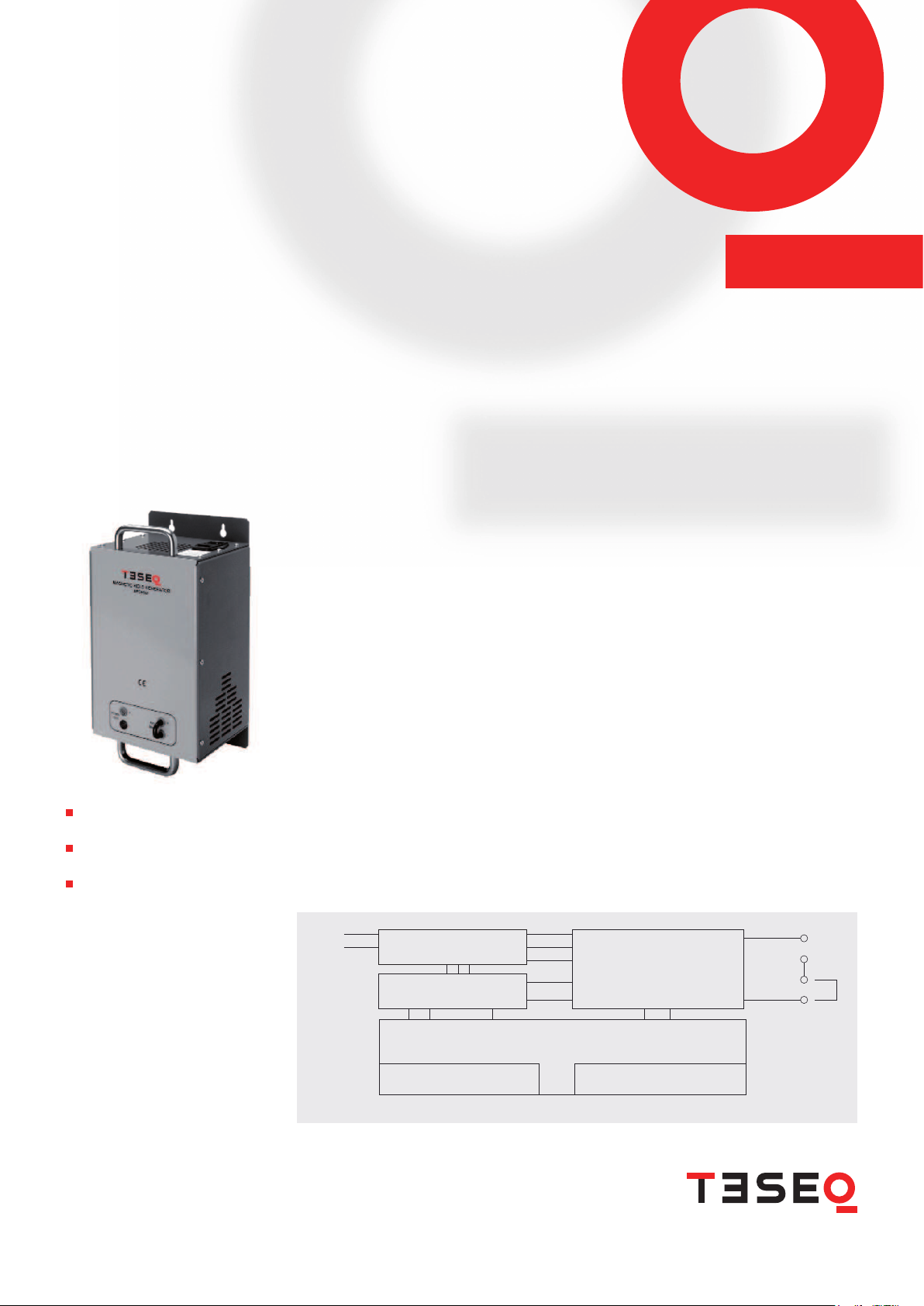
Power
line
Black
Sine wave signal generator
Power supply
Power amplier
Modula peripheral controller PC 6501
50Hz
60Hz
Amplitude Range low/high
Plug X1 – System cable IN
25 way sub D - male
Red
Plug X2 – System cable OUT
25 way sub D - female
System cable to Modula system Termination with Modula interlock plug
Electronic devices containing components sensitive to magnetic elds need to be tested for immunity
to electromagnetic elds. Product standards de ne the applicability of such tests and specify the eld
strength. The basic standard IEC/EN 61000-4-8 describes the test methods for magnetic elds with
powerline frequencies.
The MFO 6502 is an auxiliary device for the Modula system and provides fully automatic power line
magnetic eld tests. It is connected via the system cable to the Modula system and is fully embedded
in the con guration management, the software control and the report mechanism.
The unit consists of a programmable low impedance power ampli er boxed in a sturdy aluminum housing
tted with convenient handles. It is used to drive magnetic loop antennas type INA 702 or INA 701. Other
magnetic loops with similar speci cations and known antenna factors may be used instead.
The resulting magnetic elds depend on the antenna used. 50 and 60 Hz magnetic elds up to 40 A/m
can be generated with the antenna INA 702.
The use of a power ampli er provides the advantage of reduced size and weight and allows for 50 and
60 Hz testing irrespective of the local power network.
All the required parameters to run an automatically controlled test can be set either by the Modula
handheld controller or by means of WinModula software from PC. Once the individual antenna factor
has been entered, the system calculates the necessary drive parameters to achieve the set eld strength
at the antenna loop.
The WinModula test library has been extended to cover the IEC/EN 61000 -4-8 tests as well as the power
frequency magnetic eld tests speci ed by the generic standards and a considerable number of product
standards.
Block diagram
Integrated function unit to
Modula system
Magnetic field test with 50 or 60
Hz up to 40 A/m
Complies with IEC/EN 61000-4-8
AUTOMATIC POWER LINE FREQUENCY
MAGNETIC FIELD
MFO 6502
Page 2

With magnetic antenna loop INA 701:
Field strength, low range: 0.08 to 0.4 A /m
(80 to 400 mA drive current)
High range: 0.2 to 3.6 A /m
(200 mA to 4.1 A drive current)
With magnetic antenna loop INA 702:
Field strength, low range: 0.8 to 4 A/m
(80 to 400 mA drive current)
High range: 2 to 40 A/m
(200 mA to 4.1 A drive current)
Total harmonic distortion (THD): <8% for levels 1 to 4, <3.5% at max. output
Test frequency: Selectable 50 and 60 Hz ±3%
Magnetic eld adjustment: Software driven
Instrument supply: Universal power supply 100 to 250 VAC, 47 to 63 Hz
Operating temperature 5 to 40°C
Overload protection: Temperature sensor
Dimensions L x W x H: 380 x 195 x 180 mm (15 x 7.7 x 7.1)
Weight: 4.2 kg (9.3 lbs) approx.
Control cable: Modula system cable, 2 m (79) (included in delivery)
Modula system requirements: Master controller revision 2 (copper interface)
Master controller rmware 1.17 or higher
MHC software, ModPDA version 2.30 or higher
WinModula version 2.30 or higher
AUTOMATIC POWER LINE FREQUENCY MAGNETIC FIELD
MFO 6502
Technical specifications
Teseq AG
Nordstrasse 11F 4542 Luterbach Sw itzer land
T + 41 32 681 40 40 F + 41 32 681 40 48
sales@teseq.com w ww.teseq.com
691-03 8A Jul 2 007
 Loading...