

Page 1
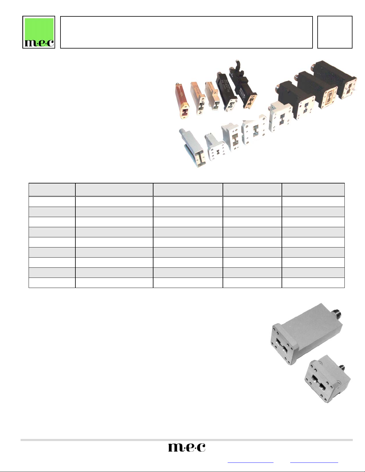
END LAUNCH ADAPTERS
RE40 SERIES
• BROAD BAND — OCTAVE OR MORE
• LOW VSWR
• HIGH POWER
DESCRIPTION
MEC state-of-the-art End Launch adapters fulfill the need
for in-line units with broadband capability. Their unique
design achieves low profile with short length, low loss and
VSWR.
Of special significance is the inherent ability of these
units to operate over a multi-octave band at high
power levels, making them ideal for EW/ECM
applications where transmission line routing space is
at a premium.
SPECIFICAITONS
MODEL
NO.
RE45 18.0 – 40.0 WRD180C24 1.5 2.0 Max
RE46 11.0 – 26.5 WRD110C24 1.4 2.0 Max
RE40 7.5 – 18.0 WRD750D24 1.3 2.75 Max
RE47
RE48 5.8 – 16.0 WRD580D24 1.3 3.0 Max
RE41 4.75 – 11.0 WRD475D24 1.25 3.5 Max
RE49 4.75 – 11.0 DR-19 1.25 3.5 Max
RE42 3.5 – 8.2 WRD350D24 1.25 4.8 Max
RE43 2.0 – 4.8 WRD200D24 1.25 6.5 Max
ORDERING INFORMATION
(1) Add the following suffixes to the model number to specify connector and power:
(a) CONNECTOR: -3 for SMA female -T for TNC female -N for type N
Female
-3M for SMA male -TM for TNC male -NM for type N male
-7 for precision 7mm -SC for SC female
-SCM for SC male
(b) POWER: -P for high power levels, namely:
SC to 8.2 GHz-800 W av.
N to 6 GHz-600 av. Derate lineraly to 300 W at 18 GHz.
TNC to 18 GHz-200 W av.
SMA to 18 GHz-50 W av.
EXAMPLE: RE43-SC-P is the model number for the WRD-200D24 Double-Ridge Waveguide to SC female
(2) Other flanges, connectors and frequency ranges available on request. Alternate tapped
(3) Single ridge waveguide is available on special request.
TYPICAL EXAMPLE: Frequency 2.6-5.2 GHz, VSWR 1.10, Length 1.30”.
1551 STREET, NORTH ANDOVER, MA 01845 • TEL (978) 685-2776 • FAX (978) 975-4363 • Website: www.microwaveeng.com • Email: sales@microwaveeng.com
coaxial connector End Launch Adapter rated at 800 W average power.
cover flange is standard.
FREQUENCY RANGE
(GHz)
6.5 – 18.0 WRD650D28 1.3 2.65 Max
MICROWAVE ENGINEERING CORPORATION
WAVEGUIDE
SIZE
VSWR
(MAX.)
RE47
Data subject to change without notice
BODY LENGTH
DATA
SHEET
No. T74B
(IN.)
RE47S
 Loading...