

Page 1
Technical Data Sheet & Configuration Guide
High Performance, Broadband
Network Analysis Solutions
ME7838A Series Vector Network Analyzers
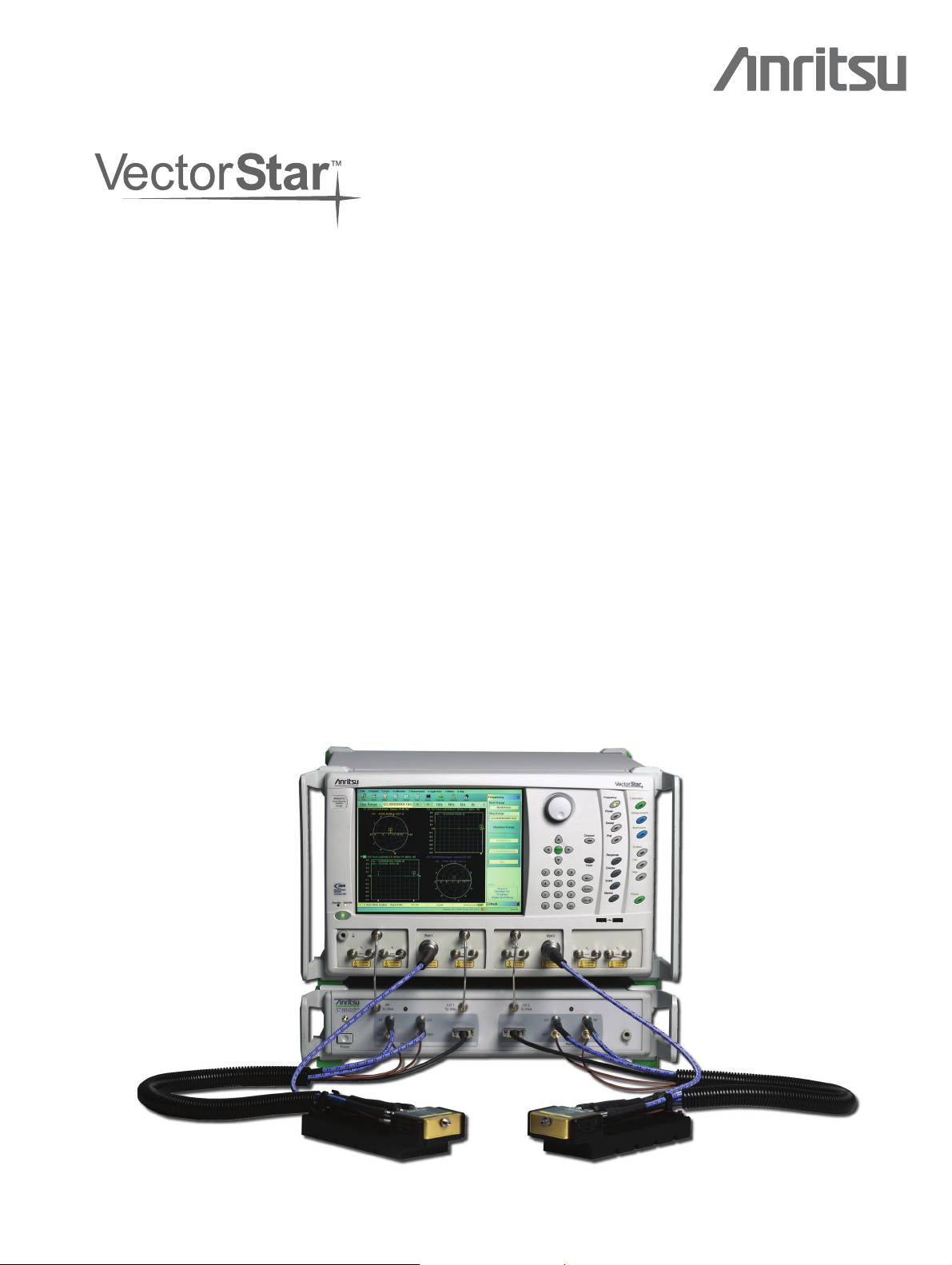
Broadband VNA System
70 kHz to 110 (125) GHz
The ME7838A broadband VNA system provides single sweep
coverage from 70 kHz to 110 GHz and is operational from 40 kHz to
125 GHz. It consists of the following items:
• MS4
647A VectorStar VNA, 70 kHz to 70 GHz with Option 007,
Option 070, and Option 080/081
• 3739B Broadban
• 3743A Millimeter
d Millimeter-Wave Test Set and Interface Cables
-Wave Modules, 2 each
Broadband/Millimeter-Wave System Options
• MS4640A-002, Time Domain
640A-041, Noise Figure
• MS4
640A-051, External VNA Direct Access Loops
• MS4
• MS4640A-061, Active Measurement Suite, with 2 Attenuators
640A-062, Active Measurement Suite, with 4 Attenuators
• MS4
Millimeter Waveguide VNA System
50 GHz to 750 GHz (1.1 THz)
The ME7838A Millimeter-Wave configuratio
output from 50 GHz to 750 GHz (1.1 THz) in waveguide bands. The
system can
only as a waveguide system. It consists of the following items:
• MS46
• 3739B Broadband
• Millimeter-Wave modules, 2 each
• SC8215 and SC7287 Kelvin Bias Tees
• 3744A-Rx, 3
for Noise Figure and mm-Wave Antenna Measurements
• 3744A-EE,
• 3744A-EW, 65 to 110 GHz WR-10 Waveguide Module
extend the broadband system or be configured to operate
4xA VectorStar VNA, with Option 007 and Option 082/083
/Millimeter-Wave Test Set and Interface Cables
0 to 125 GHz mm-Wave Receiver
56 to 95 GHz WR-12 Waveguide Module
n provides waveguide
VectorStar ME7838A Broadband System
Page 2

Table of Contents VectorStar ME7838A BB/mm-Wave VNA
Description Page
1. Definitions. . . . . . . . . . . . . . . . . . . . . . . . . . . . . . . . . . . . . . . . . . . . . . . . . . . . . . . . . . . . . . 2
2. Specifications for Broadband Configuration . . . . . . . . . . . . . . . . . . . . . . . . . . . . . . . . . . . . . . . 3
3. Specifications for Waveguide Band Configuration . . . . . . . . . . . . . . . . . . . . . . . . . . . . . . . . . . 12
4. VectorStar ME7838A Waveguide Bands from 50 GHz to 750 GHz (1.1 THz). . . . . . . . . . . . . . . . 21
5. Standard Capabilities for All Configurations . . . . . . . . . . . . . . . . . . . . . . . . . . . . . . . . . . . . . . 25
6. Mechanical and Environmental. . . . . . . . . . . . . . . . . . . . . . . . . . . . . . . . . . . . . . . . . . . . . . . 25
7. Calibration and Correction Capabilities . . . . . . . . . . . . . . . . . . . . . . . . . . . . . . . . . . . . . . . . . 26
8. Mechanical Calibration/Verification Kits. . . . . . . . . . . . . . . . . . . . . . . . . . . . . . . . . . . . . . . . . 27
9. Test Port Cables. . . . . . . . . . . . . . . . . . . . . . . . . . . . . . . . . . . . . . . . . . . . . . . . . . . . . . . . . 28
10. Precision Adapters, Attenuators, and Other Components. . . . . . . . . . . . . . . . . . . . . . . . . . . . 28
11. Warranty. . . . . . . . . . . . . . . . . . . . . . . . . . . . . . . . . . . . . . . . . . . . . . . . . . . . . . . . . . . . . 29
12. Ordering Information . . . . . . . . . . . . . . . . . . . . . . . . . . . . . . . . . . . . . . . . . . . . . . . . . . . . 29
1. Definitions
Temperature Range
Error-Corrected Specifications
Typical P e r f o r m a n c e
Discrete Spurious Responses
Internal Reference Signal
Characteristic Performance
Recommended Calibration Cycle
Interpolation Mode
Specifications Subject to Change
Warm-Up Time
User Cables
Below 300 kHz
All specifications and characteristics apply under the following conditions, unless otherwise stated:
After 90 minutes of warm-up time, where the instrument is left in the ON state.
Over the 25 °C ± 5 °C temperature range.
For error-corrected specifications, over 23 °C ± 3 °C, with < 1 °C variation from calibration temperature.
For error-corrected specifications are warranted and include guard bands, unless otherwise stated.
"Typical" specifications describe expected, but not warranted, performance based on sample testing.
Typical performance indicates the measured performance of an average unit and do not guarantee the
performance of any individual product. "Typical" specifications do not account for measurement uncertainty
and are shown in parenthesis, such as (-102 dB), or noted as Typical.
Specifications do not include effects of any user cables attached to the instrument.
Specifications may exclude discrete spurious responses.
All specifications apply with internal 10 MHz Crystal Oscillator Reference Signal.
Characteristic performance indicates a performance designed-in and verified during the design phase. It
does include guard-bands and is not covered by the product warranty.
All uncertainties below 300 kHz are typical.
12 months
All specifications are with Interpolation Mode Off.
All specifications subject to change without notice. For the most current data sheet, please visit the Anritsu
web site at
www.anritsu.com
.
2 PN: 11410-00593 Rev. D ME7838A BB/mm-Wave VNA TDS
Page 3

VectorStar ME7838A BB/mm-Wave VNA Broadband Specifications and Performance
2. Specifications for Broadband Configuration
Broadband Specifications and Performance
2.1 ME7838A Broadband System Configuration
ME7838A Broadband Hardware Configuration
The ME7838A broadband VNA system provides single sweep coverage from 70 kHz to 110 GHz and is operational from 40 kHz to 125 GHz. It
consists of the following items:
MS4647A VectorStar VNA, 70 kHz to 70 GHz with Option 007, Option 070, and Option 080/081
VNA
Test S e t
mm-Wave Modules
3739B Broadband Test Set and interface cables
3743A Millimeter-Wave Modules, 2 each
ME7838A Broadband System Major Options
The major ME7838A broadband VNA system options are:
Option 002
Option 041
Option 051
Option 061
Option 062
Bias Tees
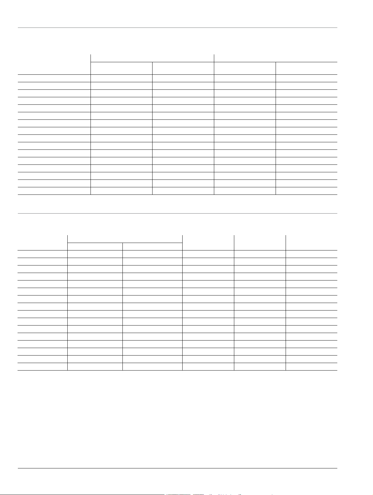
2.2 System and Receiver Dynamic Range, Noise Floor
System Dynamic Range
Noise Floor
Receiver Dynamic Range
Normalizing Measurement
System Dynamic Range (dB)
Frequency Range
70 to 300 kHz 93 90 89 86 –83 –80
0.3 to 2 MHz 103 100 103 102 –93 –90
2 to 10 MHz 115 112 115 114 –105 –102
0.01 to 2.5 GHz 120 116 121 122 –110 –109
2.5 to 24 GHz 110 105 121 121 –110 –108
24 to 54 GHz 110 107 124 123 –114 –113
54 to 60 GHz 108 108 122 122 –112 –112
60 to 67 GHz 108 108 117 117 –107 –107
67 to 80 GHz 108 108 120 120 –110 –110
80 to 85 GHz 107 107 123 123 –113 –113
85 to 90 GHz 107 107 121 121 –111 –111
90 to 95 GHz 109 109 121 121 –111 –111
95 to 105 GHz 107 107 117 117 –107 –107
105 to 110 GHz 109 109 122 122 –112 –112
110 to 120 GHz
120 to 125 GHz
a. Excludes localized spurious responses and crosstalk.
b. 110 to 125 GHz frequency range is available as operational.
b
b
ME7838A
107 107 115 115 –110 –110
104 104 112 112 –107 –107
MS4640A-002, Time Domain
MS4640A-041, Noise Figure
MS4647A-051, External VNA Direct Access Loops
MS4647A-061, Active Measurement Suite, with 2 Attenuators
MS4647A-062, Active Measurement Suite, with 4 Attenuators
SC8215 and SC7287 Kelvin Bias Tees
(Excludes localized spurious responses and crosstalk)
System dynamic range is measured as the difference between maximum port power and the RMS noise
floor in a 10 Hz bandwidth and no averaging (ports terminated).
Noise floor is calculated as the difference between maximum rated port power and system dynamic range.
Receiver Dynamic Range is calculated as the difference between the receiver compression level and the
noise floor at Ports 1 or 2.
Normalizing measurement made with a through line connection, with its effects compensated for. The
cables between the VNA and the 3743A modules are assumed to be the 806-206 1.85 mm cable (61 cm,
24 in long) or the 806-209 1.85 mm cable (91 cm, 36 in long). All figures are typical.
a
Receiver Dynamic Range (dB)a Noise Floor (dBm)a
ME7838A
Option 062 ME7838A
ME7838A
Option 062 ME7838A
ME7838A
Option 062
ME7838A BB/mm-Wave VNA TDS PN: 11410-00593 Rev. D 3
Page 4
Broadband Specifications and Performance VectorStar ME7838A BB/mm-Wave VNA
2.3 Test Port Power, Receiver Compression
Port power control is provided by the base VNA for frequencies below 54 GHz, and by the 3743A mm-Wave module for frequencies greater than
54 GHz. Receiver compression point is defined as the port power level beyond which the response may be compressed more than 0.2 dB re
to normalization level. 10 Hz IF bandwidth used to remove trace noise effects. All typical.
Port Power Receiver Compression
Frequency Range
70 to 300 kHz 10 10 6 6
0.3 to 2 MHz 10 10 10 12
2 to 10 MHz 10 10 10 12
0.01 to 2.5 GHz 10 7 11 13
2.5 to 24 GHz 0 –3 11 13
24 to 54 GHz –4 –6 10 10
54 to 60 GHz –4 –4 10 10
60 to 67 GHz 1 1 10 10
67 to 80 GHz –2 –2 10 10
80 to 85 GHz –6 –6 10 10
85 to 90 GHz –4 –4 10 10
90 to 95 GHz –2 –2 10 10
95 to 105 GHz 0 0 10 10
105 to 110 GHz –3 –3 10 10
110 to 120 GHz
120 to 125 GHz
a. Using the 806-206 1.85 mm (61 cm, 24 in long) test port cables or the 806-209 1.85 mm (91 cm, 36 in long) test port cables between the
VNA and the 3743A mm-Wave modules.
b. 110 to 125 GHz frequency range is available as operational.
b
b
Max Power
ME7838A
–3 –3 5 5
–3 –3 5 5
Max Power
ME7838A Option 062
Compression
ME7838A
ME7838A Option 062
a
Compression
Power Range, Accuracy, Linearity, and Resolution
Accuracy is defined at –10 dBm or max rated power, whichever is lower. Linearity is defined as the incremental error between the accuracy test
power level and 5 dB below. Typical.
Range (dB)
Frequency
70 to 300 kHz -25 to +10 -85 to +10 ±1.5 ±1.5 0.01
0.3 to 2 MHz -25 to +10 -85 to +10 ±1.5 ±1.5 0.01
2 to 10 MHz -25 to +10 -85 to +10 ±1.5 ±1.5 0.01
.01 to 2.5 GHz -25 to +10 -85 to +8 ±1.0 ±1.0 0.01
2.5 to 24 GHz -25 to 0 -85 to -3 ±1.0 ±1.0 0.01
24 to 54 GHz -30 to -4 -90 to -6 ±1.5 ±1.0 0.01
54 to 60 GHz -55 to -4 -55 to -4 ±2.0 ±1.5 0.01
60 to 67 GHz -55 to +1 -55 to +1 ±2.0 ±1.5 0.01
67 to 80 GHz -55 to -2 -55 to -2 ±2.0 ±1.5 0.01
80 to 85 GHz -55 to -6 -55 to -6 ±2.0 ±1.5 0.01
85 to 90 GHz -55 to -4 -55 to -4 ±2.0 ±1.5 0.01
90 to 95 GHz -55 to -2 -55 to -2 ±2.0 ±1.5 0.01
95 to 105 GHz -55 to 0 -55 to 0 ±3.0 ±2.0 0.01
105 to 110 GHz -50 to -3 -55 to -3 ±3.0 ±2.0 0.01
110 to 120 GHz
120 to 125 GHz
a. 110 to 125 GHz frequency range is available as operational.
a
a
-40 to -3 -40 to -3 ±4.0 ±3.0 0.01
-40 to -3 -40 to -3 ±4.0 ±3.0 0.01
Accuracy
B)
(d
Linearity
(dB)
Resolution
lative
(dB)ME7838A ME7838A Option 062
4 PN: 11410-00593 Rev. D ME7838A BB/mm-Wave VNA TDS
Page 5
VectorStar ME7838A BB/mm-Wave VNA Broadband Specifications and Performance
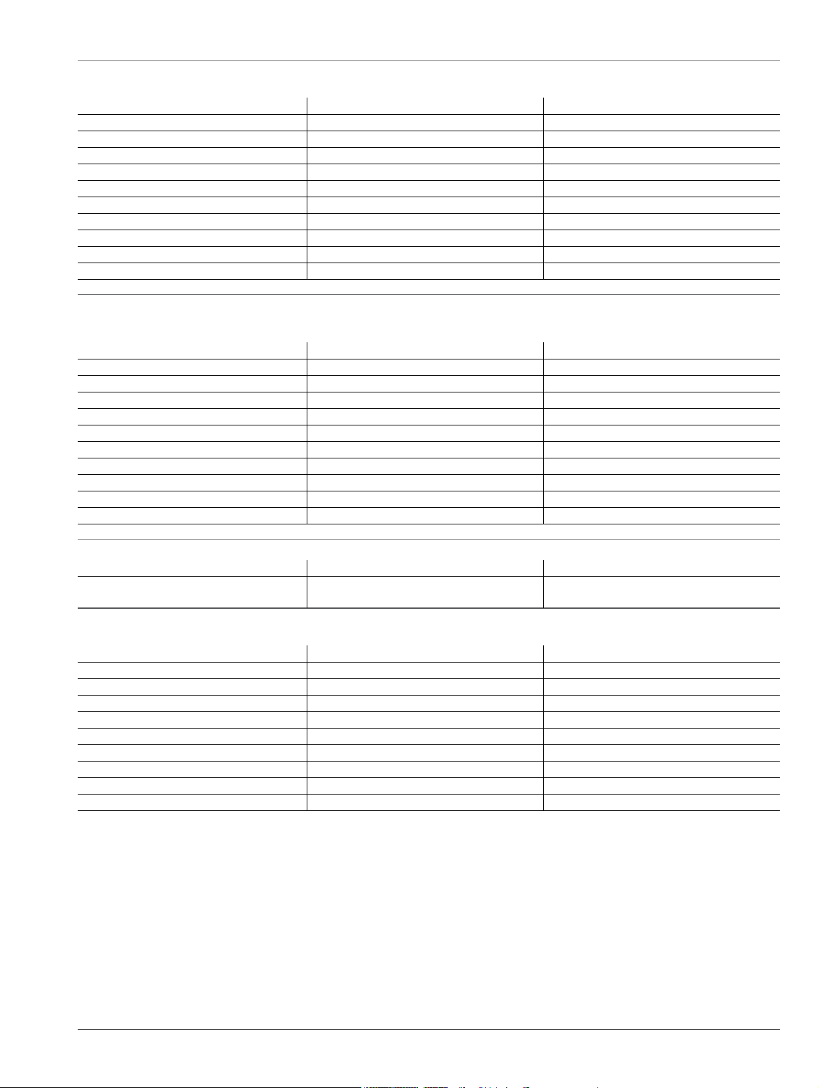
2.4 High Level Noise
Noise measured at 1 kHz IF bandwidth, at maximum power or compression limit (whichever is less), with through transmission. RMS. Typical.
Frequency (GHz) Magnitude (dB) Phase (deg.)
70 to 500 kHz < 0.04 < 0.4
0.5 to 2 MHz < 0.005 < 0.05
2 to 10 MHz < 0.005 < 0.05
0.01 to 2.5 < 0.005 < 0.05
2.5 to 24 < 0.006 < 0.06
24 to 54 < 0.005 < 0.06
54 to 80 < 0.005 < 0.06
80 to 110 < 0.008 < 0.09
110 to 120
120 to 125
a. 110 to 125 GHz frequency range is available as operational.
2.5 Stability
Ratioed measurement at maximum leveled power and with nominally a full reflect or a stable thru over the normal specified temperature range.
Typic al .
Frequency (GHz) Magnitude (dB/°C) Phase (deg./°C)
70 to 300 kHz < 0.04 < 0.4
0.3 to 2 MHz < 0.04 < 0.4
2 to 10 MHz < 0.04 < 0.4
0.01 to 2.5 < 0.03 < 0.3
2.5 to 24 < 0.03 < 0.3
24 to 54 < 0.03 < 0.4
54 to 80 < 0.03 < 0.4
80 to 110 < 0.03 < 0.5
110 to 120
120 to 125
a. 110 to 125 GHz frequency range is available as operational.
2.6 Frequency Resolution, Accuracy, and Stability
Resolution Accuracy Stability
2.7 Uncorrected (Raw) Port Characteristics
Typical performance with either ME7838A or ME7838A with Option 062.
Frequency (GHz) Directivity (dB) Port Match (dB)
<10 MHz 10
0.01 to 2.5 9
2.5 to 30 5
30 to 40 5
40 to 54 10 5
54 to 80 10 10
80 to 110 5 7
110 to 120
120 to 125
a. Raw directivity is degraded below 300 kHz, 2.2 to 2.5 GHz and in narrow bands within 10 to 34 GHz.
b. 110 to 125 GHz frequency range is available as operational.
a
a
< 0.025 < 0.30
a
a
< 0.1 < 1.0
1 Hz
b
b
5 7
< 0.010 < 0.20
< 0.06 < 1.0
–7
± 5 x 10
Hz/Hz
(at time of calibration)
a
8
a
10
a
12
a
5
< 5 x 10⁻⁹/°C over 0 °C to 50 °C temperature
< 1 x 10
5 7
–9
/day aging, instrument on
ME7838A BB/mm-Wave VNA TDS PN: 11410-00593 Rev. D 5
Page 6
Broadband Specifications and Performance VectorStar ME7838A BB/mm-Wave VNA
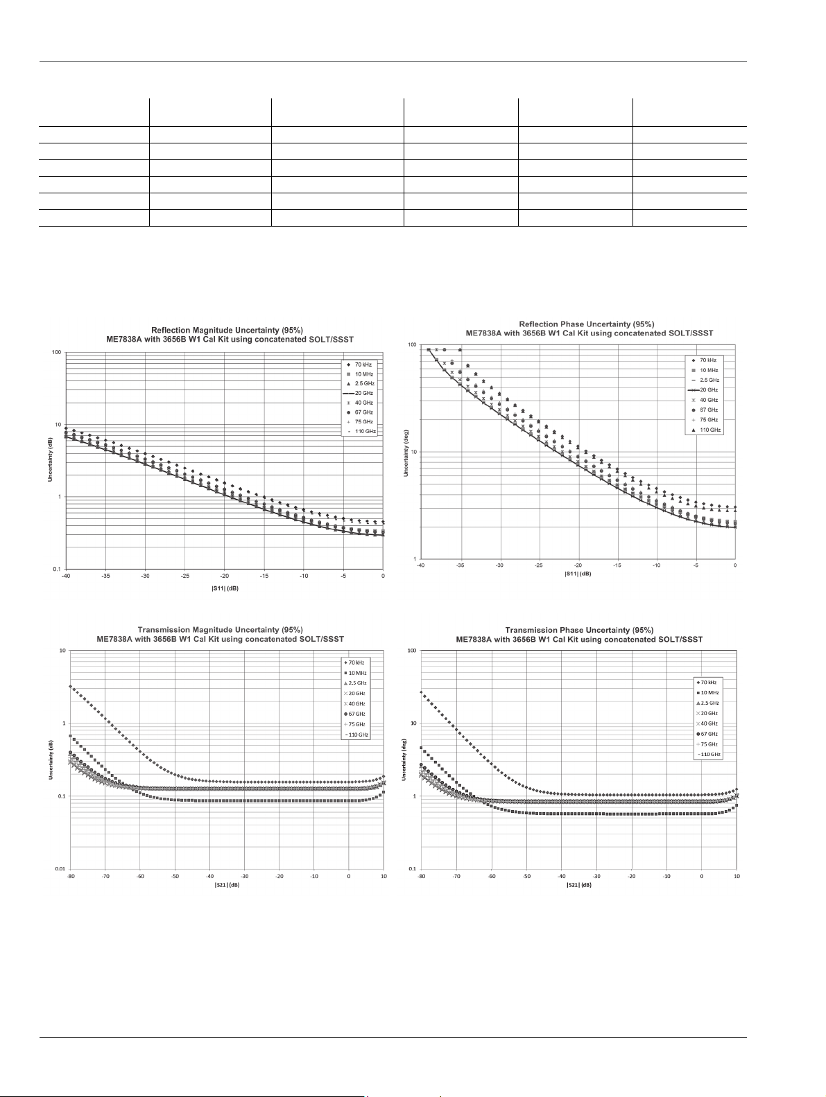
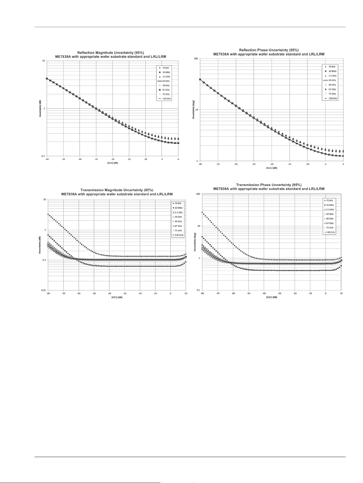
2.8 Corrected System Performance and Uncertainties – SOLT/SSST
With 12-term concatenated SOLT and Triple Offset Short Calibration (SSST), using the 3656B W1 Calibration Kit. Typical.
Frequency (GHz) Directivity (dB) Source Match (dB) Load Match (dB)
70 kHz to 10 MHz 36 36 36 ± 0.1 ± 0.1
0.01 to 2.5 40 41 40 ± 0.05 ± 0.03
2.5 to 20 40 41 40 ± 0.05 ± 0.05
20 to 67 38 41 38 ± 0.05 ± 0.07
67 to 95 37 42 37 ± 0.05 ± 0.07
95 to 110 35 35 35 ± 0.05 ± 0.07
Reflection
Tr
acking (dB)
Measurement Uncertainties – SOLT/SSST
The graphs give measurement uncertainties after the above calibration. The errors are worst case contribution of residual directivity, load and
source match, frequency response and isolation, network analyzer dynamic accuracy, and connector repeatability while noise effects are added
on an RSS basis. 10 Hz IF Bandwidth is used. For transmission uncertainties, it is assumed that s11 = s22 = 0. For reflection uncertainties, it is
assumed that s21 = s12 = 0. For other conditions, please use our free Exact Uncertainty calculator software, downloadable from the Anritsu web
site at www.anritsu.com.
Transmission
Tracking (dB)
6 PN: 11410-00593 Rev. D ME7838A BB/mm-Wave VNA TDS
Page 7
VectorStar ME7838A BB/mm-Wave VNA Broadband Specifications and Performance
2.9 Corrected System Performance and Uncertainties – LRL/LRM
With 12 term LRL/LRM calibration using on-wafer substrate standards. Typical. Based on a typical vendor supplied impedance standard substrate.
ME7838A BB/mm-Wave VNA TDS PN: 11410-00593 Rev. D 7
Page 8
Broadband Specifications and Performance VectorStar ME7838A BB/mm-Wave VNA
2.10 Measurement Time
Measurement times include sweep time, retrace time, and band-switching time. Typical.
Measurement Time (ms)
Full Band, 70 kHz to 110 GHz, Display ON, and ALC ON.
Measurement Time (ms)
Calibration IFBW
1 MHz 80 100 350 700
30 kHz 90 160 600 1500
1-port calibration
2-port calibration
a. Measurement times are for ME7838A Broadband and ME7838A Millimeter-Wave Systems.
10 kHz 110 240 1100 2600
1 kHz 470 1600 10,000 25,000
10 Hz 47,000 160,000 1,000,000 2,500,000
1 MHz 160 200 700 1400
30 kHz 180 320 1200 3000
10 kHz 220 480 2200 5200
1 kHz 940 3200 20,000 50,000
10 Hz 94,000 320,000 2,000,000 5,000,000
401 Points 1,601 Points 10,001 Points 25,000 Points
Measurement Time (ms) vs. System Dynamic Range (dB)
Full Band, Display ON, and ALC ON.
Calibration
Uncorrected or
t calibration
1-por
2-port calibration
401 Points
M
easurement Time
110
470
220
940
Achieved System Dynamic
Range (Opt 062 at 54 GHz) IFBW and Averaging Used
77
87
77
87
a
10 kHz/no avg
1 kHz/no avg
10 kHz/no avg
o avg
1 kHz/n
8 PN: 11410-00593 Rev. D ME7838A BB/mm-Wave VNA TDS
Page 9

20-40 GHz
5 dBm
RF
5-10 GHz
5 dBm
LO1
5-10 GHz
5 dBm
LO2
VectorStar MS4647A VNA with Option 08x
Model 3739B Broadband Test Set
RF
W1 Test Ports
LO1 LO2
3743A mm-Wave
Module
3743A mm-Wave
Module
LO to RCVR
5-10 GHz
ALC Pwr & Control
ALC Pwr & Control
Ref IF
RF to Multipliers
20-40 GHz
Test IF
TP1 TP2
P1 RF Out 70 kHz to 54 GHz
P2 RF Out 70 kHz to 54 GHz
LO to RCVR
5-10 GHz
EXT ALC Input to VNA
Four External IF Inputs to VNA
External I/O from VNA
Analog Output from VNA
Ref IF
RF to Multipliers
20-40 GHz
Test IF
VectorStar ME7838A BB/mm-Wave VNA Broadband Specifications and Performance
2.11 Block Diagram – ME7838A Broadband VNA System
Broadband Configuration Block Diagram
2.12 SC8215 and SC7287 Kelvin Bias Tees
Provides Sense and Force SMC connections close to the mm-Wave module to minimize the IR drops associated with the impedances between the
bias tee and the DUT.
Part Number Description Voltage Current
SC8215
SC7287 The SC7287 is a bias tee providing DC bias from 100
Tri-Axial Output SMUs For applications requiring Source Measure
The SC8215 is a bias tee providing DC bias from 70 kHz
GHz.
to 110
to 110 GHz.
MHz
available, with the inner-shield isolated from ground at the bias tee SMC end, to float at the SMU guard potential.
Check the accessories list for
ordering information on page 30.
Units (SMU) with tri-axial outputs, a tri-axial (male) to SMC (male) cable is
Max Voltage: 16 VDC Max Current: 100 mA
Max Voltage: 50 VDC Max Current: 500 mA
ME7838A BB/mm-Wave VNA TDS PN: 11410-00593 Rev. D 9
Page 10
Broadband Specifications and Performance VectorStar ME7838A BB/mm-Wave VNA
10 GHz 110 GHz
Pow er M ete r vs a1/1 Receive r
–10.5
–10.4
–10.3
–10.2
–10.1
–10
–9.9
–9.8
–9.7
–9.6
–9.5
0 10 20 29 39 48 58 67 76 86 95 105 114 125
Frequency (GHz)
dBm
|a1 /1 |
Power Meter
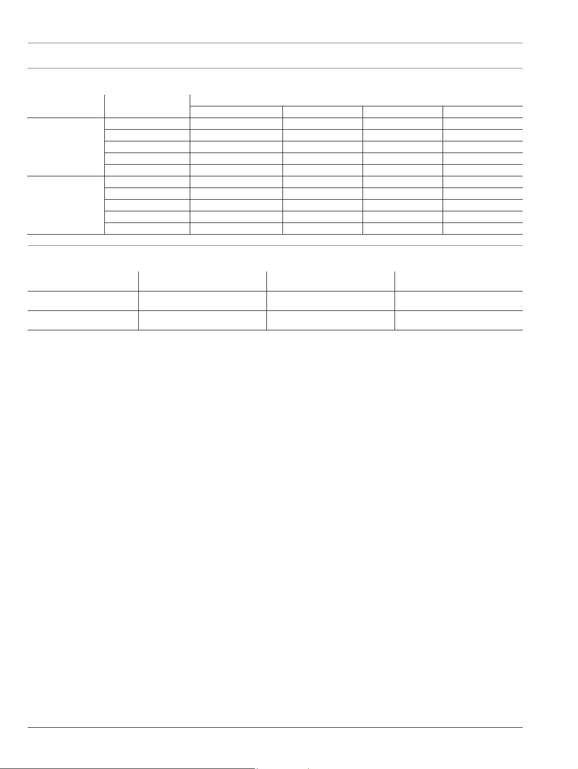
2.13 Measurement Examples
The following figures are measurement examples of the ME7838A Broadband system performance.
Dynamic range of ME7838A system at the W1 1 mm coaxial test port from 70 kHz to 125 GHz.
An example of power measurement agreement: power sensor vs. ME7838A a1 reference receiver.
Power sweep range at 77 GHz. By using detection and power control
inside the 3743A millimeter-wave module; improved accuracy,
linearity and range can be achieved.
10 PN: 11410-00593 Rev. D ME7838A BB/mm-Wave VNA TDS
Power sweep range at 94 GHz demonstrating
greater than 50 dB of control.
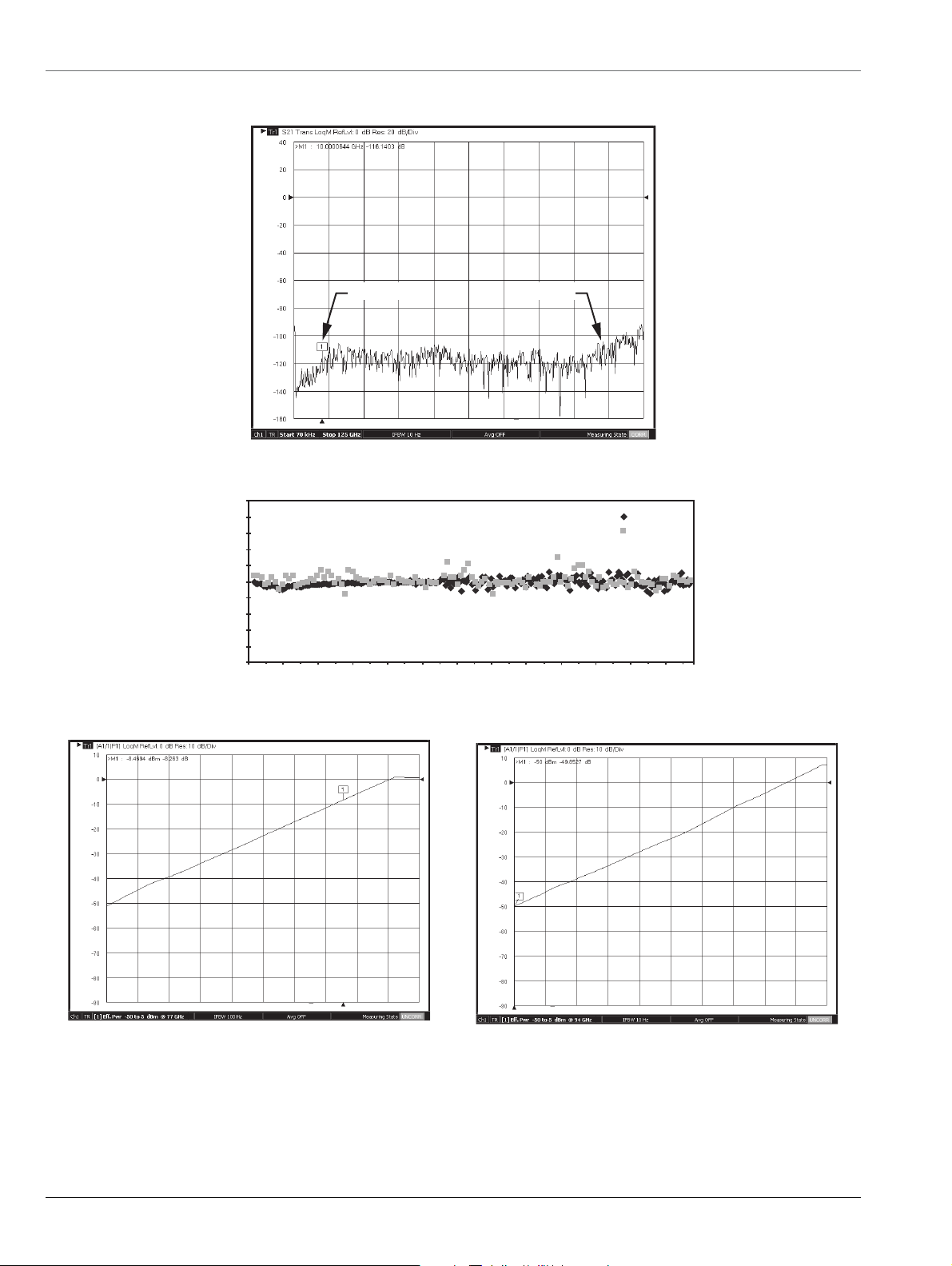
Page 11
VectorStar ME7838A BB/mm-Wave VNA Broadband Specifications and Performance
Example 24 hour vector reflect stability (high reflect)
Vector delta (dB)
–100
–90
–80
–70
–60
–50
–40
–30
–20
–10
0
0 20 40 60 80 100 125
Frequency (GHz)
110
Thru Line Transmission (24 Hours)
–0.15
–0.05
0.05
0.15
0 25 50 75 100 125
Frequency (GHz)
dB
Deg
–1.5
–0.5
0.5
1.5
mag
phase
110
Thru Line Match (24 Hours)
–80
–60
–40
–20
0
0 25 50 75 100 125
Frequency (GHz)
|Delta Refl Coeff| (dB)
24 hour high reflect stability in vector delta format
Thru line transmission stability up to 125 GHz
ME7838A BB/mm-Wave VNA TDS PN: 11410-00593 Rev. D 11
Example of vector delta thru line match after 24 hours
o
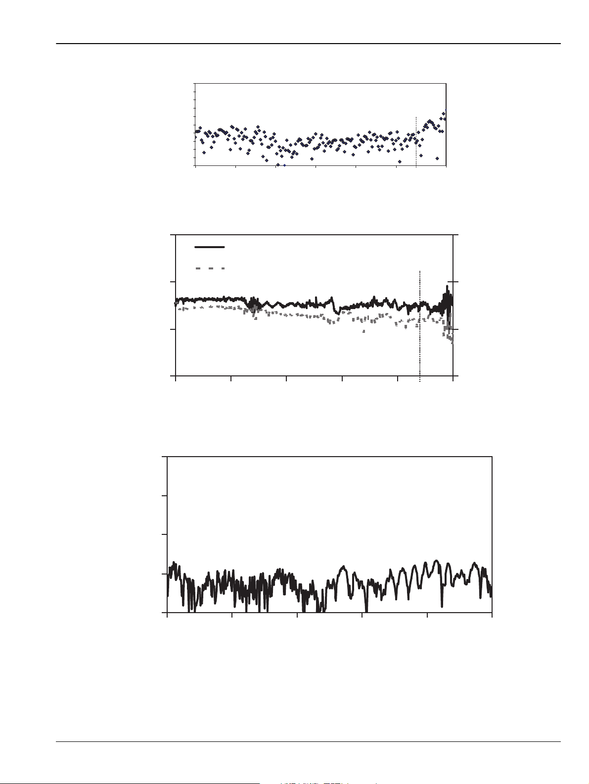
Page 12

Waveguide Band Specifications and Performance VectorStar ME7838A BB/mm-Wave VNA
Power deviations relative to 25 °C; –10 dBm port
–2
0
2
55 75 95 125
Frequency (GHz)
50 °C 70 °C
0 °C –20 °C
dB
Power & phase deviations relative to 3 °C Change; -10 dBm port
–0.2
0
0.2
54 74 94
110
Frequency (GHz)
dB
–2
0
2
mag
phase
Deg
Power deviation with respect to wide temperature variation
Example of thru line stability of mag and phase reflective of a 3 °C change
3. Specifications for Waveguide Band Configuration
3.1 ME7838A Millimeter-Wave VNA, Waveguide Bands
Three configurations are available for waveguide band operation for E and W bands when using the ME7838A system.
• Firs
adapters.
• Seco
waveguide bands and are operational using the MS4644A, MS4645A, or MS4647A VectorStar (with options 08x and 007) and the 3739B
broadband/millimeter-wave test set.
• Th
3739B test set. For millimeter bands above 110 GHz either the OML or VDI modules may be used.
12 PN: 11410-00593 Rev. D ME7838A BB/mm-Wave VNA TDS
t, the Anritsu 3743A Broadband Millimeter-Wave (mm-Wave) module can be adapted to waveguide measurements using waveguide
nd, the Anritsu 3744A-EE or 3744A-EW millimeter-wave module can be used. These version modules operate in the extended E and W
e third configuration option is to use external millimeter-wave modules with any model VectorStar (with options 08x and 007) and the
Waveguide Band Specifications and Performance
Page 13

VectorStar ME7838A BB/mm-Wave VNA Waveguide Band Specifications and Performance
3.2 E and W Band Operation Using the 3743A, 3744A-EE, or 3744A-EW mm-Wave Module
3743A Millimeter-Wave Modules
3744A-EE/3744A-EW Millimeter-Wave Module with Waveguide Adapter
The 3743A Broadband mm-Wave module can be adapted to a waveguide band output by adding an available waveguide band adapter and
mounting flange. VectorStar menus automatically configure the system frequencies incorporating the 3743A module for banded operation. Using
the 3743A modules provides the opportunity to sweep frequencies for broadband applications and quickly convert to waveguide configurations for
banded measurements. The advantages of small compact modules with excellent RF performance and power range control can therefore be
realized in both broadband and waveguide configurations when using the 3743A mm-Wave module. For systems where only waveguide band
operation is required, the 3744A-EE or 3744A-EW mm-Wave module can be used.
The 3744A-EE or 3744A-EW mm-Wave module operates from 54 GHz to 110 GHz. The band supported is determined by the waveguide adapter
onnected to the 1 mm test port output of the 3744A-EE/EW module:
c
44A-EE configures the module for Extended E Band
• 37
44A-EW configures for Extended W Band
• 37
The RF input port of the 3744A-EE or 3744A-EW module is restricted be
1 mm test port. Thus, the waveguide adapter can be remo
can be biased through the RF input port.
Band Frequency Range Waveguide Flange Transmission/Reflection Module
Ext-E 56 to 94 GHz
Ext-W 65 to 110 GHz WR-10 3744A-EW
a. Operational to 95 GHz.
ved for on-wafer applications from 54 GHz to 110 GHz operation and the on-wafer DUT
a
low 54 GHz, however, the RF input port retains a DC connection to the
WR-12 3744A-EE
ME7838A BB/mm-Wave VNA TDS PN: 11410-00593 Rev. D 13
Page 14

Waveguide Band Specifications and Performance VectorStar ME7838A BB/mm-Wave VNA
3.3 Port Power, Noise Floor, Dynamic Range – 3744A-EE/3744A-EW mm-Wave Modules
System dynamic range is defined as the ratio of the source power to the noise floor.
Maximum Receiver Power is defined as the 0.2 dB compressio
Receiver dynamic range is defined as the ratio of maximum receive power to the noise floor.
Noise Floor measurements are RMS, are made with no average in a 10 Hz
All figures are typical.
3744A-EE Extended-E Band (WR-12) Waveguide
Frequency Range
(GHz)
56 to 60 -5 11 -111 106 122
60 to 67 0 11 -106 106 117
67 to 80 -3 11 -109 106 120
80 to 85 -7 11 -112 115 123
85 to 90 -5 11 -110 105 120
90 to 94
a. Operational to 95 GHz.
a
Source Power
(dBm)
-2 12 -105 103 117
Max. Receive Power
(0.2 dB comp. pt.) (dBm)
3744A-EW Extended-W Band (WR-10) Waveguide
Frequency Range
(GHz)
65 to 67 0 11 -106 106 117
67 to 80 -3 11 -109 106 120
80 to 85 -7 11 -112 115 123
85 to 90 -5 11 -110 105 120
90 to 105 -2 12 -105 103 117
105 to 110 -7 12 -110 103 122
Source Power
(dBm)
Max. Receive Power
(0.2 dB comp. pt.) (dBm)
Power Range, Accuracy, Linearity, and Resolution
Accuracy is defined at –10 dBm or max rated power, whichever is lower. Linearity is defined as the incremental error between the accuracy test
power level and 5 dB below. Typical.
Frequency
(GHz)
54 to 60 –55 to –4 –55 to –4 ± 2.0 ± 1.5 0.01
60 to 67 –55 to 1 –55 to 1 ± 2.0 ± 1.5 0.01
67 to 80 –55 to –2 –55 to –2 ± 2.0 ± 1.5 0.01
80 to 85 –55 to –6 –55 to –6 ± 2.0 ± 1.5 0.01
85 to 90 –55 to –4 –55 to –4 ± 2.0 ± 1.5 0.01
90 to 105 –55 to 0 –55 to 0 ± 3.0 ± 2.0 0.01
105 to 110 –50 to –5 –50 to –5 ± 3.0 ± 2.0 0.01
110 to 120
120 to 125
a. 110 to 125 GHz frequency range is available as operational.
Alternatively, the V, E and W bands can be supported using external
from Anritsu. For further description and specifications please refer to the VectorStar ME7828A Technical Data Sheet – 11410-00452 available at
www.anritsu.com.
a
a
–40 to –12 –40 to –12 ± 4.0 ± 3.0 0.01
–40 to –15 –40 to –15 ± 4.0 ± 3.0 0.01
Range (dBm)
n point of the receiver at the waveguide port.
IF bandwidth, and include an isolation calibration.
Noise Floor
(dBm)
Noise Floor
(dBm)
Accuracy
B)
(d
millimeter-wave modules such as the 3740/41A series modules available
System Dynamic
Range (dB)
System Dynamic
Range (dB)
Linearity
(dB)
Receiver Dynamic
Range (dB)
Receiver Dynamic
Range (dB)
Resolution
(dB)ME7838A ME7838A Option 062
14 PN: 11410-00593 Rev. D ME7838A BB/mm-Wave VNA TDS
Page 15

VectorStar ME7838A BB/mm-Wave VNA Waveguide Band Specifications and Performance
0.1
1
10
-40 -30 -20 -10 0
magnitude uncertainty (dB)
|S11| (dB)
Extended-E Band Reflection Magnitude Uncertainties - SSLT
56 GHz
60 GHz
77 GHz
90 GHz
94 GHz
1
10
100
-40 -30 -20 -10 0
phase uncertainty (deg.)
|S11| (dB)
Extended-E Band Reflection Phase Uncertainties - SSLT
56 GHz
60 GHz
77 GHz
90 GHz
94 GHz
0.01
0.1
1
-80 -60 -40 -20 0
magnitude uncertainty (dB)
|S21| (dB)
Extended-E Band Transmission Magnitude Uncertainties - SSLT
56 GHz
60 GHz
77 GHz
90 GHz
94 GHz
0.1
1
10
-80 -60 -40 -20 0
phase uncertainty (deg.)
|S21| (dB)
Extended-E Band Transmission Phase Uncertainties - SSLT
56 GHz
60 GHz
77 GHz
90 GHz
94 GHz
3.4 Corrected System Performance/Uncertainties – 3744A-EE/3744A-EW mm-Wave Modules
With 12-term Offset Short Sliding Load or LRL calibrations, using high precision waveguide sections and standards from the appropriate
calibration kit.
3744A-EE Extended-E Band (WR-12) Waveguide – 56 GHz to 94 GHz
Calibration
Type
Offset Short > 44 > 33 > 44 ± 0.080 ± 0.100
LRL > 44 > 43 > 44 ± 0.006 ± 0.006
3744A-EW Extended-W Band (WR-10) Waveguide – 65 GHz to 110 GHz
Calibration
Type
Offset Short > 40 > 30 > 46 ± 0.080 ± 0.100
LRL > 40 > 40 > 46 ± 0.006 ± 0.006
Measurement Uncertainties – Extended-E Band – SSLT
The graphs give measurement uncertainties after the above calibration. The errors are worse case contribution of residual directivity, load and
source match, frequency response and isolation, network analyzer dynamic accuracy, and connector repeatability. 10 Hz IF Bandwidth is used.
For transmission uncertainties, it is assumed that s
measurements were performed at default port power. For other conditions, please use our free Exact Uncertainty Calculator software, available
for download from the Anritsu web site at www.anritsu.com. Typical.
Directivity
(dB)
Directivity
(dB)
Source Match
(dB)
Source Match
(dB)
= s22= 0. For reflection uncertainties, it is assumed that s21= s12= 0. All calibrations and
11
Load Match
dB)
Load Match
dB)
Reflection Tracking
(dB)
Reflection Tracking
(dB)
Transmission Tracking
Transmission Tracking
(dB)
(dB)
ME7838A BB/mm-Wave VNA TDS PN: 11410-00593 Rev. D 15
Page 16

Waveguide Band Specifications and Performance VectorStar ME7838A BB/mm-Wave VNA
0.1
1
10
-80 -60 -40 -20 0
phase uncertainty (deg.)
|S21| (dB)
Extended-E Band Transmission Phase Uncertainties - LRL
56 GHz
60 GHz
77 GHz
90 GHz
94 GHz
0.01
0.1
1
-80 -60 -40 -20 0
magnitude uncertainty (dB)
|S21| (dB)
Extended-E Band Transmission Magnitude Uncertainties - LRL
56 GHz
60 GHz
77 GHz
90 GHz
94 GHz
0.1
1
10
-40 -30 -20 -10 0
magnitude uncertainty (dB)
|S11| (dB)
Extended-E Band Reflection Magnitude Uncertainties - LRL
56 GHz
60 GHz
77 GHz
90 GHz
94 GHz
0.1
1
10
100
-40 -30 -20 -10 0
phase uncertainty (deg.)
|S11| (dB)
Extended-E Band Reflection Phase Uncertainties - LRL
56 GHz
60 GHz
77 GHz
90 GHz
94 GHz
Measurement Uncertainties – Extended-E Band – LRL
The graphs give measurement uncertainties after the above calibration. The errors are worse case contribution of residual directivity, load and
source match, frequency response and isolation, network analyzer dynamic accuracy, and connector repeatability. 10 Hz IF Bandwidth is used.
For transmission uncertainties, it is assumed that s
measurements were performed at default port power. For other conditions, please use our free Exact Uncertainty Calculator software, available
for download from the Anritsu web site at www.anritsu.com. Typical.
= s22= 0. For reflection uncertainties, it is assumed that s21= s12= 0. All calibrations and
11
16 PN: 11410-00593 Rev. D ME7838A BB/mm-Wave VNA TDS
Page 17

VectorStar ME7838A BB/mm-Wave VNA Waveguide Band Specifications and Performance
0.1
1
10
-40-30-20-10 0
magnitude uncertainty (dB)
|S11| (dB)
Extended-W Band Reflection Magnitude Uncertainties - SSLT
65 GHz
75 GHz
90 GHz
100 GHz
110 GHz
1
10
100
-40 -30 -20 -10 0
phase uncertainty (deg.)
|S11| (dB)
Extended-W Band Reflection Phase Uncertainties - SSLT
65 GHz
75 GHz
90 GHz
100 GHz
110 GHz
0.01
0.1
1
-80 -60 -40 -20 0
magnitude uncertainty (dB)
|S21| (dB)
Extended-W Band Transmission Magnitude Uncertainties - SSLT
65 GHz
75 GHz
90 GHz
100 GHz
110 GHz
0.1
1
10
-80 -60 -40 -20 0
phase uncertainty (deg.)
|S21| (dB)
Extended-W Band Transmission Phase Uncertainties - SSLT
65 GHz
75 GHz
90 GHz
100 GHz
110 GHz
Measurement Uncertainties – Extended-W Band – SSLT
The graphs give measurement uncertainties after the above calibration. The errors are worse case contribution of residual directivity, load and
source match, frequency response and isolation, network analyzer dynamic accuracy, and connector repeatability. 10 Hz IF Bandwidth is used.
For transmission uncertainties, it is assumed that s
measurements were performed at default port power. For other conditions, please use our free Exact Uncertainty Calculator software, available
for download from the Anritsu website at www.anritsu.com. Typical.
= s22= 0. For reflection uncertainties, it is assumed that s21= s12= 0. All calibrations and
11
ME7838A BB/mm-Wave VNA TDS PN: 11410-00593 Rev. D 17
Page 18

Waveguide Band Specifications and Performance VectorStar ME7838A BB/mm-Wave VNA
0.1
1
10
100
-40 -30 -20 -10 0
phase uncertainty (deg.)
|S11| (dB)
Extended-W Band Reflection Phase Uncertainties - LRL
65 GHz
75 GHz
90 GHz
100 GHz
110 GHz
0.1
1
10
-40 -30 -20 -10 0
magnitude uncertainty (dB)
|S11| (dB)
Extended-W Band Reflection Magnitude Uncertainties - LRL
65 GHz
75 GHz
90 GHz
100 GHz
110 GHz
0.1
1
10
-80-60-40-20 0
phase uncertainty (deg.)
|S21| (dB)
Extended-W Band Transmission Phase Uncertainties - LRL
65 GHz
75 GHz
90 GHz
100 GHz
110 GHz
0.01
0.1
1
-80 -60 -40 -20 0
magnitude uncertainty (dB)
|S21| (dB)
Extended-W Band Transmission Magnitude Uncertainties - LRL
65 GHz
75 GHz
90 GHz
100 GHz
110 GHz
Measurement Uncertainties – Extended-W Band – LRL
The graphs give measurement uncertainties after the above calibration. The errors are worse case contribution of residual directivity, load and
source match, frequency response and isolation, network analyzer dynamic accuracy, and connector repeatability. 10 Hz IF Bandwidth is used.
For transmission uncertainties, it is assumed that s
measurements were performed at default port power. For other conditions, please use our free Exact Uncertainty Calculator software, available
for download from the Anritsu website at www.anritsu.com. Typical.
= s22= 0. For reflection uncertainties, it is assumed that s21= s12= 0. All calibrations and
11
18 PN: 11410-00593 Rev. D ME7838A BB/mm-Wave VNA TDS
Page 19

VectorStar ME7838A BB/mm-Wave VNA Waveguide Band Specifications and Performance
3.5 ME7838A with Option 041 and 3744A-Rx mm-Wave Noise Figure Measurements
ME7838A with 3744A-Rx Receiver Module
The 3744A-Rx receiver module can be used with Option 041, Noise Figure, and the ME7838A mm-Wave or broadband system to perform
mm-Wave noise figure measurements from 30 GHz to 125 GHz. The receiver bypasses the internal couplers (see block diagram), maximizing the
noise figure of the receiver for optimum noise figure measurement accuracy. The receiver is derived from the 3743A mm-Wave module and
utilizes the same nonlinear transmission line technology for optimum mm-Wave performance. Using the advantages of the 3743A mm-Wave
module system architecture provides a unique solution to mm-Wave noise figure measurements previously unavailable.
ME7838A BB/mm-Wave VNA TDS PN: 11410-00593 Rev. D 19
Page 20

Waveguide Band Specifications and Performance VectorStar ME7838A BB/mm-Wave VNA
Composite Receiver
DUT
30 GHz - 125 GHz
3744A-Rx 30 GHz - 125 GHz Receiver Module
Nonlinear
Transmission Line
GaAs Sampler
LO
Test IF
3.6 Block Diagram – 3744A Receiver Module
As with all cold source method noise figure measurements, the output of the DUT is first sent to an external composite receiver for
pre-amplification. This ensures that the system noise figure is minimized for optimum measurement accuracy. The Anritsu Noise Figure
Uncertainty Calculator (available on the website at www.anritsu.com) can be used to determine optimum pr
desired measurement uncertainty.
3744A-Rx Block Diagram
3.7 3744A-Rx Receiver Compression, Noise Floor
Receiver Compression Point is defined as the port power level beyond which the response may be compressed more than 0.2 dB relative to the
normalization level. 10 Hz IF bandwidth is used to remove trace noise effects. All typical.
Noise Floor is relative to the receiver powe
Frequency Receiver Compression (dBm)
30 to 54 GHz 0-124
54 to 60 GHz 0 -122
60 to 67 GHz 0 -117
67 to 80 GHz 0 -120
80 to 85 GHz 0 -123
85 to 90 GHz 0 -121
90 to 95 GHz 0 -121
95 to 105 GHz 0 -117
105 to 110 GHz 0 -122
110 to 120 GHz -5 -120
120 to 125 GHz -5 -117
a. At the 3744A-Rx test port.
b. Excludes localized spurious responses and crosstalk.
r calibration performed at –10 dBm. Typical.
a
eamplifier gain needed for the
Noise Floor (dBm)
b
20 PN: 11410-00593 Rev. D ME7838A BB/mm-Wave VNA TDS
Page 21

VectorStar ME7838A BB/mm-Wave VNA Waveguide Bands from 50 GHz to 750 GHz
7.5 - 22 GHz
5 dBm
RF
5 - 11 GHz
5 dBm
LO1
5 - 11 GHz
5 dBm
LO2
VectorStar MS464xA VNA with Option 08x
Model 3739B Broadband Test Set
RF
Test IF
RF to Multiplier
7.5 - 22 GHz
Ref IF
LO to RCVR
5 - 22 GHz
WR-xx
Waveguide
Test Ports
LO1
TP1 TP2
LO2
mm-Wave Module mm-Wave Module
Test IF
RF to Multiplier
7.5 - 22 GHz
Ref IF
LO to RCVR
5 - 22 GHz
EXT ALC Input to VNA
Four External IF Inputs to VNA
External I/O from VNA
Analog Output from VNA
4. VectorStar ME7838A Waveguide Bands from 50 GHz to 750 GHz (1.1 THz)
The VectorStar Millimeter-Wave system supports OML or VDI modules starting at 50 GHz. System performance is based on the specific mm-Wave
module installed and appropriate cal kit. Contact the vendor web site for additional information.
4.1 Block Diagram – Millimeter-Wave VNA System
Waveguide Bands from 50 GHz to 750 GHz
VDI and OML Millimeter-Wave Modules
Millimeter-Wave Configuration Block Diagram
ME7838A BB/mm-Wave VNA TDS PN: 11410-00593 Rev. D 21
Page 22

Waveguide Bands from 50 GHz to 750 GHz VectorStar ME7838A BB/mm-Wave VNA
4.2 VectorStar ME7838A Millimeter-Wave System with VDI Modules
This section provides the specifications for the VectorStar MS4640A series microwave Vector Network Analyzers (VNAs) when configured with the
Virginia Diodes, Inc. millimeter-wave (mm-Wave) frequency extension modules. The following frequency bands are supported:
750 to
1100
a
Waveguide Band WR15 WR10 WR8.0 WR6.5 WR5.1 WR4.3 WR3.4 WR2.8 WR2.2 WR1.5 WR1.0
Frequency (GHz) 50 to7575 to
11
90 to
0
140
110 to
170
140 to
220
170 to
260
220 to
400
260 to
400
325 to
500
500 to
750
a. Contact Anritsu
4.3 System Configuration with VDI Modules
The VectorStar Millimeter-Wave system provides control of VDI modules for frequency extension coverage up to 750 GHz and beyond. MS4640A
series VectorStar VNA may be configured for mm-Wave operation by adding the appropriate control option and test set. System requirements
include:
• MS4642A, MS4644A, M
• MS4640A Option
• MS4640A Option
S4645A, or MS4647A Model VectorStar VNA
007, Receiver Offset
080, 081, 082, or 083
• SM6537 Interface Cable
• 3739B T
est Set
Each VDI module is equipped with a dedicated external power supply and DC cable. Connection between VectorStar and the VDI mm-Wave
m
odule is provided with the supplied interface cable.
4.4 VDI Module Specifications
Dynamic range and stability specifications are valid for any MS4640A VectorStar VNA with appropriate options. Directivity specifications are valid
when using appropriate VDI calibration kits.
VDI Millimeter-Wave Extenders Summary Specifications
a
Band / Frequency Range (GHz)
Waveguide
Band (GHz)
Dynamic
b
Ra
nge
WR15
50-75
WR10
75-110
WR8.0
90-140
WR6.5
110-170
WR5.1
140-260
WR4.3
170-260
WR3.4
220-325
WR2.8
260-400
WR2.2
325-500
120 120 120 120 120 110 100 100 100 100 90
WR1.5
500-700 700-750
Minimum
amic
Dyn
c
Range
Magnitude
y (± dB)
Stabilit
Phase Stability
deg.)
(±
Test Port Pow e r
(d
Bm)
Directivity
(dB)
Maximum
Dime
a. Specifications. These results assume a through measurement with two TxRx Heads. The specifications quoted here are "expected" and subject
to change. Stability is for 1 hour after a 1 hour warm-up, in a stable environment with ideal cables. The dynamic range (RBW 10 Hz) is
measured by first connecting two TxRx heads together and normalizing the un-calibrated S
terminated with a waveguide load. The RMS of the measured S
nsions
d
100 100 90 90 90 85 80 80 80 80 75
0.15 0.15 0.15 0.25 0.25 0.3 0.3 0.5 0.5 0.8 0.8
2 2 2 4 4 6 6 8 8 10 11
3 3 0 0 -3 -6 -9 -16 -17 -25 -25
30 30 30 30 30 30 30 30 30 30 30
11x5x3 11x5x3 11x5x3 11x5x3 11x5x3 11x5x3 11x5x3 11x5x3 11x5x3 11x5x3 11x5x3
. The heads are then disconnected and
parameter is the system dynamic range.
21
21
b. Typical. BW = 10 Hz, dB, typical.
c. Typical. BW = 10 Hz, dB, minimum.
d. Dimensions: L x W x H dimensions in inches.
4.5 VDI Module Head Configurations
TxRx
Transmitter with two Receivers (Reference and Measurement), and two couplers. Two TxRx heads are
required for full two-port measurements.
TxRef
Transmitter with Reference Receiver and one coupler.
Rx
Measurement Receiver.
22 PN: 11410-00593 Rev. D ME7838A BB/mm-Wave VNA TDS
Page 23

VectorStar ME7838A BB/mm-Wave VNA Waveguide Bands from 50 GHz to 750 GHz
VDI WR2.2 - VNA Extender - Dual TxRx - 10 Hz IF BW
S12
S21
Dynamic Range (dB)
Frequency (GHz)
325 350 375 400 425 450 475 500
140
120
100
80
60
40
20
0
0
20
40
60
80
100
120
140
500 550 600 650 700 750
Dynamic Range (dB)
Frequency (GHz)
VDI WR1.5 - Dual TxRx - 10 Hz IF BW
4.6 VDI Module Options
Micrometer-Drive Variable Attenuator
Increased Test Port Power
Non-Standard Frequency Bands
Custom Configuration
4.7 ME7838A Measurement Examples Using VDI Millimeter-Wave Modules
Options available for millimeter-wave extenders are listed below:
A 0 dB to 30 dB micrometer-drive variable attenuator option is available on TxRx and Tx modules up
through WR2.2.
If ordered, "–Attn" is added as an optio
Options exist for increasing test port power in some full bands or in partial bands.
Consult factory for more information.
Non-standard frequency bands are possible.
Consult factory for more information.
Anritsu/VDI will work with customers to reconfigure any extender to meet specific needs.
n suffix to the module model number.
Dynamic Range Plot of VDI WR2.2 Module – 10 Hz IFBW
Dynamic Range Plot of VDI WR1.5 Dual TxRx – 10 Hz IFBW
ME7838A BB/mm-Wave VNA TDS PN: 11410-00593 Rev. D 23
Page 24

Waveguide Bands from 50 GHz to 750 GHz VectorStar ME7838A BB/mm-Wave VNA
ME7838A 400 GHz Power Sweep with VDI WR2.2 TxRx Module
Real time power sweep of VDI WR2.2 module using system power level control and no mechanical attenuators.
4.8 VectorStar ME7838A Millimeter-Wave System with OML Modules This section provides specifications for the
VectorStar MS4640A series microwave Vector Network Analyzers (VNAs) when configured with the OML millimeter-wave frequency extension
modules.
Description
System Configuration
System requirements
Specifications
4.9 OML Millimeter-Wave Extenders Summary Specifications
OML "T/R" Models
System Operating
F
requency
Test Port Output Power
Test Port Input Power
dB Compression
@ 0.1
Test Port Match
Residual Source & Load
Ma
Test Dynamic Range
Reflection &
nsmission Tracking
Tra
Coupler Directivity
a. Test Port Flange Configuration is compatible with MIL-DTL-3922/67D (UG 387/U-M)
b. As there are no internationally recognized power standards above 110 GHz, any power data supplied above 110 GHz is traceable only to OML's
calorimeter.
c. Not Tested
d. Measured at 10 Hz IF bandwidth.
e. At +25 °C. Measured for 1 hr after 1 hr warm-up. Based on “perfect” RF and LO test cables not moved after warm-up and calibration. Not
tested.
f. Height excludes the adjustable rubber feet; length and depth dimensions exclude the output waveguide length.
Size
tch
a
Minimum
b
Typical
(dBm)
Typical
c
(dBm)
c
Typical
Typical
Minimum
d
c
f
Typical
Magnitude (dB)
e
Phase (deg.)
Typical
(L x W x H)
Each OML module must be equipped with a dedicated external power supply and DC cable. Connection
between the VectorStar and the OML mm-Wave module is provided with the supplied interface cable.
The VectorStar Millimeter-Wave system provides control of OML modules for frequency extension coverage
up to 325 GHz. The MS4640A series VectorStar VNA may be configured for mm-Wave operation by adding
ppropriate control option and test set.
the a
MS4642A, MS4644A, MS4645A, or MS4647A Model VectorStar VNA
MS4640A Option 007, Receiver Offset
MS4640A Option 080, 081, 082, or 083
SM6537 Interface Cable
3739B Test Set
Dynamic range specifications are valid for any MS4640A VectorStar VNA with appropriate options.
Directivity specifications are valid when using appropriate OML calibration kits.
Specifications are typical and subject to change without notice.
(GHz)
V15VNA2-
T/R
WR-15
0 – 75
5
+5
+8
V12VNA2-
T/R
WR-12
60 – 90
+2
+5
V10VNA2-
T/R
WR-10
75 – 110
+3
+5
V08VNA2-
T/R
WR-08
90 – 140
-8
-4
V06VNA2-
T/R
WR-06
110 – 170
-15
-1
0
V05VNA2-
T/R
WR-05
140 – 220
-18
-13
+8 +8 +6 +4 -5 -5 -5
(dB)
(dB)
(dB)
(dB)
> 17 > 17 > 17 > 17 > 15 > 15 > 9
> 35 > 35 > 35 > 35 > 35 > 35 > 33
92
105
>
± 0.2
± 2
92
> 105
± 0.2
± 2
95
> 110
± 0.2
± 2
90
> 105
± 0.3
± 3
80
> 95
± 0.4
± 5
80
> 95
± 0.4
± 6
> 35 > 35 > 35 > 33 > 30 > 30 > 30
13.0" x 4.3" x 2.7"
V03VNA2-
T/R
WR-03
220 – 325
-23
-
60
> 75
± 0.4
± 8
24 PN: 11410-00593 Rev. D ME7838A BB/mm-Wave VNA TDS
Page 25

VectorStar ME7838A BB/mm-Wave VNA Standard Capabilities
5. Standard Capabilities for All Configurations
For standard capabilities of the VectorStar VNAs, please see the VectorStar MS4640A Series VNA Technical Data Sheet and Configuration
Guide – 11410-00432, available at www.anritsu.com.
Standard Capabilities
6. Mechanical and Environmental
MS4640A Vector Network Analyzer
Height
Width
Depth
Weight
3739B Broadband/Millimeter-Wave Test Set
Height
Width
Depth
Weight
3743A Millimeter-Wave Module
Height
Width
Depth
Weight
Environmental – Operating
Temperature Range
Relative Humidity
Altitude
Environmental – Non-Operating
Temperature Range
Relative Humidity
Altitude
Relative Humidity
EMI
Dimensions without rack mount option.
267 mm body (6u)
286 mm between feet outer edges
426 mm body
457 mm between feet outer edges
487 mm between front panel handles outer edges
502 mm body
591 mm between handle and foot outer edges
< 28 kg (< 60 lbs), Typical weight for a fully-loaded MS4647A VNA
Dimensions without rack mount option.
89 mm body (2u)
108 mm between feet outer edges
426 mm body
457 mm between feet outer edges
487 mm between front panel handles outer edges
502 mm body
591 mm between handle and foot outer edges
5.75 kg
21.5 mm
54 mm
55.3 mm
0.27 kg
Conforms to MIL-PRF-28800F (Class 3)
0 ºC to +50 ºC without error codes*
* Except for ‘unleveled’ error messages that may occur at the extreme edges of the temperature range
above.
5 % to 95 % at +40 ºC, Non-condensing
4,600 m (15,000 feet)
–40 ºC to +75 ºC
0 % to 90 % at +65 ºC , Non-condensing
15,200 m (49,000 feet)
0 % to 90 % at +65 °C, Non-condensing
Meets the emissions and immunity requirements of:
EN55011/2007 Class A, Group 1
EN61000-4-2: 1998 (± 4 kV CD, 8k AD)
EN61000-4-3: 2008 (80 MHz to 2700 MHz @ 3 V/m)
EN61000-4-4: 2004 (500V SL, 1000V PL)
EN61000-4-5: 2006 (2 kV L-E, 1 kV L-L)
EN61000-4-6:2007 (0.15 MHz to 80 MHz, 3 V)
EN61000-4-11:2004 (1 cycle, 100 %)
ME7838A BB/mm-Wave VNA TDS PN: 11410-00593 Rev. D 25
Page 26

Calibration, Verification, and Measurement VectorStar ME7838A BB/mm-Wave VNA
7. Calibration and Correction Capabilities
Calibration Methods
Correction Models
Merged Calibration
Calibration, Verification, and Measurement
Short-Open-Load-Through (SOLT) with Fixed or Sliding Load
Offset-Short
Triple-Offset-Short
Short-Open-Load-Reciprocal (SOLR) Reciprocal or Unknown Through Method
Line-Reflect-Line (LRL) / Line-Reflect-Match (LRM)
Advanced-LRM (A-LRM™) for improved on-wafer calibrations
AutoCal
With Thru Update available.
Full 12-term
1 Path / 2 Port
Frequency Response (Transmission or Reflection, one or both directions)
Reflection Only (1 Port or 2 Ports)
Merge multiple calibration methods over bands of frequency points.
Coefficients for Calibration Standards
Load from USB Device
User-Defined
Reference Impedance
Interpolation
Adapter Removal Calibration
Dispersion Compensation
Load coefficients from USB Memory Device from your Anritsu calibration kit.
Enter manual coefficients into User-Defined locations.
Modify the reference impedance from 50 Ω to any impedance, excluding 0
Allows interpolation between calibration frequency points, if selected
Characterizes and "removes" an adapter used during calibration that will not be used for subsequent device
measurements, for accurate measurement of non-insertable devices.
Selectable as Coaxial, other non-dispersive (for example a coplanar waveguide), Waveguide, or Microstrip.
Power Calibrations
Types
Enhanced Power Accuracy
Flat Power Calibrations
Linear Power Calibration
External Power Meter
Embedding/De-embedding
De-embedding
Embedding
Multiple Networks
Impedance Conversion
Flat Power Calibrations and Linear Power Calibrations (Power Meter Correction)
Different power meter calibrations are available to enhance power accuracy at the desired reference plane
(to usually
Flat power calibrations (using the appropriate W1 adapter depending on the sensor) are available.
Different power meters/sensors are required depending on the frequency range (above or below 70 GHz).
Power level is user-selectable when within the power adjustment range of the internal source.
Other power levels are then arrived at by offset transfers.
A linear power calibration is performed over a range of power levels for use in power sweep mode and is
performed at a specified frequency or frequency range.
Both calibrations are performed using an external power meter over the dedicated GPIB port.
The MS4640A is equipped with an Embedding/De-embedding system.
De-embedding is generally used for removal of test fixture contributions, modeled networks and other
networks described by S-parameters (s2p files) from measurements. An extraction utility is part of this
package that allows the easier computation of de-embedding files based on some additional calibration
steps and measurements.
Similarly, the Embedding function can be used to simulate matching circuits for optimizing amplifier
designs or simply adding effects of a known structure to a measurement.
Multiple networks can be embedded/de-embedded and changing the port and network orientations is
handled easily.
Allows entry of different impedances (complex values) for different ports.
≈
0.1 dB for short periods of time).
Ω.
26 PN: 11410-00593 Rev. D ME7838A BB/mm-Wave VNA TDS
Page 27

VectorStar ME7838A BB/mm-Wave VNA Calibration/Verification Kits and Accessories
8. Mechanical Calibration/Verification Kits
Calibration/Verification Kits and Accessories
W1 (1 mm) Calibration/Verification Kit, 3656B
Provides 12-term SOLT or Triple Offset Short calibrations, for W1 (1 mm) devices, and two verification standards.
3656B W1 1 mm Calibration/Verification Kit providing 12-Term SOLT or SSST calibrations and two verification standards.
3656B Cal Kit Contains: Additional Information (Typical) Quantity Part Number
Offset Short W1 (male) Offset: 2.020 mm 1 23W50-1
Offset Short W1 (male) Offset: 2.650 mm 1 23W50-2
Offset Short W1 (male) Offset: 3.180 mm 1 23W50-5
Offset Short W1 (female) Offset: 2.020 mm 1 23WF50-1
Offset Short W1 (female) Offset: 2.650 mm 1 23WF50-2
Offset Short W1 (female) Offset: 3.180 mm 1 23WF50-5
Open W1 (male) Offset: 1.510 mm 1 24W50
Open W1 (female) Offset: 1.930 mm 1 24WF50
Fixed Termination W1 (male) 1 28W50
Fixed Termination W1 (female) 1 28WF50
Adapter, W1 (male) to Fixed SC
Adapter, W1 (female) to Fixed SC
Interchangeable Slider for SC
Interchangeable Slider for SC
Locking Keys for SC
a
Connectors 2 –
Pin Exchange Tool for SC
a
Connector 1 33WSC50
a
Connector 1 33WFSC50
a
Connector (male) 1 –
a
Connector (female) 1 –
a
Connectors Contains 1 male pin 1 01-402
Adapter, W1 (male) to W1 (female) 1 33WWF50
Adapter, W1 (male) to W1 (male) 1 33WW50
Adapter, W1 (female) to W1 (female) 1 33WFWF50
Stepped Impedance Thruline, W1 (male - female) Verification Device 1 18WWF50-1B
50 O matched Thruline, W1 (male - female) Verification Device 1 18WWF50-1
Torqu e Wr e n c h 6 mm, 5.4 N
·
cm (4 lbf·in) 1 01-504
Open-ended Wrench 6 mm / 7 mm 1 01-505
Coefficients for standards On USB Memory Device and 3.5 in Floppy Disk 1 –
a. SC Connectors are a solution for accurate calibrations for non-insertable 1 mm devices. Users can change the gender of the SC connector
using the provided tool, pin, sliders, and locking keys to ensure the best pin-depth, thus calibrations are valid after changing the gender of the
adapter.
ME7838A BB/mm-Wave VNA TDS PN: 11410-00593 Rev. D 27
Page 28

Calibration/Verification Kits and Accessories VectorStar ME7838A BB/mm-Wave VNA
9. Test Port Cables
Test Port Cables, Flexible, High Performance
Description
W1 (1 mm) (male)
W1 (1 mm) (female)
to
Frequency
Ra
nge Impedance
DC to 110 GHz 50
3671W1-50-X Flexible Test Port Cables
Ω
Length
(cm)
10 1.74 ≥ 14 3671W1-50-1
13 2.23 ≥ 14 3671W1-50-2
16 2.74 ≥ 14
Insertion Loss
(dB)
Return Loss
(dB)
3671W1-50-3
Part
Number
10. Precision Adapters, Attenuators, and Other Components
Anritsu offers a complete line of precision adapters and attenuators. For more information, please visit our web site at www.anritsu.com.
28 PN: 11410-00593 Rev. D ME7838A BB/mm-Wave VNA TDS
Page 29

VectorStar ME7838A BB/mm-Wave VNA Warranty and Ordering Information
11. Warranty
The ME7838A Series VNAs and related accessories offer a 1 year warranty from the date of shipment. Please contact your local service center for
additional warranty coverage. Note that the key component of the system, the MS4640A VNA, is covered by a 3-year standard warranty.
Warranty and Ordering Information
12. Ordering Information
The ME7838A Broadband/Millimeter-Wave VNA System provides single sweep coverage from 70 kHz to 110 GHz and consists of the following
standard components and optional accessories, which are described in the sections below:
12.1 ME7838A Broadband System, 70 kHz to 110 GHz
Action Part Number and Description Additional Information
• MS4647A, 70 kHz to 70 GHz VNA
• MS4640A-007, receiver offset
Order the base VectorStar model with
the listed o
Include one of the following:
Include one of the following:
Additional Options:
ptions:
• MS4640A-070, 70 kHz frequency coverage
• 3739B, broadband test set with 36 inch interface
s
cable
• 3743A, Millimeter-Wave, 2 each
• ME7838A-SS020, On-site system assembly and
rification
ve
• MS4647A-080, MS4647A with ME7838A system
opti
on
OR
• MS4647A-081, MS4647A with ME7838A system
on and
opti
• Option 051 or 061 or 062
• 806-206, 1.85mm phase stable VN
M-F, 2 each
OR
• 806-209, 1.85mm phase stable VN
M-F, 2 each
• MS4640A-001, MS4640A rack mount
• 3739B-001, 3739B rack mount
• MS4640A-002, Time domain
• MS4647A-051, External VNA loops
• MS4647A-061, Active measurement suite,
2 attenuators
• MS4647A-062, Active measurement suite,
4 attenuators
A RF cables, 24”,
A RF cables, 36”,
Must be ordered with option MS4647A-081
12.2 ME7838A Waveguide-Band System to 110 GHz – 3744A-EE or 3744A-EW mm-Wave Modules
Configurator for ME7838A Millimeter-Wave System using 3744A-EE or 3744A-EW mm-Wave Modules:
Action Part Number and Description Additional Information
• MS4644A VNA, 10 MHz to 40 GHz
• MS4640A-007
• MS4644A-082 or MS4644A-083
Choose and order one of the three
VectorStar models with options
base
listed:
Add options if desired:
Order: • 3739B mm-Wave Test Set
Choose Extended-E or
nded-W Band Modules:
Exte
• MS4645A VNA, 10 MHz to 50 GHz
• MS4640A-007
• MS4645A-082 or MS4645A-083
• MS4647A VNA, 10 MHz to 70 GHz
• MS4647A-007
• MS4647A-080 or MS4647A-081
• Include Options 051, 061, or 062 Options 061 and 062 include the Active
• MS4640A-070 for 70 kHz operation in base VNA
• MS4640A-002 for Time Domain
• MS4640A-041 for Noise Figure
• 3744A-EE, 56 GHz to 94 GHz Extended E Band
dule, 2 each
mo
• 3744A-EW, 65 GHz to 110 GHz Extended W Band
mo
dule, 2 each
MS4644A-083 is ordered when options 051,
061, or 062 are inclu
MS4645A-083 is ordered when options 051,
061, or 062 are inclu
MS4647A-081 is ordered when options 051,
061, or 062 are inclu
Measureme
nt Suite
ded.
ded.
ded.
Accessories
35WR12WF-EE
35WR10WF-EW
Precision Waveguide to Coax Adapter Kit, 56 GHz to 94 GHz, WR-12 to W1 (f)
Precision Waveguide to Coax Adapter Kit, 65 GHz to 110 GHz, WR-10 to W1 (f)
ME7838A BB/mm-Wave VNA TDS PN: 11410-00593 Rev. D 29
Page 30

Warranty and Ordering Information VectorStar ME7838A BB/mm-Wave VNA
12.3 ME7838A Waveguide-Band System – Anritsu 3740/41A; OML; VDI mm-Wave Modules
ME7838A Waveguide-band System using Anritsu 3740/41A, OML, or VDI Millimeter-Wave modules:
Action Part Number and Description Additional Information
Choose and order one of the three base
ectorStar models with options listed:
V
Add options if desired:
Order:
Choose one of the two appropriate
ter-wave module combinations:
millime
Accessories
SC8215
SC7287
SC8218
ML2437A
SC7770
SM6494
2100-1
2100-2
2100-4
806-206
806-209
01-201
01-202
01-203
01-204
• MS4642A VNA, 10 MHz to 20 GHz
• MS4640A-007 Receiver Offset
• MS4642A-082 or MS4642A-083
• MS4644A VNA, 10 MHz to 40 GHz
• MS4640A-007 Receiver Offset
• MS4644A-082 or MS4644A-083
• MS4645A VNA, 10 MHz to 50 GHz
• MS4640A-007 Receiver Offset
• MS4645A-082 or MS4645A-083
• MS4647A VNA, 10 MHz to 70 GHz
• MS4647A-007 Receiver Offset
• MS4647A-080 or MS4647A-081
• Include Options 051, 061, or 062 Options 061 and 062 include the Active
• MS4640A-070 for 70 kHz operation in base
VNA
• MS4640A-002 for Time Domain
• 3739B mm-Wave test set
• SM6600 Interface Cables for
Anritsu 3740/41A mm-Wave Modules
• SM6537 Interface Cables for
OML/VDI mm-Wave Modules
• 2 each TxRx transmission and reflection
illimeter-wave modules
m
• 1 each TxRx transmission and reflection
mo
dule, and
• 1 each Tx transmission only module
Kelvin Bias Tee 70 kHz to 110 GHz, Max Voltage: 16 VDC, Max Current: 100 mA
Kelvin Bias Tee 100 MHz to 110 GHz, Max Voltage: 50 VDC, Max Current: 500 mA
Triax (male) to SMC (male) Cable, (Inner-shield floating at SMC end), 1.5 m (60 in) long
two (2) needed per Kelvin Bias Tee
Power Meter, Single Channel, for flat test port power calibration
Thermal Sensor, with special characterization, 70 kHz to 70 GHz, V (female)
System floor console. Includes larger size writing table
GPIB cable, 1 m (39 in) long
GPIB cable, 2 m (79 in) long
GPIB cable, 4 m (157 in) long
1.85 mm cable, 61 cm (24 in) long, for connecting the VNA and the 3743A Modules
1.85 mm cable, 91 cm (36 in) long, for connecting the VNA and the 3743A Modules
Torque Wrench (for tightening male devices), 8 mm (5/16 in), 0.9 N·m (8 lbf·in)
for SMA, 3.5 mm, 2.4 mm, K, and V connectors
Universal Test Port Connector Wrench
Torque Wrench (for tightening the VNA test ports to female devices)
20.6 mm (13/16 in), 0.9 N·m (8 lbf·in)
Anritsu Stainless Steel Connector Wrench, circular, open-ended
for SMA, 3.5 mm, 2.4 mm, K and V connectors
MS4642A-083 is ordered when options 051,
1, or 062 are included.
06
MS4644A-083 is ordered when options 051,
06
1, or 062 are included.
MS4645A-083 is ordered when options 051,
1, or 062 are included.
06
MS4647A-081 is ordered when options 051,
06
1, or 062 are included.
asurement Suite
Me
Does not include DC cable. DC supply is
rovided by mm-Wave module power supply.
p
Choose appropriate OML or VDI modules.
ntact Anritsu Company for ordering
Co
information.
30 PN: 11410-00593 Rev. D ME7838A BB/mm-Wave VNA TDS
Page 31

VectorStar ME7838A BB/mm-Wave VNA Warranty and Ordering Information
Calibration/Verification Kits
3656B
3655V
3655V-1
3655E
3655E-1
3655W
3655W-1
3650A
3650A-1
3652A
3652A-1
3654D
3654D-1
3657-1
Test Port Cables, Flexible, High Performance
3671W1-50-1
3671W1-50-2
3671W1-50-3
3671KFS50-60
3671KFK50-60
3671KFK50-100
3671KFKF50-60
3671VFV50-60
3671VFV50-100
3671KFSF50-60
3671VFVF50-60
Adapters and More
34WV50
34WVF50
34WFV50
34WFVF50
33WW50
33WWF50
33WFWF50
35WR10W
35WR10WF
SC7260
SC7442
35WR15V
35WR15VF
For More Information
W1 (1 mm) Calibration/Verification Kit
WR-15 Waveguide Calibration Kit, Without Sliding Loads
WR-15 Waveguide Calibration Kit, With Sliding Loads
WR-12 Waveguide Calibration Kit, Without Sliding Loads
WR-12 Waveguide Calibration Kit, With Sliding Loads
WR-10 Waveguide Calibration Kit, Without Sliding Loads
WR-10 Waveguide Calibration Kit, With Sliding Loads
SMA/3.5 mm Calibration Kit, Without Sliding Loads
SMA/3.5 mm Calibration Kit, With Sliding Loads
K Calibration Kit, Without Sliding Loads
K Calibration Kit, With Sliding Loads
V Calibration Kit, Without Sliding Loads
V Calibration Kit, With Sliding Loads
3657
V Multi-Line Calibration Kit, Without Shorts
V Multi-Line Calibration Kit, With Shorts
W1 (male) to W1 (female), 1 each, 10.0 cm (3.9 in)
W1 (male) to W1 (female), 1 each, 13.0 cm (5.1 in)
W1 (male) to W1 (female), 1 each, 16.0 cm (6.3 in)
K (female) to 3.5 mm (male) cable, 60 cm (one cable)
K (female) to K (male) cable, 60 cm (one cable)
K (female) to K (male) cable, 1 each, 100 cm (one cable)
K (female) to K (female) cable, 1 each, 60 cm (once cable)
V (female) to V (male) cable, 1 each, 60 cm (one cable)
V (female) to V (male) cable, 1 each, 100 cm (one cable
K (female) to 3.5 mm (female) cable, 1 each, 60 cm (one cable)
V (female) to V (female) cable, 1 each, 60 cm (one cable)
W1 (male) to V (male) Adapter, W1 (1 mm) to V, Coaxial
W1 (male) to V (female) Adapter, W1 (1 mm) to V, Coaxial
W1 (female) to V (male) Adapter, W1 (1 mm) to V, Coaxial
W1 (female) to V (female) Adapter, W1 (1 mm) to V, Coaxial
W1 (male) to W1 (male) Adapter, W1 (1 mm) in-series, Coaxial
W1 (male) to W1 (female) Adapter, W1 (1 mm) in-series, Coaxial
W1 (female) to W1 (female) Adapter, W1 (1 mm) in-series, Coaxial
WR10 to W1 (male) Adapter, W1 (1mm) to WR10 Waveguide
WR10 to W1 (female) Adapter, W1 (1mm) to WR10 Waveguide
WR12 to W1 (male) Adapter, W1 (1 mm) to WR12 Waveguide
WR12 to W1 (female) Adapter, W1 (1 mm) to WR12 Waveguide
WR15 to V (male) Adapter, V (1.85mm) to WR15 Waveguide
WR15 to V (female) Adapter, V (1.85mm) to WR15 Waveguide
Refer to our
components.
Precision RF & Microwave Components Catalog
for descriptions of adapters and other
ME7838A BB/mm-Wave VNA TDS PN: 11410-00593 Rev. D 31
Page 32

Find Drivers, Utilities, Software Updates, and other Helpful Tools at the VectorStar Users Site. Visit:
www.anritsu.com/en-us/Products-Solutions/Solution/
Welcome-to-the-VectorStar-Users-Site-.aspx
To receive a quote to purchase a product or order accessories visit our online ordering site: www.ShopAnritsu.com
Training at Anritsu
Anritsu has designed courses to help you stay up to date with technologies important to your job. For available training courses visit:
www.anritsu.com/training
• United States
Anritsu Company
1155 East Collins Blvd., Suite 100,
Richardson, TX 75081, U.S.A.
Toll Free: 1-800-267-4878
Phone: +1-972-644-1777
Fax: +1-972-671-1877
• Canada
Anritsu Electronics Ltd.
700 Silver Seven Road, Suite 120,
Kanata, Ontario K2V 1C3, Canada
Phone: +1-613-591-2003
Fax: +1-613-591-1006
• Brazil
Anritsu Electrônica Ltda.
Praça Amadeu Amaral, 27 - 1 Andar
01327-010 Paraiso, São Paulo, Brazil
Phone: +55-11-3283-2511
Fax: +55-11-3288-6940
• Mexico
Anritsu Company, S.A. de C.V.
Av. Ejército Nacional No. 579 Piso 9, Col. Granada
11520 México, D.F., México
Phone: +52-55-1101-2370
Fax: +52-55-5254-3147
• United Kingdom
Anritsu EMEA Ltd.
200 Capability Green, Luton, Bedfordshire LU1 3LU,
U.K.
Phone: +44-1582-433280
Fax: +44-1582-731303
• France
Anritsu S.A.
12 Avenue du Québec,
Bâtiment Iris 1-Silic 612,
91140 VILLEBON SUR YVETTE, France
Phone: +33-1-60-92-15-50
Fax: +33-1-64-46-10-65
• Germany
Anritsu GmbH
Nemetschek Haus, Konrad-Zuse-Platz 1
81829 München, Germany
Phone: +49-89-442308-0
Fax: +49-89-442308-55
List Revision Date: 20121126
® Anritsu All trademarks are registered trademarks of their
respective companies. Data subject to change without notice.
For the most recent specifications visit: www.anritsu.com
Anritsu prints on recycled paper with vegetable soybean oil ink.
• Italy
Anritsu S.r.l.
Via Elio Vittorini 129, 00144 Roma, Italy
Phone: +39-06-509-9711
Fax: +39-06-502-2425
• Sweden
Anritsu AB
Borgafjordsgatan 13A, 164 40 KISTA, Sweden
Phone: +46-8-534-707-00
Fax: +46-8-534-707-30
• Finland
Anritsu Finland
Teknobulevardi 3-5, 01530 Vantaa, Finland
Phone: +358-20-741-8100
Fax: +358-20-741-8111
• Denmark
Anritsu A/S (for Service Assurance)
Anritsu AB (for Test & Measurement)
Kay Fiskers Plads 9, DK-2300 Copenhagen S,
Denmark
Phone: +45-3691-5035
Fax: +45-7211-2210
• Russia
Anritsu EMEA Ltd.
Representation Office in Russia
Tverskaya str. 16/2, bld. 1, 7th floor.
Russia, 125009, Moscow
Phone: +7-495-363-1694
Fax: +7-495-935-8962
• United Arab Emirates
Anritsu EMEA Ltd.
Dubai Liaison Office
P O Box 500413 - Dubai Internet City
Al Thuraya Building, Tower 1, Suite 701, 7th Floor
Dubai, United Arab Emirates
Phone: +971-4-3670352
Fax: +971-4-3688460
• Singapore
Anritsu Pte. Ltd.
60 Alexandra Terrace, #02-08, The Comtech
(Lobby A)
Singapore 118502
Phone: +65-6282-2400
Fax: +65-6282-2533
• India
Anritsu India Pvt. Ltd.
2nd & 3rd Floor, #837/1, Binnamangla 1st Stage,
Indiranagar, 100ft Road, Bangalore - 560038, India
Phone: +91-80-4058-1300
Fax: +91-80-4058-1301
• P.R. China (Shanghai)
Anritsu (China) Co., Ltd.
Room 1715, Tower A CITY CENTER of Shanghai,
No.100 Zunyi Road, Chang Ning District,
Shanghai 200051, P.R. China
Phone: +86-21-6237-0898
Fax: +86-21-6237-0899
• Hong Kong
Anritsu Company Ltd.
Unit 1006-7, 10/F., Greenfield Tower,
Concordia Plaza,
No. 1 Science Museum Road, Tsim Sha Tsui East,
Kowloon, H ong Kong
Phone: +852-2301-4980
Fax: +852-2301-3545
• Japan
Anritsu Corporation
8-5, Tamura-cho, Atsugi-shi,
Kanagawa, 243-0016 Japan
Phone: +81-46-296-1221
Fax: +81-46-296-1238
• Korea
Anritsu Corporation, Ltd.
502, 5FL H-Square N B/D, 681
Sampyeong-dong, Bundang-gu, Seongnam-si,
Gyeonggi-do, 463-400 Korea
Phone: +82-31-696-7750
Fax: +82-31-696-7751
• Australia
Anritsu Pty Ltd.
Unit 21/270 Ferntree Gully Road, Notting Hill
Victoria, 3168, Australia
Phone: +61-3-9558-8177
Fax: +61-3-9558-8255
• Taiwan
Anritsu Company Inc.
7F, No. 316, Sec. 1, Neihu Rd., Taipei 114, Taiwan
Phone: +886-2-8751-1816
Fax: +886-2-8751-1817
ME7838A BB/mm-Wave VNA VectorStar TDS
Copyright May 2013 Anritsu Company, USA
All Rights Reserved
 Loading...