

Page 1
INCINC
A
MITEQ
COMPANY
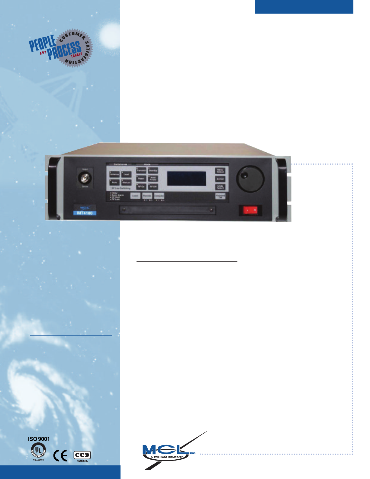
MT4100
BROADBAND CW TWT LAB AMPLIFIER
FOR RADAR, EMC AND EW TESTING
2.5 – 7.5 GHz 550W typ.
2.0 – 8.0 GHz 400W typ.
6.0 – 18.0 GHz 325W typ.
7.5 – 18.0 GHz 325W typ.
18.0 – 26.5 GHz 75W typ.
26.5 – 40.0 GHz 35W typ.
AVAILABLE
AMPLIFIER OPTIONS:
RF Input Attenuator
Other Options Are Available Upon Request
FEATURES:
Extensive Diagnostic
Capabilities
Advanced Thermal Design
Compact Size
Ducted Cooling
Quiet Operation
The MT4100 broadband amplifier is
leveraged around the field-proven
MT4000 TWT architecture. With its
modular design, compact and efficient packaging, the MT4100 will
exhibit unsurpassed reliability.
New users will find the MT4100, with
its intuitive front panel control, easy
to utilize. For those environments
where automation is required, the
MT4100 offers a complete set of serial command in RS485 or RS232 for
quick and easy hook-up to an
automation system. MCL also offers
a full line of controllers that will aid in
remote operation.
MCL, INC • 501 S. Woodcreek Drive, Bolingbrook, IL U.S.A., 60440-4999 • 630-759-9500 FAX: 630-759-5018
MITEQ • 100 Davids Drive, Hauppauge, NY U.S.A. 11788 • 631-436-7400 Fax: 631-436-7430
Page 2
MT4100
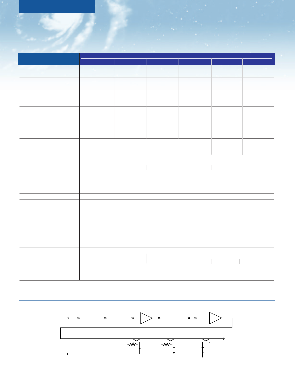
SSA
RF
INPUT
RF
OUTPUT
FWD. COUPLER
TEST POINT
TWT
REV. COUPLER
DETECTOR
FWD. COUPLER
DETECTOR
BROADBAND CW TWT LAB AMPLIFIER
ELECTRICAL
SPECIFICATIONS
535-2.5/7.5 450-2/8 300-6/18 250-7.5/18 50-18/26.5 40-26.5/40
MT4100
Mechanical Configuration Figure 1 Figure 1 Figure 2 Figure 2 Figure 2 Figure 2
Frequency Range (Fo) Standard 2.5 - 7.5 GHz 2.0 - 8.0 GHz 6.0 - 18.0 GHz 7.5 - 18.0 GHz 18.0 - 26.5 GHz 26.5 - 40.0 GHz
Output Power (min.):
HPA Rated Output (min.): 2.0 - 2.5 GHz
500 W 125 W (51.0 dBm) 250 W 250 W 45 W 35 W
(57.0 dBm) 2.5 - 8.0 GHz (53.7 dBm) (53.7 dBm) (46.5 dBm) (45.4 dBm)
370 W (53.2 dBm)
HPA Typical Output: 2.0 - 2.5 GHz
175 - 500 W
550 - 825 W (52.4-57.0 dBm) 325 - 350 W 320-350 W 75-95 W 35-65 W
(57.4 - 59.2 dBm) 2.5-8.0 GHz (55.1-55.4 dBm) (55.1-55.4 dBm) (48.7-49.8 dBm) (45.4-48.1 dBm)
475 - 725 W
(56.8-58.6 dBm)
Gain:
Large Signal (min.): 60 dB 45 dB 50 dB
Small Signal Gain (SSG) (min.) 63 dB 50 dB 60 dB
Attenuation Range with optional SSA: 20 dB
Maximum SSG Variation Over:
Full Band: 15 dB max. (7 dB max. with equalizer) 12 dB max. (5 dB max. with equalizer) 20 dB max.
Gain Stability: ±0.25 dB/24 hr. max (constant drive, line voltage and temp.)
Stability, Any Freq. 0 to +40°C: 6.0 dB typ.
Stability, Any Freq. ±10° Max.: 1.2 dB typ.
Input VSWR: 2.0:1 max. with respect to 50 ohms
Output VSWR: 2.5:1 typ.
Load VSWR: 2.0:1 max. without damage, continuous
Residual AM Noise, Max.:
To 10 kHz 40 dBc max.
10 - 500 kHz -20 (1.0 + Logƒ kHz) dBc
Above 500 kHz 57 dBc max.
Harmonic Output, Max.: -4 dBc
Noise & Spurious, Max.:
Transmit Band (Fo) -70 dBm/Hz
Prime Power:
Voltage: 180 - 264 VAC, single phase 100 - 264 VAC, single phase
Power Consumption: 2.7 KVA max. 1.9 KVA max. 900 VA max. 800 VA max.
Power Factor: 0.95 min.
In-Rush: 28A max.
Input Transients: EN61000-4-4, 4-5, 4-11 (Surge, Fast Transients, Line Dropout)
Note: Performance information is subject to change without notification. Contact MCL for the latest specifications (TN4100-1).
RF BLOCK DIAGRAM
Page 3

INCINC
A
MITEQ
COMPANY
CONTROL AND STATUS CAPABILITIES
TYPE
FUNCTION
Filament ON/OFF Units Select Fault Counter ON/OFF
Transmit/Standby *Hold Power ON/OFF Antenna Position (1:1)
Controls *RF ON/OFF Auto Switching (1:1) Load Position (1:1)
Reset Manual Switching (1:1) Local/Remote/Computer
*Attenuation
*Auto Power RF Reflected Power Alarm RF Reflected Power Fault
Tube Temperature Alarm RF High Alarm Filament Under Current Fault
Adjustable Parameters RF Low Alarm Comm Band Rate Comm Protocol
Comm Address Time
Date
RF Forward Power Helix Current RF Reflected Power
Displays Helix Voltage Tube Temperature Filament Current
Filament Delay PS Temperature
Tube Temperature Switch WG Pressure PS Temperature
Faults Tube Temperature Analog Helix Surge Current Chassis Interlock
(Notification, Helix Run Current HV Over Voltage Filament Under Current
RF & HV Shutdown)
HV Under Voltage
User Interlock
RF High RF Low PS Temperature
Alarms RF Reflected Tube Temperature RF Switch Failed
(Notification Only)
Blower Failed AC Low Line
Exciter
Delay Transmit Selected Sampler Port Cal Table
Summary Alarm Summary Fault RF Low Switching ON/OFF
Additional Status Computer Tx Computer Rx Remote Tx
Remote Rx Event Log Fault Log
Maintenance Log
* Optional
ENVIRONMENTAL
SPECIFICATIONS
Operating Temperature:
-1
0°C to +40°C
Non-Operating Temperature:
-4
0°C to +70°C
Relative Humidity:
95%, non-condensing
Operating Altitude:
10,000 ft. above sea level (3,048 m)
with standard adiabatic derating
Non-Operating Altitude:
50,000 ft. above sea level (15,240 m)
Vibration:
Method 514-4 of
MIL-STD-810E Procedure I, Figures 514.4-1,
514.4-2, 514.4-3
Shock:
10 g, 11ms
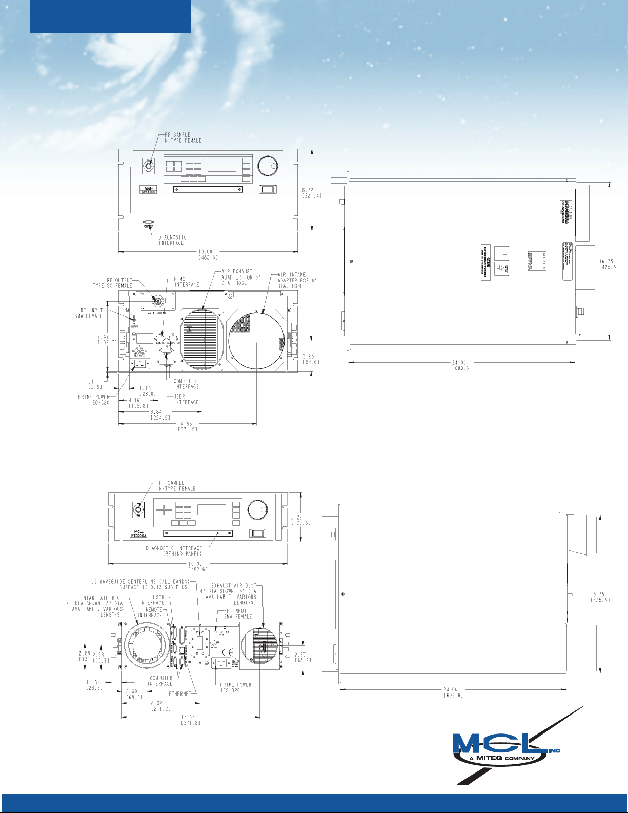
MECHANICAL
SPECIFICATIONS
RF Connectors:
Input: Type SMA female
Output: 2.0–8.0 GHz SC (Male)
6.0 – 18.0 WRD-650
7.5 – 18.0 WRD-750
Installed Weight:
Figure 2: 65 lbs.
Figure 1: 90 lbs.
Cooling:
Closed Loop Circuit
Page 4
INCINC
A
MITEQ
COMPANY
MT4100
OUTLINE DRAWINGS
Figure 1
535W – 2.5/7.5 GHz
450W – 2/8 GHz
Figure 2
300W – 6/18 GHz
250W – 7.5/18 GHz
50W – 18/26.5 GHz
40W – 26.5/40 GHz
Note: Mechanical dimensions are frequency band dependent.
MCL, INC • 501 S. Woodcreek Drive, Bolingbrook, IL U.S.A., 60440-4999 • 630-759-9500 FAX: 630-759-5018
24-HOUR CUSTOMER SUPPORT NUMBER IN THE USA: 1-800-743-4625
OUTSIDE THE USA: 312-461-4536
MITEQ • 100 Davids Drive, Hauppauge, NY U.S.A. 11788 • 631-439-9220 Fax: 631-436-7430
MT 4100-12.07
 Loading...