

Page 1
MBITE
Miniature Battery Impedance Test Equipment
■
Determines condition of lead-acid and
NiCd batteries on-line to 2500 Ah
■
Helps to ensure (Improves) critical
equipment back-up and (continuous)
revenue streams
■
Directly measures intercell connection
resistance and voltage
■
Standard and Custom Lead Sets available
■
17% smaller than the previous version
MBITE
Miniature Battery Impedance Test Equipment
DESCRIPTION
The Miniature Battery Impedance Test Equipment, MBITE,
is designed and ideally suited to determine the health of
flooded and sealed lead-acid and Ni-Cd batteries in
telecomm, RR signal and communications, substation,
process control and switchgear, emergency lighting
systems, smaller UPSs, and more. An additional
application is to measure impedance of batteries at the
end of the production line in battery manufacturing plants.
The MBITE is a lightweight, easy-to-use battery tester that
incorporates advanced features for enhanced capabilities
to provide fast, reliable results to determine what further
action may be required to ensure adequate system backup time. After all, measuring batteries is not for the
battery but for the equipment the battery is supporting
whether to ensure revenue streams or to support critical
plant equipment such as oil priming pumps.
In addition to measuring battery impedance and
interconnection resistance, the MBITE also measures
individual dc terminal voltages. Furthermore, since
impedance does not stress the battery, terminal voltages
may be used when they need to be documented. All
three parameters can be stored (up to 1000 lines of
readings) on-board for immediate review at the test site
on the large 31⁄2 digit LCD or from the built-in printer.
The stored data also can be downloaded via the RS-232
connector to a PC using “AVOLink” download software or
other conventional communications packages to
spreadsheet applications for further data interpretation.
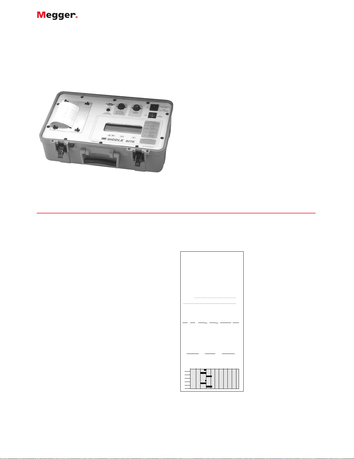
The Battery Analysis Report (see Figure 1) prints out cell
number, battery impedance, interconnection resistance,
cell dc voltage, date and time at which cell impedance is
recorded, total test current, and cell impedance summary
including graphical analysis. The printed header has space
to record user, location and cell IDs using the Bar Code
Wand listed in Optional
Accessories.
Unlike load cycle testing,
which involves substantial
downtime and performed
periodically, the MBITE
requires no battery discharge.
With a test time of less than
30 seconds per cell, it
measures internal cell
impedance, dc terminal
voltage and intercell
connection resistance without
taking batteries off-line. The
MBITE, like the original BITE,
is used to find weak cells due
to sulphation, post-seal
corrosion, and poor top lead
and intercell connections.
The test results, along with
user-supplied information
such as ambient temperature
and system ac ripple current,
will provide sufficient
information to evaluate the
overall battery system.
Figure 1.The Battery Analysis
Report (with Loc ID, User ID,
Notes, Cell ID filled-in)
Battery Analysis Report
Location ID:
USA Mobile Comm Site 37W Str 1A
User ID:
John Doe
Average Test Current: 0.98
Notes:
23-FEB-2000
TST Cell Zb mΩ RS mΩ Volts DC Time
001 1A01 2.46 0.356 6.18 10:56
002 1A02 2.34 0.359 6.23 10:57
003 1A03 2.65 0.341 6.23 10:57
004 1A04 2.47 0.355 6.18 10:58
005 1A05 2.34 0.337 6.23 10:58
006 1A06 2.65 0.347 6.23 10:58
Cell Impedance Summary
Minimum
001
002
003
004
005
006
Average Maximum
2.34 2.48 2.65
Percent Deviation from Average
-10 0 10 20 30
Page 2
Why Measure Batteries at all?
Measuring batteries is not for the battery but for the
equipment the battery is supporting whether to ensure
revenue streams as in wireless phone service or to support
critical plant equipment such as oil priming pumps. In a
sense, it is insurance that the MBITE provides and peaceof-mind knowing that the batteries are in good health.
APPLICATIONS
The MBITE measures impedance values and dc voltage for
flooded and sealed lead-acid and nickel-cadmium cells.
This information aids the operator to determine cell
replacement criteria based on impedance trends. The
MBITE also identifies weak cells in a battery string and
pinpoints unsatisfactory intercell and/or intertier
connections. A schematic diagram of a typical test setup is
shown in Figure 2.
Test Procedure
The MBITE base measurement unit applies a capacitively
coupled ac current to the battery under test by way of the
current source leads. Current sensors monitor source
current. The standard CT has a 2-in. (50-mm) internal
dimension while the optional CT is 0.5 in. (13 mm). The
CT is clamped around a convenient battery intercell or
intertier connection within the battery’s current loop. The
potential probes are placed across the cell under test. The
base measurement unit displays cell impedance and dc
float voltage as well as intercell connection resistance.
Figure 3 shows the value of taking direct intercell
connection resistance measurements. The information can
be verified by the operator and then stored by pressing the
data send button on the potential probe before moving
onto the next cell. Intercell resistance measurements also
can be made and
stored using the
cell/strap mode.
Single cell/module
applications
can be
accommodated
using one of the
optional Factory
Probe Lead Sets.
MBITE
Miniature Battery Impedance Test Equipment
Interpretation of Readings
Data produced by the MBITE can be interpreted in both
short- and long-term time frames. It is recommended that
MBITE measurements be made part of a battery
maintenance
program, with
readings taken
and recorded
quarterly or semiannually. Figure
4 shows an
example of how
impedance
changes as cells
weaken over time
and cycle life.
Short Term Interpretation
Impedance readings for individual cells can be used in the
short term to compare with the average impedance
reading for the entire battery. Individual cell values
varying by more than ±40% of the (sealed) battery average
typically indicate a problem with that cell (and ±20% for
flooded). There are two different methods of evaluating
impedance data in Excel
®
: 1) use the bar graph of the
MBITE printout in Cell # order and 2) by rearranging the
data into ascending impedance as shown in Figure 5 using
a spreadsheet. The cells on the right side of the graph are
weaker than the others. The dramatic increase in
impedance is a clear indication of questionable cells.
Further investigation of such cells is recommended,
including a
verification of
intercell
connections,
specific gravity,
if appropriate,
ambient
temperature, and
perhaps, a single
cell load-cycle
test.
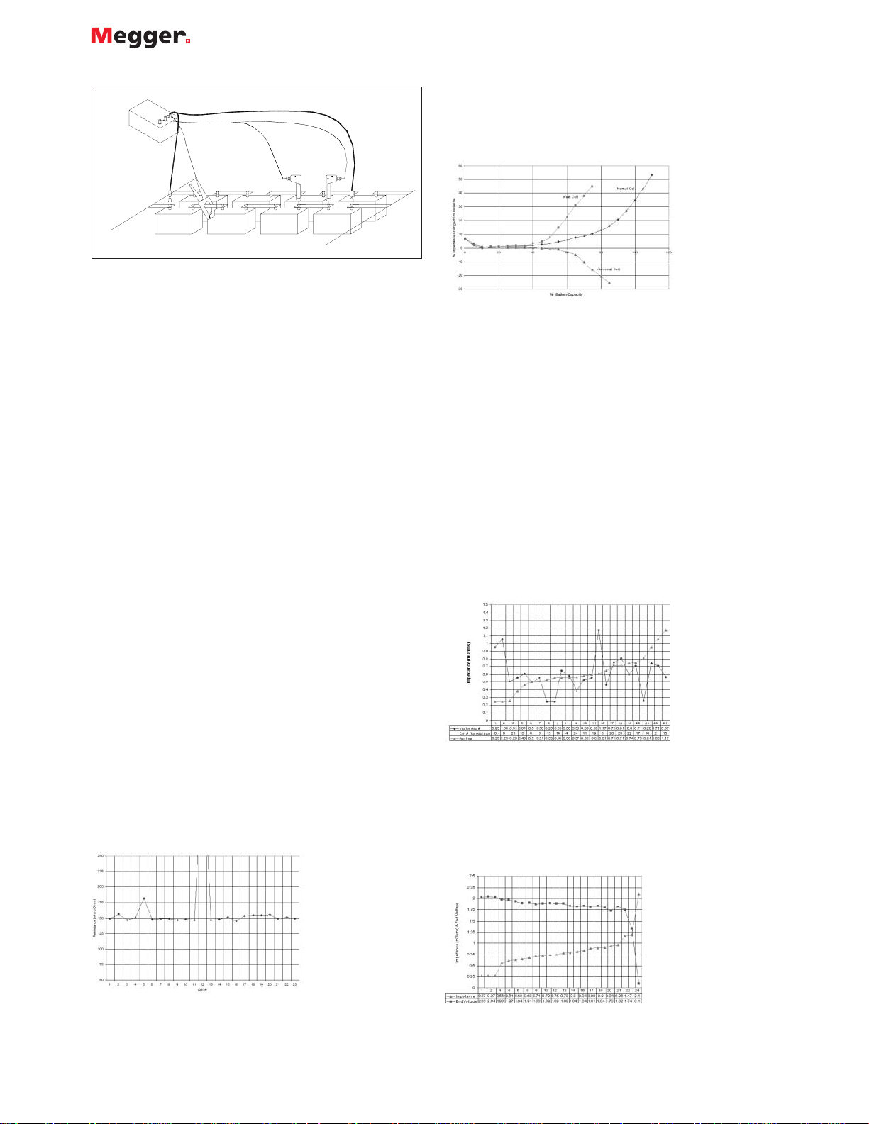
Long-Term Interpretation
Impedance readings can be used in the long term to
determine replacement criteria. Battery cell impedance
values should be recorded and compared to previous
readings to determine
the cell’s position on
the curve of
impedance versus cell
life. Individual cell
values varying by
more than ±40% from
the initial baseline of
the battery average
typically indicate a
problem with that cell
(and ±20% for
Figure 2. A typical test set-up.
(-)
(+)
Figure 3. Intercell Connection
Resistance.
Figure 4. Impedance increases with
battery age (and weakness.)
Figure 5. Ascending Impedance.
Figure 6. Ascending Impedance
compared to Load Test,
Page 3

MBITE
Miniature Battery Impedance Test Equipment
flooded). A sample curve is shown in Figure 4. In order
to facilitate the long-term interpretation of impedance
values, Megger maintains a database of impedance values
of many battery types. For comparison purposes, this
information is available upon request.
An additional data evaluation method that can be used in
either a short-term or a long-term mode is in conjunction
with load test data. By taking impedance measurements
just prior to a load test and comparing them with end
voltage, a correlation between impedance and that string’s
capacity can be derived. See Figure 6.
FEATURES AND BENEFITS
■
Provides excellent data to evaluate critical systems’
back-up time
■
On-line testing requires no downtime
■
Graphical printout aids to quickly determine cell/jar
condition to make immediate decisions
■
Data is stored for on-site review
■
Requires no battery discharge to save cycle life
■
Built-in printer to leave a record at the site
■
RS-232 connector for downloading stored data to PC
■
Reduced testing time; less than 30 seconds per cell
■
Measures impedance and dc cell voltage for lead-acid
and nickel-cadmium cells
■
Directly measures intercell connection resistance to
eliminate routine retorquing
■
Up to 1000 sets of readings can be stored in an
unlimited number of tests
■
Custom Lead Sets available to meet specific needs
SPECIFICATIONS
Maximum Total Voltage at MBITE Leads
250 V dc. Larger battery systems can be sectioned
Power Requirements
120 V ac 60 Hz (240 V ac 50 Hz on –47 and –47-CE models)
Display
Backlit LCD panel with 5-in. (125 mm) viewing area
Voltage Range
0 to 2.500 V dc, 1 mV resolution
2.5 to 25.00 V dc, 10 mV resolution
Impedance Range
0 to 1.000 mΩ 1 µΩ resolution
1 to 10.00 mΩ 10 µΩ resolution
Measurement Accuracy
AC impedance: ±(5% rdng + 1 lsd)
DC voltage: ±(1% rdng + 1 lsd)
Settling Time per Reading
3 seconds maximum
Temperature
Operating: 32° F to 104° F (0° C to 40° C)
Storage: -5° F to 130° F (-20° C to 55° C)
Humidity: 20% to 90% RH, non-condensing
Clamp Range
Standard Opening: 2.0 in. (50 mm) maximum
Optional Opening: 0.5 in. (12 mm) maximum
Safety
Designed to meet IEC 1010-1 specifications
Dimensions: 7H x 11D x 17W in. (18 H x 29 D x 45 W cm)
Weight: 19.5 lbs. (8.8 kg)
Item (Qty) Cat. No.
MBITE, 110/60 246005B
MBITE, 240/50 246005B-47
MBITE, 240/50, CE-marked 246005B-47-CE
Included Accessories
Potential Probe set 33530
Potential Probe cable (8 ft.) 33806
Fused Current Source Leads (8 ft.) 33805
Clamp-on current sensor, CT, with 1⁄2 in. opening (5 ft.) 33863
Extension cable, CT (6 ft.) 33864-1
AVOLink, downloading software Instruction manual AVTM246005B
Optional Accessories
Potential Probe extension cable (8 ft.) 33806
Extension cable, CT (20 ft.) 246033
Clamp-on current sensor, CT, with 1⁄2 in. opening 246034
Factory Probes, dual-point helical hand spikes 33532
Factory Probes, AMP/Burndy Lead Set 33531
Bar Code wand with preprinted, laminated code sheet 246036
Bar Code Label printing software 246039
ORDERING INFORMATION
Page 4

UK
Archcliffe Road, Dover
CT17 9EN England
T (0) 1 304 502101
F (0) 1 304 207342
UNITED STATES
4271 Bronze Way
Dallas, TX 75237-1018 USA
T 1 800 723 2861
T 1 214 333 3201
F 1 214 331 7399
OTHER TECHNICAL SALES OFFICES
Norristown USA, Toronto CANADA,
Mumbai INDIA,
Le Raincy FRANCE, Cherrybrook
AUSTRALIA, Guadalajara SPAIN
and The Kingdom of BAHRAIN.
ISO STATEMENT
Registered to ISO 9001:1994 Reg no. Q 09250
Registered to ISO 14001 Reg no. EMS 61597
MBITE_DS_en_V01
www.megger.com
Megger is a registered trademark
MBITE
Miniature Battery Impedance Test Equipment
 Loading...