

Page 1
Technical Data Sheet
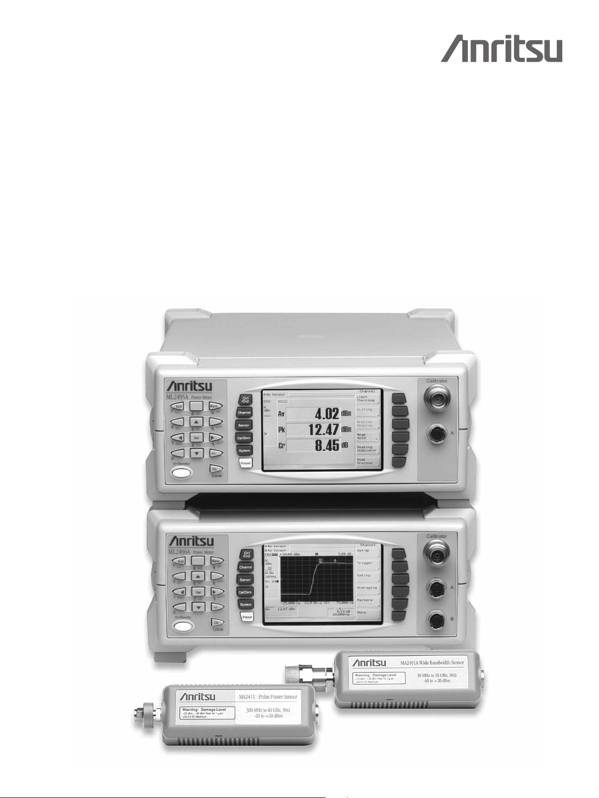
The Anritsu Family of Pulse, Wideband and
CW Power Meters, and Power Sensors
ML2400A Power Meters and MA2400A/D Power Sensors
Ideal solutions for Average, Peak, and Crest Power measurements
Anritsu Power Meters and Power Sensors:
Accurate, Fast, and
Affor
dable.
Page 2

Introduction
Anritsu offers the world's most comprehensive range of power meters. The ML2490A series has the performance required
or narrow fast rising-edge pulse power measurements (e.g., radar), while the ML2480A series is suited for Wideband power
f
easurements on signals such as W-CDMA, WLAN, and WiMAX. The ML2430A series of power meters are designed for
m
CW applications, offering a combination of accuracy, speed and flexibility in a low cost package.
lso available are five different families of power sensors with frequency coverage to 50 GHz and dynamic range up to 90 dB.
A
Most of the power sensors can work in either pulsed/modulated or CW mode (the ML2480/90A series meters offer both modes).
n choosing a power sensor, several factors must be considered, including: frequency range, dynamic range and the modulation.
I
The rise time of the sensor should also be chosen to match the rise time of the modulation.
2
Page 3

Power Meter Specifications
L2430A Series ML2480A Series ML2490A Series Comments
M
L2437A ML2438A ML2487A ML2488A ML2495A ML2496A
M
Signal Inputs 1 2 1 2 1 2
requency range 100 kHz to 65 GHz (sensor dependent)
F
ynamic range –70 to +20 dBm (dependent on sensor, external coupler or attenuator) Continuous or Peak
D
ulse/Modulated mode
P
65 MHz range 7
>
>38 MHz range 8
16 MHz range 9
>
Repetitive Sampling)
(
0 MHz (One shot)
2
ombined B/W (with MA2411B sensor)
C
>39 MHz range 7
29 MHz range 8
>
>12 MHz range 9
MA2411B nominal Bandwidth = 50 MHz
W mode
C
7 kHz range 1,2,3,4
1
36 Hz range 5
Auto/Manual
CW Mode
5 kS/s
7
ulse/Modulated Mode
P
31.25 kS/s to 62.5 MS/s Continuous Sampling
Trigger capture time 3.2 µs to 7s,
(
200 data points)
1 GS/s Random Repetitive Sampling
(Trigger capture time 50 ns - 3.2 ns,
200 data points)
Conflicts between selected settings and other
instrument settings are indicated through user
warnings (displayed and GPIB)
Nominal Video BW
Sampling rate
erformance
P
100 kHz (Profile mode)
31.25 kS/s
ulse/Modulated mode
P
20 MHz with MA2491A sensor
CW mode
7 kHz ranges 1–4
1
35 Hz range 5
Auto/Manual
W Mode
C
5 kS/s
7
ulse/Modulated Mode
P
1.25 kS/s to 64 MS/s
3
(dependent on trigger capture time)
Accuracy
(Defined by
uncertainty
calculations with
relevant sensor
and source match
conditions)
N/A
N/A 10% to 90% Rise-time measurement of –20 dBm to +20 dBm Peak power (with MA2491A)
N/A ≤3% in linear power at +10 dBm
N/A ±100 ppm (1 GHz clock for RRRS mode)
<0.5%
<0.5% of full scale in most sensitive range,
measured over one hour with maximum
averaging after one hour warm up at constant
temperature
<18 ns
(with MA2411B sensor)
CW Mode
<0.5% (±0.02 dB absolute Accuracy, ±0.04 dB relative Accuracy)
Pulse/Modulated Mode
<0.8% Nominal range 7, 8
Equivalent Noise Power
(256 Moving
Range 1
Range 2 50 nW 100 nW
Range 3 0.5 nW 2 nW
Range 4
Range 5 50 pW 0.5 nW
(CW mode)
Range 7 20 µW 68 µW
Range 8 3 µW 10 µW
Range 9
(Pulse/Modulated mode)
verage)
A
MA2472D MA2491A
0.5 µW
0.2 nW
2 µW
2 µW
1 nW
8 µW
Typical 8 ns, Maximum 12 ns
(with MA2411B sensor)
Fall-time typically 11 ns
Equivalent Noise Power
(256 Moving
Range 1
Range 2 50 nW 100 nW
Range 3 0.5 nW 2 nW
Range 4
Range 5 50 pW 0.5 nW
(CW mode)
Range 7 5 µW 15 µW
Range 8 1 µW 5 µW
Range 9
(Pulse/Modulated mode)
verage)
A
MA2472D MA2491A
0.5 µW
0.2 nW
0.5 µW
2 µW
1 nW
2 µW
System rise-time
(10% to 90% at +10 dBm)
Rise-time measurement
dynamic range
Overshoot
(Pulse/Modulated mode)
Sampling Rate
Clock Accuracy
Instrumentation Accuracy
Zero set and Drift
3
Page 4
Power Meter Specifications continued
L2430A Series ML2480A Series ML2490A Series Comments
M
L2437A ML2438A ML2487A ML2488A ML2495A ML2496A
M
2
Power vs. Time graphic of readout data
r Profile of Peak power for analysis of
o
epetitive pulse or transient waveforms
r
ingle channel power sweep or frequency sweep Source sweep
S
peration
O
±5 dB range CW (Readout mode) only Peaking meter
Dynamic range covered by five overlapping
mplifier ranges, R1, R2, R3, R4 and R5
a
niversal Sensor MA2481/82D ranges 1 to 6
U
2 (CW or Pulse/Modulated measurement modes)
(Pulse/Modulated measurement mode)
2
Pulse modulated mode:
Dynamic range covered by three overlapping amplifier ranges, R7, R8 and R9
W mode:
C
ynamic range covered by five overlapping amplifier ranges, R1, R2, R3, R4 and R5
D
Universal Sensor MA2481/82D ranges 1 to 6
easurement Display-
M
eadout (Numerical)
R
Measurement Display-
rofile (Graph)
P
mplifier Range
A
Features
(summary)
Auto or Manual
(current range or selectable 1 through 5)
0.1 to 0.001 dB
Linear power units, 3 to 6 digit, 1 to 3 digits
electable to right of decimal nW to W;
s
oltage, 1 to 2 digits selectable to right
V
of decimal
0.01 dB
Profile and P vs. T modes:
200 pixels display resolution
For a 1 ms Profile window, cursor resolution
on the display is 5 µs
Hold, Max, Min Measurement hold
Average, Min, Max Average, Min, Max, Peak, Crest, PAE (Power Added Efficiency) Measurements
— PDF, CDF, CCDF Power statistics
0.00 to 20.00V nominal
Watt, %, Volts
dBm, dB, dBµV, dBmV, dBr dBm, dBW, dB, dBµV, dBmV
–199.99 to +199.99 dB Display range
1
2
Automatic or manual. When in manual clear indication given to user
(display and GPIB) of fault conditions (under or over-range)
.1 to 0.001 dB
0
ns (RSS mode)
16 ns
Pulse/Modulated mode
15 µs
CW Mode
Four Independently set Gates or eight repeated Gates
One Fence per Measurement gate
Gate measurement supports Average, Peak, Crest, Max and Min
Four Markers and One Delta Marker, Marker to Max/Min, Pulse Rise/Fall-time,
Pulse Width, Off Period, Pulse Repetition Interval
Rise Fall/Search Parameter Variable %
Reference: Max Marker or Gate Power Level
1
16 ns (non RSS mode)
Pulse/Modulated mode
15 µs
CW Mode
Range Hold
Display resolution in
eadout mode
R
Display resolution in
rofile mode
P
Time measurement
resolution
Voltage
measurement range
Display units (Lin)
Display units (Log)
Measurement Gates
Markers
Fixed value high and low limits with audible,
rear panel TTL output, and/or visible
Pass/Fail alarm indication
Failure indication can latch for
transient failure detection
–199.99 to +199.99 dB (Fixed value or frequency dependent table) Of
Simple pass/fail for CW
Complex limits for pulsed and TDMA systems
30 Limits Stores available on the instrument
4
Limit lines
fset range
Page 5

Power Meter Specifications continued
L2430A Series ML2480A Series ML2490A Series Comments
M
L2437A ML2438A ML2487A ML2488A ML2495A ML2496A
M
Auto (Moving), Manual (Moving, Repeat) Type
to 512 Range
1
veraging
A
ow, Medium and High settings apply
L
ost average low pass filter to improve
p
visibility at high display resolution
nternal, External (TTL or RF Blanking),
I
GPIB, Manual, Continuous
anual
M
Single power value set to cover entire measurement dynamic range of sensor
Auto
utomatically sets trigger level for signal over measurement dynamic range
A
/A Low-level Averaging
N
nternal, External (TTL), GPIB,
I
Continuous, External Bus
Continuous (not in Random
epetitive Sampling mode) Internal,
R
External TTL (Rising or falling Edge),
PIB or external Bus
G
ource
S
Trigger modes
Triggering
N/A
Sets the trigger arming, unless the trigger
ource is set to EXTTTL
s
hen ARMING is set to Blanking ON, only
W
samples taken when the rear panel Digital
nput BNC is active will be averaged in the
I
measurement
/A 0 to 64 x trigger capture time range or 120s whichever is the greater
N
–15 to 20 dBm (all diode sensors,
selectable to –25 dBm)
1 dB
0.1 dB
N/A
0.0 to 999 ms
TTL rising or falling edge (BNC input) External Trigger range
N/A 90% of trigger capture range Pre-trigger range
ontinuous Sampling Modes:
C
ingle
S
Automatic
rame for QAM and multi-pulse
F
–15 to 20 dBm
±16 ns or display resolution
whichever is the larger
(Trigger Capture time 3.2 µs to 7s)
0.0 to 999 ms
Dependent on trigger capture time
Variable-auto set and manual
20 MHz, 2 MHz, 200 kHz, 20 kHz
Repetitive Sampling Modes:
utomatic
A
rame for QAM and multi-pulse
F
Continuous Sampling Modes:
Single
utomatic
A
Frame for QAM and multi-pulse
–28 dBm to +10 dBm with MA2472D
CW mode
–18 dBm to +14 dBm with MA2491A
–30 dBm to +10 dBm with MA2472D
Pulse/Modulated mode
±2 ns or display resolution,
whichever is the larger
(Trigger Capture time 50 ns to 3.2 µs)
±16 ns or display resolution
whichever is the larger
(Trigger Capture time 3.2 µs to 7s)
Pulse modulated mode
Pretrigger (-ve): 95% of the
Trigger Capture range
Post Trigger: Set by 256K buffer
and sample rate
CW mode
rigger Only: 0-999 ms depending
T
Post
on Trigger Capture period setting
Nominal Internal Trigger
Bandwidth
Arming Sources
rame Arming
F
Time range
Internal Trigger dynamic
range
Internal Trigger level
Accuracy (typical)
Internal Trigger
settable resolution
Trigger time resolution
Uncertainty
rigger delay range
T
0.5% of display period or 100 ns 0.5% of display period or 16 ns
5
200 display points
1 ns or 0.5% of trigger capture time,
whichever is the larger
400 display points
1 ns or 0.25% of trigger capture time
(400 points), whichever is the larger
Trigger delay settable
resolution
Page 6

Power Meter Specifications continued
L2430A Series ML2480A Series ML2490A Series Comments
M
L2437A ML2438A ML2487A ML2488A ML2495A ML2496A
M
/A ±2 ns for pre and post trigger (Trigger capture time of 3.2 µs or 50 ns) Trigger delay uncertainty
N
/A ±15 ns (20 MHz trigger BW) Trigger latency
N
Profile mode: 10 ms to 7s
v T mode: 1m to 24 hrs
P
3.2 µs to 7s 50 ns to 7s
Trigger/Display
apture range
c
riggering
T
System Configuration
00 display points
2
16 ns or 0.5% of trigger capture time,
hichever is the larger
/A
N
On-screen indicator/message
0 storage registers
1
plus RESET default settings
Wipes non-volatile memory on power up when active. Secure mode
Yes No Remote monitoring
es No Modem Compatibility
Y
>600 readings/sec (per input channel)
Emulation of Anritsu ML4803,
Agilent 436, 437 and 438
Supports software download, Instrument
control and modem dial-out.
1200, 2400, 4800, 9600, 19200, 38400,
57600 Baud rates supported
w
00 display Points
4
16 ns or 0.25% of trigger capture time,
hichever is the larger
w
rigger point depicted by trigger edge waveform. Edge represents trigger point of signal.
T
Display position of trigger edge waveform adjustable
20 settings stores
reset accessible on Front Panel
P
Offset tables
>400 readings/sec in CW mode.
10 Sweeps/sec in Profile mode
(200 data points/sweep, Binary float
output format, 5 µs Trigger capture time)
>350 readings/sec
(Fast Mode, Gate output, 1 µs gate width)
Supports software download and Instrument control
1200, 2400, 4800, 9600, 19200, 38400, 57600 Baud rates supported
00 display points
2
1 ns or 0.5% of trigger capture time,
hichever is the larger
w
00 display Points
4
1 ns or 0.25% of trigger capture time,
hichever is the larger
w
>400 Readings/second CW Mode [TR3 mode]
350 Readings/second Pulse/Modulated
>
Mode (Continuous Sampling) [1 µs pulse,
readout mode, Display turned off, TR3 Mode]
>10 profile transfers/sec Pulse/Modulated Mode
(Profile data) [200 points per sweep, Binary
Float Output, 5 µs Trigger Capture Time]
>20 Readings/sec Pulse/Modulated Mode
(Repetitive Sampling) [50 ns pulse, readout
mode, Display turned off, TR3 Mode]
Back Compatible with ML2480A with
Additional functionality added
Trigger capture time
ettable resolution
s
rigger point display
T
(on-screen)
ave/Recall
S
GPIB
(IEEE–488.2, IEC–625)
RS232
Interfaces
Operating Modes:
Display voltage reading on selected channel
oltage proportional to frequency for
V
sensor calibration factor compensation
Blanking Input -TTL levels only
Selectable positive or negative polarity
Input Range: 0 to 20V
Resolution: 0.5 mV
Control: Adjustable voltage to
frequency relationship
TTL, maximum frequency of 800 kHz TTL, maximum frequency of 1 MHz TTL, maximum frequency of 10 MHz External trigger (BNC)
Two outputs configurable to Log or Lin
Operating Modes:
Selectable channel adjusted for
calibration factors and other power
reading correction settings
Pass/Fail -Selectable TTL High or Low
Channel output -Near real time analog
Uncalibrated
AC Modulation Output -Output 1 only
Dwell Output -Output 2 only
Output Range: –5.0 to 5.0V
Resolution: 0.1 mV
Can be configured for:
Cal factor correction from synthesiser
Ext Voltage Voltmeter,
Connection:- current probe for PAE applications
Output 1 can be configured for:
Analog Output,
Pass/Fail
Levelling: -Sensor Input
Output 2 can be configured for:
Analog Output,
Pass/Fail TTL o/p Limits,
Levelling: -Sensor Input B,
rigger Output
T
TTL
o/p Limits,
A
,
Cal Factor V
(BNC)
Analogue Output (BNC)
oltage Input
6
Page 7

Power Meter Specifications continued
L2430A Series ML2480A Series ML2490A Series Comments
M
L2437A ML2438A ML2487A ML2488A ML2495A ML2496A
M
mW Power
1
ower accuracy
1.2% per year, ±0.9% RSS
±
eference Calibrator
R
isplay
D
xternal Video Output N/A CRT 1/4 VGA External Video Output
E
arallel Printer Port
P
eneral MIL-T28800F, class 3
G
Non Volatile
AM Battery
R
attery Option >6 hr usable with 3000 mAhr (NiMH) battery N/A
B
DC Power Requirements
AC Power Requirements
50 MHz (nominal) 50 MHz, 1 GHz (optional) Frequency
1% (50 MHz)
<1%
<1.04
N female Connector type
onochrome LCD, with backlight and
M
adjustable contrast
Compatible with Deskjet 540 and
40 Models. Other 500 Series and
3
300 Series and later are typically
compatible. Also Canon BJC 80
ithium (10 year life) Lithium (5 year life)
L
2 to 24 VDC, Reverse protected to –40V
1
aximum input 30V
M
90 to 250 VAC, 47 to 440 Hz,
40 VA Maximum
<
<2% (1 GHz)
<1.12 (50 MHz)
1.2 (1 GHz)
<
olor LCD Display
C
/A
N
N/A
90 to 250 VAC, 47 to 440 Hz
P
Traceable to National
(
tandards)
S
Frequency Accuracy
VSWR
EMI, EMC, Safety Complies with requirements for CE marking EN 61326, EN61010-1
Operating Temperature 0° C to 50° C
Storage Temperature –40° C to 70° C
Moisture Splash and rain resistant, 95% humidity non-condensing
Dimensions 213 mm x 88 mm x 390 mm Width x Height x Depth
Weight 3 kg (excuding battery option) 2.8 kg 3 kg
Warranty 1 year Standard, 3 year Optional
Mainframe only,
see sensor specification
for performance
of sensors
7
Page 8

Power Sensor Specifications
requency Range
F
CW Dynamic Range
dBm)
(
WR
S
Standard Diode Sensors
1.17; 10 to 150 MHz (MA2472D only)
MA2472D 10 MHz to18 GHz
70 to +20 CW Mode
MA2473D 10 MHz to 32 GHz K (m)
A2474D 10 MHz to 40 GHz K (m)
M
A2475D 10 MHz to 50 GHz V (m)
M
–
30 to +20 (with ML2480A)
–
34 to +20 (with ML2490A)
–
Pulse/Modulated Mode
<
1.90; 10 to 50 MHz
<
<1.17; 50 to 150 MHz
1.12; 0.15 to 2 GHz
<
1.22; 2 to 12.4 GHz
<
<1.25; 12.4 to 18 GHz
1.35; 18 to 32 GHz
<
<1.50; 32 to 40 GHz
<1.63; 40 to 50 GHz
0.004
<
Temperature accuracy: <1% < 40 GHz, <1.5% <50 GHz, 5 to 50º C
High Accuracy Diode Sensors
<1.90; 10 MHz to 50 MHz
1.17; 10 MHz to 150 MHz (MA2442D only)
MA2442D
A2444D
M
10 MHz to 18 GHz
0 MHz to 40 GHz
1
67 to +20
–
<
1.17; 50 MHz to 150 MHz
<
<1.08; 150 MHz to 2 GHz
1.16; 2 GHz to 12.4 GHz
<
0.004
<
<1.21; 12.4 GHz to 18 GHz
A2445D 10 MHz to 50 GHz V (m)
M
<1.29; 18 GHz to 32 GHz
1.44; 32 GHz to 40 GHz
<
<1.50; 40 GHz to 50 GHz
emperature accuracy: <1% < 40 GHz, 5 to 50ºC
T
Universal Power Sensors
MA2481D
MA2482D
10 MHz to 6 GHz
10 MHz to 18 GHz
–60 to +20
Temperature accuracy: <1%, 5 to 50º C
MA2480/01 Adds fast CW mode to Universal Power Sensors for high speed measurements of CW signal plus TDMA and pulse measurements
<1.17; 10 to 150 MHz
<1.12; 0.15 to 2 GHz
<1.22; 2 to 12.4 GHz
<1.25; 12.4 to 18 GHz
<0.004
(with option 1 only)
Wideband Sensors
MA2490A
MA2491A
3
3
50 MHz to 8 GHz
50 MHz to 18 GHz
Temperature accuracy: <1% 10 to 45º C
–60 to +20 CW Mode
–25 to +20 (with ML2480A)
–30 to +20 (with ML2490A)
Pulse/Modulated Mode
<1.17; 50 to 150 MHz
<1.12; 0.15 to 2.5 GHz
<1.22; 2.5 to 8 GHz
<1.17; 50 to 150 MHz
<1.12; 0.15 to 2.5 GHz
<1.22; 2.5 to 12.4 GHz
<1.25; 12.4 to 18 GHz
<18 ns
Pulse Sensor
1B
MA241
Requires 1 GHz calibrator
300 MHz to 40 GHz –20 to +20 dBm
option 15 to be fitted
emperature accuracy: <2% 10 to 45º C
T
1
0.0 dBm, room temperature with standard 1.5m sensor cable.
2
Each MA2400A/D Series sensor incorporates precision RF connectors with hexagon
coupling nut for attachment by industry standard torque wrench.
3
MA2490/1A
ML24950A Power Meters.
4
For Linearity on MA2475D only applicable to –70 to +15 dBm.
and MA2411B sensors must be used with ML2480A or
<1.15; 0.3 to 2.5 GHz
<1.35; 2.5 to 26 GHz
<1.50; 26 to 40 GHz
<8 ns
<18 ns when used
with ML2487/8A
5
For Linearity on MA2445D only applicable to -67 to +15 dBm.
6
Sensor linearity specifications are ± value.
Pulse/modulated performance only specified with 1.5m sensor cable length option
ML2400A-20 supplied as standard with the power meter.
ise Time
R
(ms)
1
S
.8%, <18 GHz
1
2.5%, 40 GHz
.5%, <50 GHz
3
For MA2475D
1.8%, <18 GHz
2.5%, <40 GHz
.5%, <50 GHz
3
For MA2445D
10 MHz to 6 GHz
3% –60 to +20 dBm
6 to 18 GHz
3% –60 to 0 dBm
3.5% 0 to +20 dBm
(1.8% CW with option 1)
<7% 50 to 300 MHz
<3.5% 0.3 to 8 GHz
<7% 50 to 300 MHz
<3.5% 0.3 to 18 GHz
<4.5% 0.3 to 18 GHz
<7% 18 to 40 GHz
ensor Linearity
4
5
6
onnector
C
N (m)
N (m)
(m)
K
N (m)
N (m)
N (m)
K (m)
RF
2
8
Page 9

Measurement Accuracy
P
ower Sensor
Reflection Coefficient = Γ
2
Reflection Coefficient = Γ
1
P
0
% Mismatch Uncertainty = 100 [(1 ± Γ1Γ2)2–1]
dB Mismatch Uncertainty = 20 log (1 ± Γ
1Γ2
)
NIST, National Institute of Standards and Technology
Anritsu, Microwave Measurement Division Standards Labs
Anritsu Service Factory Customer Cal Lab
Power Meter End User
Power measurement accuracy can be split into several parts.
he table below shows how the measurement uncertainty is
T
omposed for several power sensors. The source is presumed
c
to be a 16 GHz, 12.0 dBm signal with a source SWR of
1.5:1.
The uncertainties can be calculated as an RSS term as each
arameter is independent. Alternatively they can be added
p
together for a worst-case analysis.
A2440DMA2491AMA2470D
M
nstrumentation Accuracy
I
Sensor Linearity 1.80% 3.50% 1.80%
oise, 256 Avg.
N
ero Set and Drift
Z
Mismatch Uncertainty 3.84% 4.49% 4.49%
ensor Cal Factor Uncertainty
S
eference Power Uncertainty
R
Reference to Sensor Mismatch Uncertainty 0.23% 0.31% 0.23%
emperature Linearity
T
RSS, Room Temp 4.51% 6.06% 5.09%
Sum of Uncertainties, Room Temp 8.36% 11.59% 9.06%
SS
R
Sum of Uncertainties 9.36% 12.59% 10.06%
The Instrumentation accuracy of 0.5% is a very small
component of the overall uncertainty budget and describes
the linear voltage measurement accuracy of the power
meter.
0
0
0
0
1
1
4
.50%
.00%
.00%
.79%
.20%
.00%
.62%
0
0
0
1
1
1
6
.50%
.00%
.00%
.59%
.20%
.00%
.14%
0
0
0
0
1
1
5
.50%
.00%
.00%
.84%
.20%
.00%
.18%
Mismatch is easily calculated in either dB or percentage terms from the source’s and
ensor’s respective reflection coefficients.
s
The source match of the device under test can be improved
by the use of precision attenuators with good return loss or
by the use of external levelling with a high directivity
coupler or splitter.
Connector damage has significant accuracy and repeatability effects, and is also the most common cause of sensor
damage – although it is frequently undetected. Every
MA2400A/D Series includes a hex nut connection for
application of a calibrated torque wrench. Torque wrenches
assure compliance with the quality requirement and result in
more consistent measurements.
Sensor calibration factor uncertainty identifies the accuracy
of the sensor's calibration relative to a recognized standard for
absolute power level. Sensor calibration factor uncertainty is
included in accuracy calculations for any absolute power
measurement (in dBm or Watts) and for relative power
measurements if the signals are different frequencies.
Sensor linearity describes the relative response over the
dynamic range of the sensor, and is included when the sensor is measuring power levels relative to the 0 dBm calibrator reference level. Temperature linearity is included when
operating the sensor at other than room temperature.
Noise, Zero Set and Drift are all measured on the lowest
power range of the power sensor. Different types of power
sensors have different noise characteristics. Noise can be
reduced by averaging.
Mismatch uncertainty is typically the largest component of
the uncertainty budget – caused by the different impedances
of the device under test and the sensor. To help resolve this
issue, the sensor has been designed to have a good return
loss over a wide frequency range, typically achieving
significantly better results than the specification. In many
cases the major contributing factor is the match of the
source under test.
ML2400A Series is NIST traceable for more accurate, dependable measurements.
Reference power uncertainty specifies the maximum
possible output drift of the power meter's 50 MHz,
power reference between calibration intervals.
dBm
0.0
Reference power uncertainty and reference to sensor
mismatch uncertainty do not generally impact relative
power measurements.
See the Anritsu website (www.anritsu.com) for more
information and tool to calculate measurement uncertainties.
9
Page 10

Ordering Information
ower Sensor and Power Meter Selection Guide
P
ensors
S
Power measurement Average (RMS) RMS Average (RMS), Peak Average (RMS), Peak Average (RMS)
Measurement Application
examples)
(
Compatible Power meter(s) ML24xxA ML24xxA ML2490A, ML2480A ML2490A, ML2480A ML24xxA
Choose the right sensor and meter for your measurement application.
Standard Diode Universal Wideband Pulse (High Accuracy) Diode
A2470D Series
M
CW, GMSK, GFSK, 8PSK
TDMA, FDMA, IS136
A2480D Series
M
W, GMSK, GFSK,
C
8PSK, QPSK, QAM
TDMA, FDMA, CDMA,
FDM
O
A249xA Series
M
W, GMSK, 8PSK,
C
QPSK, QAM
TDMA, FDMA, CDMA,
FDM, Radar
O
A2411B
M
Pulse, QAM CW, GMSK Modulation
Radar, OFDM TDMA, FDMA Access Scheme
A2440D Series
M
omments
C
Power Meter Models
ML2495A Power Meter, Single Input
ML2496A Power Meter, Dual Input
ML2487A Power Meter, Single Input
ML2488A Power Meter, Dual Input
ML2437A Power Meter, Single Input
ML2438A
Power Meter, Dual Input
ML2490A Series
ML2490A–06 Rear Mount Input A
ML2490A–07 Rear Input A and Reference
ML2490A–08 Rear Mount Inputs A, B and Reference
ML2490A–09 Rear Mount Inputs A and B
ML2490A–33 Extra Operating Manual
ML2490A–34 Extra Programming Manual
ML2490A–37 Electronic Manuals
ML2490A–98 Calibration to Z540, ISO Guide 25
ML2490A–99 Premium Calibration
ML2480A
ML2480A–06 Rear Mount Input A
ML2480A–07 Rear Input A and Reference
ML2480A–08 Rear Mount Inputs A, B and Reference
ML2480A–09 Rear Mount Inputs A and B
ML2480A–15 Factory Fitted 50MHz and 1GHz Calibrator
ML2480A–15R Retro Fit Calibrator Kit
ML2480A–33 Extra Operating Manual ML2487/8A
ML2480A–34
ML2480A–35 Extra Operating Manual: Japanese
ML2480A–36 Extra Programming Manual: Japanese
ML2480A–37 Electronic Manuals only
ML2480A–98 Calibration to Z540, ISO Guide 25
ML2480A–99 Premium Calibration
ML2400A–32A Maintenance Manual ML2480/90A Series
ML2400A–31A Option 31, Extra Operation/Prog manual ML2480A
Options 1, 3 and 5 are mutually exclusive for any given ML2480/90A.
Options 6, 7, 8 and 9 are mutually exclusive for any given ML2480/90A.
ML2430A
10585–00003 Maintenance Manual ML2400A Series
ML2400A–33 Extra Operating & Programming Manual ML2437/8A
MA2499B Anritsu 4700 & 4600 Series Sensor Adapter
ML2400A–06 Rear Mount Input A on ML2437A
ML2400A–07 Rear Input A and Reference on ML2437A
ML2400A–08
ML2400A–09
ML2400A–11 NiMH Battery with Desktop Charger
ML2400A–11A NiMH Battery with Desktop Charger
ML2400A–22 3m Sensor Cable
ML2400A–23 5m Sensor Cable
ML2400A–24 10m Sensor Cable
(deletes paper version from shipment)
Series
(required by MA2411B Sensor)
Extra Programming Manual ML2487/8A
(deletes paper version from shipment)
Series
Rear Mount Inputs
Rear Mount Inputs A and B on ML2438A
(for use in Japan only)
A, B and Reference
ML2400A–25 30m Sensor Cable
ML2400A–26 50m Sensor Cable
ML2400A–27 100m Sensor Cable
ML2400A–30 Extra Operation Manual ML2437/8A
ML2400A–98 Calibration to Z540, ISO Guide 25
ML2400A–99 Premium Calibration
ML2400A–30A Option 30, Extra Operation/Prog manual
(For use in Japan, only)
Options 1 to 5 above are mutually exclusive for any given ML2430A unit.
Options 6, 7, 8 and 9 above are mutually exclusive for any given ML2430A.
Pulse/modulated performance only specified with 1.5M sensor cable
length option
Software upgrades, Labview drivers and application notes can be
downloaded from the Anritsu web site at www.Anritsu.com
Standard Accessories
Power Cord for Destination
One 1.5 m sensor cord per meter input
Operation Manual
GPIB Manual
Certificate of calibration, also included with sensors
Optional
Accessories
760–209 Hardside Transit Case
D41310 Soft Carry Case with Shoulder Strap
MA2418A 50 MHz Reference Oscillator with Power Supply
ML2400A–01 Rack Mount, single unit
ML2400A–03 Rack Mount, side by side
ML2400A–05 Front Bail Handle
ML2400A–12 Front Panel Cover
ML2400A–20 Spare 1.5m Sensor Cable
ML2400A–21 0.3m Sensor Cable
ML2400A–28
RS232 Bootload Cable
ML2400A–29 Bulkhead Adapter
ML2419A Range Calibrator
Series Sensor Adaptor
MA2497A
Agilent/HP
84xxA
Power Sensor Models
MA2470D Standard Diode Series
MA2480D Universal Diode Series
MA249xA Wideband Diode Series
MA2411B
Pulse Sensor
MA2440D High Accuracy Diode Series
PowerSuite
Free software available for all the power meters. Continuously view
measurement traces on your PC in real-time, or archive data and plots for
later analysis. PowerSuite runs on a standard PC running Windows
(or higher), via GPIB or RS232.
See your Anritsu Representative or Components catalogue for available
Attenuators, Limiters, Coaxial adapters, Waveguide-to-Coaxial adapter,
Splitters & Dividers, Loads, Bridges, Open/Shorts, and Calibrated Torque
wrenches.
®
95
10
Page 11

11
Page 12

ANRITSU Corporation
5-1-1 Onna, Atsugi-shi, Kanagawa, 243-8555 Japan
Phone: +81-46-223-1111
F
ax: +81-46-296-1264
- U.S.A.
ANRITSU Company
1155 East Collins Boulevard, Suite 100,
Richardson, Texas 75081
Toll Free: 1-800-ANRITSU (267-4878)
Phone: +1-972-644-1777
Fax: +1-972-671-1877
- Canada
ANRITSU Electronics Ltd.
700 Silver Seven Road, Suite 120, Kanata,
Ontario K2V 1C3, Canada
Phone: +1-613-591-2003
Fax: +1-613-591-1006
- Brazil
ANRITSU Electrônica Ltda.
Praca Amadeu Amaral, 27-1 andar
01327-010 - Paraiso, São Paulo, Brazil
Phone: +55-11-3283-2511
Fax: +55-11-3886940
- U.K.
ANRITSU EMEA Ltd.
200 Capability Green, Luton, Bedfordshire LU1 3LU, U.K.
Phone: +44-1582-433280
Fax: +44-1582-731303
- France
ANRITSU S.A.
9, Avenue du Québec Z.A. de Courtaboeuf
91951 Les Ulis Cedex, France
Phone: +33-1-60-92-15-50
Fax: +33-1-64-46-10-65
- Germany
ANRITSU GmbH
Nemetschek Haus, Konrad-Zuse-Platz 1
81829 München, Germany
Phone: +49 (0) 89 442308-0
Fax: +49 (0) 89 442308-55
- Italy
ANRITSU S.p.A.
Via Elio Vittorini, 129, 00144 Roma, Italy
P
hone: +39-06-509-9711
Fax: +39-06-502-2425
- Sweden
ANRITSU AB
Borgafjordsgatan 13, 164 40 Kista, Sweden
Phone: +46-8-534-707-00
Fax: +46-8-534-707-30
- Finland
ANRITSU AB
Teknobulevardi 3-5, FI-01530 V
Phone: +358-20-741-8100
Fax: +358-20-741-81
antaa, Finland
11
- Denmark
ANRITSU A/S
Kirkebjerg Allé 90 DK-2605 Brondby, Denmark
Phone: +45-72112200
Fax: +45-72112210
- Spain
Anritsu EMEA Ltd.
Oficina de Representación en España
eganova
Edificio V
A
28108
Phone: +34-914905761
Fax: +34-914905762
ega, nº 1 (edf 8, pl1, of 8)
vda de la V
ALCOBENDAS - Madrid, Spain
- United Arab Emirates
ANRITSU EMEA Ltd.
Dubai Liaison Office
P O Box 500413 - Dubai Internet City
Al Thuraya Building, Tower 1, Suite 701, 7th Floor
Dubai, United Arab Emirates
Phone: +971-4-3670352
Fax: +971-4-3688460
- Singapore
ANRITSU Pte. Ltd.
10, Hoe Chiang Road #07-01/02, Keppel Towers,
Singapore 089315
Phone: +65-6282-2400
Fax: +65-6282-2533
- P. R. China (Hong Kong)
ANRITSU Company Ltd.
U
nits 4 & 5, 28th Floor
N
o. 1 Science Museum Road, Tsim Sha Tsui East,
Kowloon, Hong Kong, P.R. China
Phone: +852-2301-4980
Fax: +852-2301-3545
, Greenfield To
wer, Concordia Plaza,
- P. R. China (Beijing)
ANRITSU Company Ltd.
Beijing Representative Office
Room 1515, Beijing Fortune Building,
No. 5 , Dong-San-Huan Bei Road,
Chao-Yang District, Beijing 100004, P.R. China
Phone: +86-10-6590-9230
Fax: +82-10-6590-9235
- Korea
ANRITSU Corporation, Ltd.
eoksam-Dong,
8F Hyunjuk Bldg. 832-41,
Kangnam-ku, Seoul, 135-080, Korea
Phone: +82-2-553-6603
Fax: +82-2-553-6604
Y
- Australia
ANRITSU Pty Ltd.
Unit 21/270 Ferntree Gully Road, Notting Hill
ictoria, 3168, Australia
V
Phone: +61-3-9558-8177
Fax: +61-3-9558-8255
- Taiwan
ANRITSU Company Inc.
, No. 316, Sec. 1, Neihu Rd.,
7F
Phone: +886-2-8751-1816
Fax: +886-2-8751-1817
Taipei 114, Taiwan
- India
ANRITSU Pte. Ltd.
India Liaison Office
Unit No.S-3, Second Floor, Esteem Red Cross Bhavan,
No.26, Race Course Road, Bangalore 560 001 India
Phone: +91-80-32944707
Fax: +91-80-22356648
®Anritsu All trademarks are registered trademarks of
their respective companies. Data subject to change
notice. For the most recent specifications visit:
without
.us.anritsu.com
www
Technical Data Sheet No. 11410-00423, Rev. A Printed in United States 2007-05
 Loading...