

Page 1
www.noiseken.com
Lightning Surge Simulator
LSS-F02
ConformingtoIEC61000-4-5ed2Standard
Page 2
www.noiseken.com
2
Conforming to IEC61000-4-5 ed2 Standard
SURGE OUT
LINE OUT
Isolation transformer
Wooden table
EUT
AC
PE
Surge generator
SURGE OUT
LINE OUT
Isolation transformer
AC
PE
Surge generator
Pole transformer
Breaker
To residential
switch-board
Distributing substation
(Power supply lines) Switching noise,
Conducted noise
→
FNS, INS, LSS, V DS series
Light
Exchanger (PBX)
Combined machine
(Copy, fax, scanner)
変圧器
Tester, Production machine, etc.
(3-phase power supply)
Inflow direction of noise
(Communication line s) Switching noise,
Conducted noise
→
FNS, INS, LSS
(* Coupling clamp is necessary)
Inflow direction of noise
Distributing substation
* 3-phase power supply applies to production
machine and large sized tester in factories
→
Applicable simulators are also required for
corresponding to 3-pha se EUT
Switch-board
Switch-board
EUT
Surge generator
SURGE OUT
Wooden table
EUT
Protective Safety Box
Capacitor,
varistor,
arrester,
diode, etc.
SURGE OUT
LINE OUT
Isolation transformer
AC
PE
Surge generator
LSS-F02 series
●
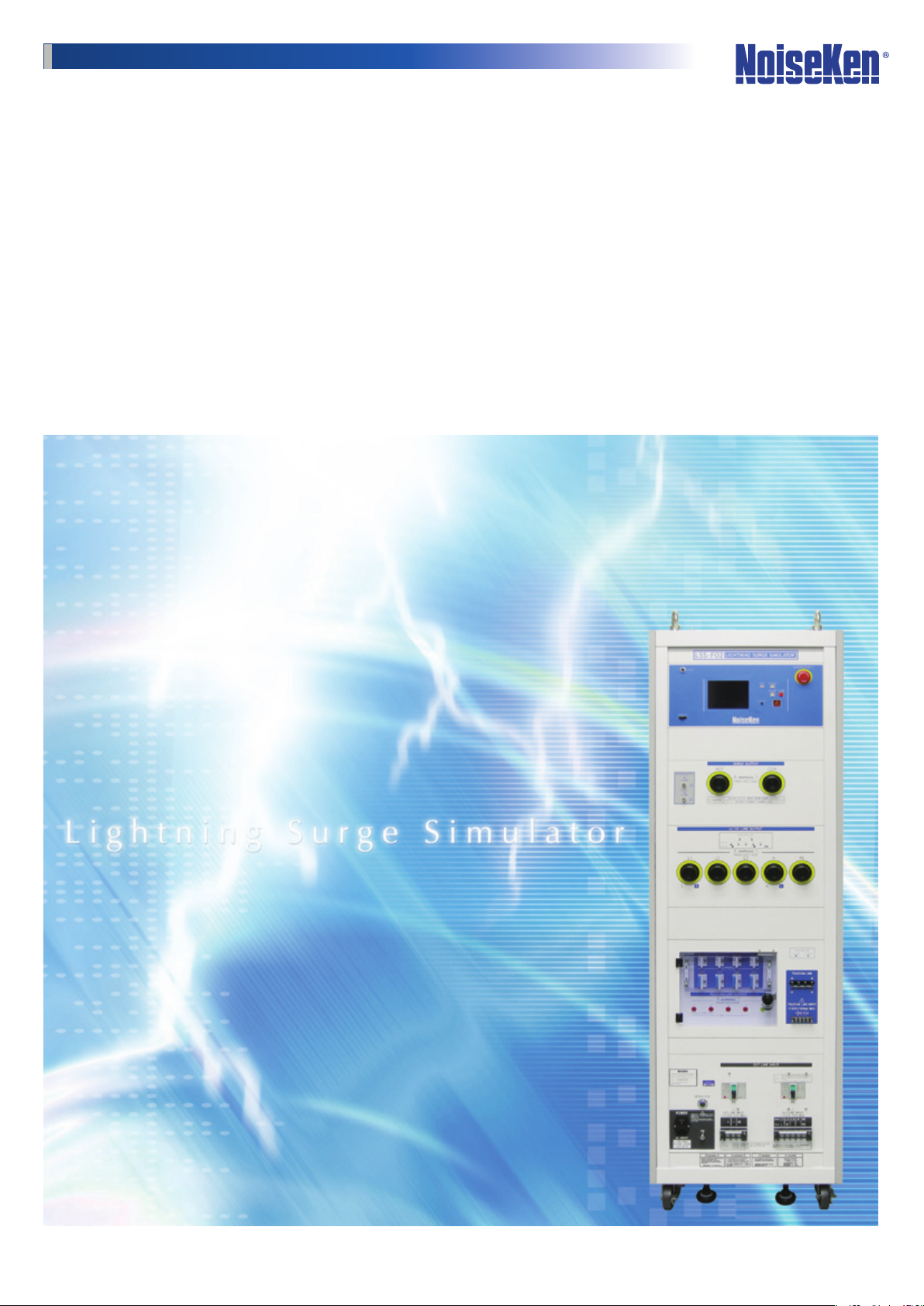
A simulator to reproduce “High energy induced lightning noise” which is induced by potential change on the ground, or done
to power lines or telephone lines as result of lightning current.
Dedicated to evaluate performance of electronic equipments which are connected to power lines and telephone lines come
from the outdoors or interconnection lines between buildings and the others or the oors and the other oors whether the
equipments may be malfunctioned, deteriorated or resistible.
Noise inow image into a residence
Test setup to consumer appliances
Noise inow image into a factory
Test setup to industrial equipments
Test setup to electronic components
Test setup to automotive devices
Page 3

www.noiseken.com
3
●
≥ 4kV
< 4kV
Unknown
0
Previous
models
LSS-F02
5 10 15 20 25
(sec)
Repetition cycle
Reduced
Feature of LSS-F02 : "More safety, reliable and easy test realized"
●
"Output voltage 15kV, current 7500A"
which can conduct breakdown resistibility test
Approx. 60% of the users are carrying on the test with
voltage more than IEC Standard.
Requirement in IEC Standard < To keep up
with quality in the market
Test voltage of lightning surge immunity test
Quoted from the market investigation by NoiseKen on 2010
"50% reduction of the output interval"
which can drastically reduce the test time
Realize 1/2 of the interval time comparing to our previous
models so as to contribute to reduction of the man-hour for
the test.
(* in case of the test less than 6kV output)
"Touch-panel"
adopted for the easy test setting
Adopt LCD touch panel for pursuing high visibility and
realizing user-friendly operation with afuent icons.
Also, easy operation is realized not only for the test
according to IEC Standard but also for the sequential tests
with the parameter sweep function.
"Multi-languages"
for the easy operation processing available
Not only Japanese and English but also Chinese and
Korean available for the easy operation processing.
Japanese
Chinese
English
Korean
Page 4

www.noiseken.com
4
●
Powered condition of
EUT ON/OFF selectable
Interlock terminal
Emergency stop switch
ch1 ch2
Oscilloscope
Feature of LSS-F02 : "More safety, reliable and easy test realized"
●
"Indicator"
which is linked with the test setting equipped
Indicators which visualize the cables connections in the test
equipped.
"Emergency stop" & "Interlock terminal"
PC control available with the
optional software
Enable to control from external Windows PC. Also, enable
to put the report of the test result in record out.
"Output waveform monitor terminal"
which secure the test operator equipped.
Emergency stop function which takes safety of the test
operator into the account equipped both in the main body
and the software. Also, the interlock setting and output
voltage control function equipped.
If the protective safety fence and protective safety box are
adopted as the options, more safety test can be realized.
which can ease pre-checking of the waveforms prior to the actual test
In order to respond to the request "The simple waveform
checking is desired before the test", equip the monitor
terminal.
* The terminal is just for the simple checking.
If the accurate measurement is required, the specialized
equipments are necessary.
Please contact us for the more details.
Page 5

www.noiseken.com
5
Specification
LSS-F02-
□□
How to understand the model numbers
A : 1.2/50μs-8/20μs (Totally 1 kind surge generates)
C : 1.2/50μs-8/20μs、10/700μs-5/320μs (Totally 2 kinds)
1 : Model for single phase EUT L/N/PE
3 : Model for 3-phase EUT L1/L2/L3/N/PE(Available both for single phase & 3-phase)
Parameter
Specication
Surge generating unit
1.2/50μs-8/20μs
Combination waveforms
10/700μs-5/320μs
Combination waveforms
Output voltage
Front time
Duration
Output current
Front time
Duration
Output voltage
Front time
Duration
Output current
Front time
Duration
Output polarit y Positive / Negative
Interval
Output impedance
40Ω ±10%
2Ω ±10%
10 sec.~989 sec., depending on the set voltage 10 sec. (< 6kV
AC/DC CDN
Coupling surge waveform
1.2/50μs-8/20μs combination waveforms
Max. coupling surge voltage / current Up to the values which can be set
Coupling network
Correspondent to IEC61000-4-5
Injection mode
18μF
10Ω ±9μF
Between LINE - LINE, Between LINE - PE
Power supply lines structure for EUT Single phase AC
DC
DC
EUT power capacity
AC500V/50A MAX 50/60Hz、DC125V/50A MAX
Decoupling coil
Phase angle control
AC240V/20A MAX 50/60Hz、DC125V/20A MAX
1.5 mH
0
3-phase AC
~
CDN for Telecom lines (Only in model C1 and C3)
Coupling surge waveform
Max. coupling surge voltage / current
Impedance matching resistors
25Ω
Coupling mode
Coupling network
Line for EUT
Decoupling coil
20mH
1.2/50μs-8/20μs combination waveforms
10/700μs-5/320μs combination waveforms
40Ω
Common mode / Normal mode
Gas arrestor : 90V
2 lines / 4 lines DC50V/100mA MAX
Others
Voltage monitor
Current monitor
External communication
Power supply
Dimension
Mass
AC100V~AC240V ±10% 50Hz / 60 Hz
W555×H1800×D790 mm
BNC output, 1/2000±10%
BNC output, 1mV/A±10%
RS-232C optical communication
Approx. 300kg
Approx. 340kg
0.5kV~15kV ±10%
1.2μs ±30%
50μs ±20%
250A~7500A ±10%
8μs ±20
20μs ±20
0.5kV~15kV ±10%
10μs ±30% Models:C1/C 3
700μs ± 20%
12. 5A~375A ±10%
5μs ±20
320μs ± 20
%
%
%
%
Between LINE - LINE (10Ω +9μF selectable)
Between LINE - PE (18μF selectable
L/N/PE
:
+/-/PE
360° ±10°
:
:
L1/L2/L3/N/PE(Common for single phase and 3-phase)
+/-/PE
:
Up to the values which can be set
80Ωper 1 line at 2 lines
160Ωper 1 line at 4 lines
0Ωper 1 line at 2 lines
5
100Ωper 1 line at 4 lines
●
LSS-F02 series specication
●
Note
Common for the all models
Voltage step : 0.1kV step
The setting can be from 0kV
Voltage step : 0.1kV step
The setting can be from 0kV
)
15 sec.~ in 10/700μs waveform
1.2/50μs waveform
10/700μs waveform
)
Model : A1 / C1
Model : A3 / C3
Model : A1 / C1
Model : A3 / C3
1.2/50 μs waveform
10/700 μs waveform
Selectable
In open-circuit for SURGE OUT
In short-circuit for SURGE OUT
Projection excluded (in all models)
Model : A1 / A3
Model : C1 / C3
Standard accessory
Item Specication / Function Q'ty Correspondent model
Surge output cable HOT / COM 2 pcs. Common
Output cable to power supply lines For single phase : L / N / PE 3 pcs. A1/C1
For 3-phase : L1 / L2 / L3 / N / PE 5 pcs. A3/C3
Output cable to telecom lines For 1~4 lines and GND 5 pcs. C1/C3
Arrestor unit For coupling : Equipped to main unit panel 4 pcs. C1/C3
For input protection : Equipped to main unit panel 4 pcs.
Cable for monitor BNC-BNC cable 1 pc. Common
External interlock connector 5P plug (Short between #1 - #3) 1 pc. Common
Power supply cable For AC100V, 3P equipped with G connector cable 1 pc. Common
High voltage connector cap Equipped to main unit panel 5 pcs. A1/C1
7 pcs. A3/C3
FG cable For grounding the body 1 pc. Common
Instruction manual
These products use parts containing mercury. Please comply with lows or regulation in countries or states the products are used for the disposal.
●
Certain periodical inspection shall be recommended since consumable parts are contained in the products.
●
In the test to 3-phase 5 lines (with PE) power supply lines, a message which alert the inspection per around 200 sets (in the test to single phase (with PE) power supply lines, it is done per around 800 sets).
(1 set in this case means that the test shall be done with 2 levels (eg. 0.5kV and 1kV) for the test series according to IEC61000-4-5)
* Exchange timing of the parts may differed depending on the operative conditions and environment. Please contact us for the more details.
1 volume Common
-
Page 6

www.noiseken.com
6
Option
ch1
ch2
Surge generator
High voltage probe X 2 pcs.
Connect GND of high voltage probe
Grounding
conductor
Isolation
transformer
PE noncontact
Power supply
HOTch1ch
2PECOMSurge
Oscilloscope which
enables differential
measurement
CDN for Interconnection Lines
Used for the surge test to interconnection lines dened in
IEC61000- 4-5 Standard. The EUT power capacity is DC50V/1A
and enable to inject the surge to interconnection lines up to
6,600V. Possible to bypass inductor (20mH) with connecting
the attached connection plug to inductor bypass terminal in
DC output. Possible to equip the attached surge protective
arrestor between each line and ground.
* The conversion (05 -H1784)cable is needed additionally.
* Both capacitor coupling and arrestor coupling are possible in LSS-INJ6400SIG. Diode coupling which is d ened in IEC61000-4-5 ed.2 (2005) newly
is a test met hod which assumes the injection of dozens of voltage level surge to interconnection lines. Pl ease contact us if low voltage surge in jection is
required since t he surge injecti on in LSS-INJ64 00SIG ca n be more than 90V.
Isolation Transformer
Warning Lamp
MODEL:TF-2302P
Maximum capacity is single phase AC240V / 30A
and the dielectric strength is 4kV
Available for AC lines power supply in LSS-F02
series and widely usable for the other various noise
generators or measurement equipments.
Parameter Specication
Max. in put voltage
Max. output volt age 30A MAX
Dielec tric strength
Secondary to core : AC4kV (1 minute)
Primary – Sec ondary : AC4kV (1 minute)
Insulation resistance ≧100MΩ at DC500V
Dimension / Mass (W)350×(H)475×(D)400mm
(Eye bo lts and handle s exclude d)
Approx. 60 kg
MODEL:11-00008A
Usable together with LSS-F02 series. The blinking
makes the operators or neighbors pay attention to the
test processing.
MODEL:LSS-INJ6400SIG
Single p hase 240V MA X (50 / 60Hz)
Primar y to core : AC4kV (1 minute)
Parameter Specication
Surge input voltage 500V~6.600V (Combination wave)
EUT power capacit y DC50V/1A
Max. line number 4 lines
Decoupling coil 20mH eac h line
Impeda nce matc hing resistor 40Ω ±10%
Dimension / Mass ( W)488×(H)456×(D)550mm Ap prox. 45kg
Isolation Transformer
MODEL:TF-6503P
Maximum capacity is 3-phase AC600V / 50A and
the dielectric strength is 4kV
Available for AC lines power supply in LSS-F02
series and widely usable for the other various noise
generators or measurement
Parameter Specication
Max. in put voltage
Transformer connection
Max. output volt age 50A MAX
Dielec tric strength
Secondary to core : AC4kV (1 minute)
Primary – Sec ondary : AC4kV (1 minute)
Insulation resistance ≧100MΩ at DC500V
Dimension / Mass (W)500×(H)64 0×(D)700mm
(Eye bo lts and handle s exclude d)
Approx. 350 kg
Protective Safety Fence
MODEL:11-00010A
Single p hase / 3-hase 240V MAX (50 / 60Hz)
Y-connection
Primar y to core : AC4kV (1 minute)
Enable to materialize the safe test environment
with connection to interlock function equipped in
LSS-F02 series. The safety measure can be sure
together with the EUT protective safety box.
Waveform Pre-Checking Cables Set
Fixtures for checking voltage waveforms and current
waveforms of LSS-F02 series.
Followings are necessar y for the checking additionally.
・Oscilloscope (Differential operation function built-in)
・High voltage probes (for surge voltage measurement /
Voltage resistibility necessary)
・Current prob e (For surge shor t current measurement)
・Isolation transformer (for oscilloscope)
・Ear th cable (for PE connection)
MODEL:05-00099A
Optical USB module
MODEL:07-00022A
Optical conversion adaptor Used for remote control
with PC. 5m of optical ber cable with USB interface
attached.
EUT Protective Safety Box
MODEL:11-00005A/11-00006A
Protection box to prevent access to EUT during the
test.
Further safety is secured together with the safety
protective fence
Terminal Connection Board attached with Multi-Outlet (3p)
MODEL:18-00048B
Relay terminal board to connect output of LSS-F02
series to EUT. Enable to connect any outlet gure in
the world when wiring to the attached multi-outlet.
For single phase 3 lines (Voltage resistible capacity
4.5kV)
* The same option for 3-phase 5 lines also available
(18-00058B)
Page 7

www.noiseken.com
7
Reference
U High-voltage source
Rc Charging resistor
Cc Energy storage capacitor (20μF)
Rs Pulse duration shaping resistors
Rm Impedance matching resistor
Lr Rise time shaping inductor
Cc
Rc Rm
Rs
1
Rs
2
Lr
U
U High-voltage source
Rc Charging resistor
Cc Energy storage capacitor (20μF)
Rs Pulse duration shaping resistor
Rm Impedance matching resistors (Rm1=15Ω:Rm2=25Ω)
Cs Rise time shaping capacitor (0.2μF)
S1 Switch closed when using external matching resistors
Cc Cs
Rc
Rm
1
Rm
2
S1
Rs
U
Front time : T1=1.67×T=1.2μs ±30%
Time to half-value : T
2
=50μs ±20%
T
1
T
2
T
t
30% max.
0.0
0.3
0.5
0.9
U
1.0
A
Front time : T1=1.67×T=10μs ±30%
Time to half-value : T
2
=700μs ±20%
T
1
T
2
T
t
0.0
0.3
0.5
0.9
U
1.0
A
Front time : T1=1.25×T=8μs ±20%
Time to half-value : T
2
=20μs ±20%
T
1
T
2
T
t
30% max.
0.0
0.3
0.1
0.5
0.9
U
1.0
1.0
I/Imax
O1
T2
T2
T
t
0.9
0.5
0.1
0.0
Front time : T1=1.25×T=5μs±20%
Time to half-value : T2=320μs±20%
Summary of IEC61000-4-5 ed2.0 Standard
1. General
The task of the described laboratory test is to nd the reaction of the EUT under specied operational conditions, to surge
voltages caused by switching and lightning effects at certain threat levels. This standard species 2 kinds of the combination
waveforms. One is simulating the injection to power supply lines and interconnections lines (The voltage waveform as 1.2/50μs
and current waveform as 8/20μs) and the other is doing the injection to telecommunications lines (The voltage waveform as
10/700μs and current waveform as 5/320μs).
It is not intended to test the capability of the EUT’s insulation to withstand high-voltage stress, direct injections of lightning
currents, i.e., direct lightning strikes, are not considered in this standard.
2. Test Level
Level Open-circuit test voltage±10% (kV)
1 0.5
2 1.0
3 2.0
4 4.0
x spec ial
* X can be any level determined by consent between the EUT manufacturer and
the simulator supplier
3. Waveforms Generator and Waveforms verification
1.2 / 50 Combination Waveform (1.2/50 - 8/20μs) Generation Circuit
■
Voltage Surge (1.2/50μs)
■
Current Surge (8/20μs)
■
10 / 700 Combination Waveform (10/700 - 5/320μs) Generation Circuit
■
Voltage Surge (10/700μs)
■
Current Surge (5/320μs)
■
Page 8

* Designs and specifications are subject to be changed without notice.
International Sales & Marketing Section
TEL : +81-(0)42-712-2051/FAX : +81-(0)42-712-2050
E-mail : sales@noiseken.com
1-4-4 Chiyoda, Chuo-ku, Sagamihara City, Kanagawa Pref. 252-0237 Japan
URL : http://www.noiseken.c om
1012-02K-H
Noise Laboratory Co., Ltd.
Voltage waveform specication at the EUT port of the coupling/decoupling network
Wooden table
EUT
SURGE OUT
LINE OUT
Isolation transformer
AC
PE
Surge generator
SURGE OUT
LINE OUT
Isolation transformer
Wooden table
AC
PE
Surge generator
TEL LINE OUT
EUT
Surge voltage parameters under open circuit conditions
Front time
Time to half value
Current rating < 25 A
Current rating 25 A – 60 A
Current rating 60 A – 100 A
NOTE The measurement of the surge voltage parameters should be done with the power supply input port of the coupling/decoupling network open-
1.2μs±30% 1.2μs±30%
50μs+10μs/-10μs 50μs+10μs/-25μs
50μs+10μs/-15μs 50μs+10μs/-30μs
50μs+10μs/-20μs 50μs+10μs/-35μs
Coupling impedance
18μF 9μF+10Ω
circuit.
Current waveform specication at the EUT port of the coupling/decoupling network
Surge current parameters under short circuit conditions
Front time
Time to half value
NOTE The measurement of the surge current parameters should be done with the power supply input port of the coupling/decoupling network open-circuit.
8μs±20% 2.5μs±30%
20μs±20% 25μs±30%
Coupling impedance
18μF 9μF+10Ω
4. Test Setup
Injection to power supply lines
■
Injecting 1.2/50 combination wave put out from CDN of
LSS-F02 to battery drive of a PC.
Floating circuit is adapted according to the Standard for
the output.
In LSS-F02 series, enable the automated operation with
the program function along the above gure.
Injection to telecom lines and power supply lines
■
Injecting 1.2/50 combination wave and telecom surge
(10 / 7 0 0 combinat i o n wave) p u t o ut from CDN of
LSS-F02 to power supply lines and telecom lines of a
fax machine.
In LSS-F02 series, enable the automated operation with
the program function along the above gure.
* The above setup gure is one example of the test setup our lightning surge simulator.
There is no specication on the Standard.
 Loading...