

Page 1
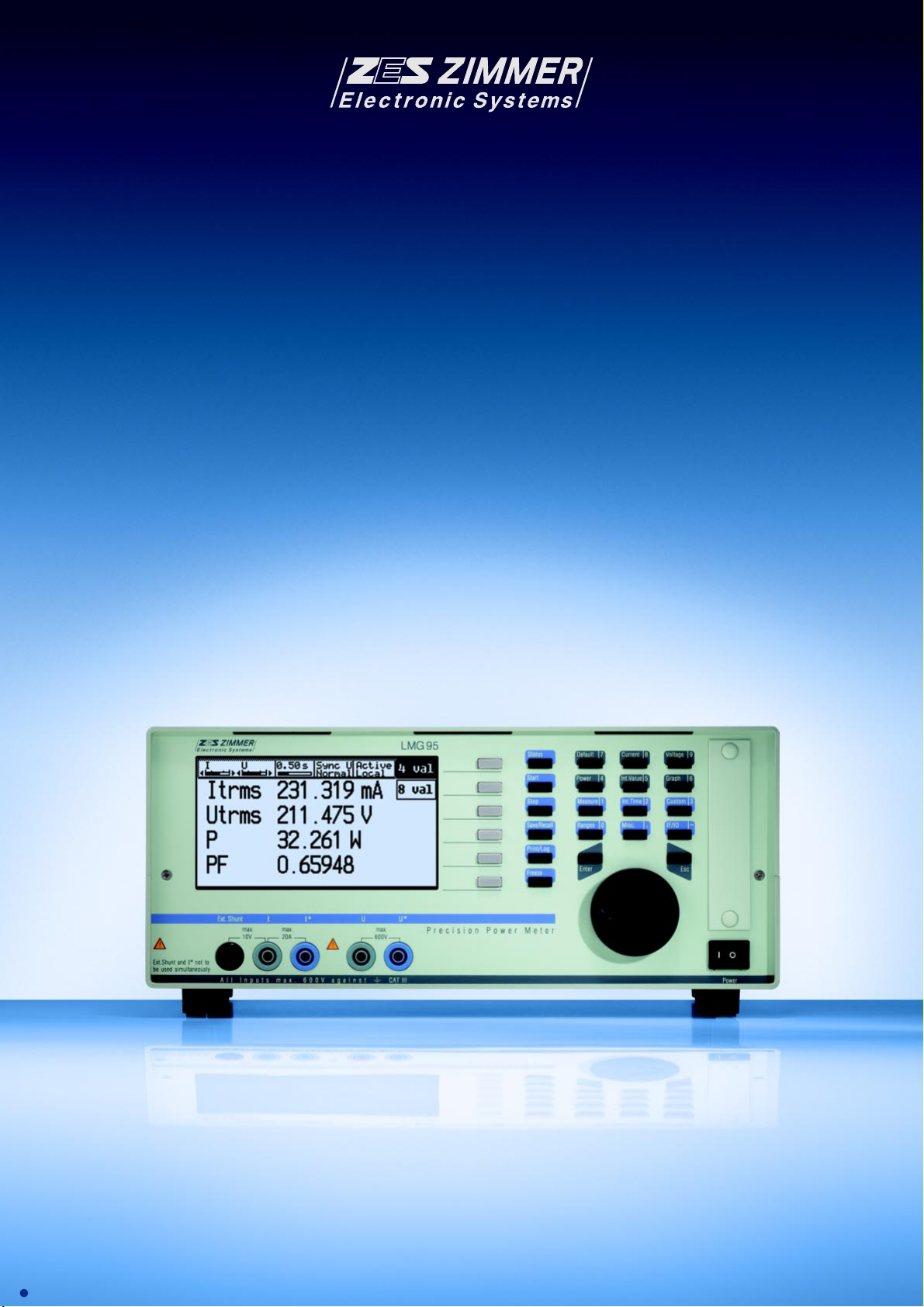
Precision Power Meter LMG95
Basic Accuracy 0.03% Precision Range DC...500kHz
Analysis of Devices and Components
in Switched or Modulated Operation
EN61000-3-2/3 Analyser for Harmonics and Flicker
LMG95 e 08.02
LMG95
Page 2
LMG95. Precise. Direct. All Waveforms. Transparency Throug
The LMG95 single-phase precision power meter is an
outstanding product in the LMG Series of proven
ZES ZIMMER precision power measuring devices.
Highly accurate continuous and gap-free signal
measurement and processing, ergonomic operation and
presentation of the results, interfaces with high data
rates for efficient system applications – these are the
performance features which distinguish the LMG95.
All Waveforms
The high precision power measurements on components
and devices wanted in development, quality
assurance and manufacturing can be performed
with ease – independent of whether or not the current
and voltage are sinusoidal or distorted, whether the
load is linear or not, or whether the circuit works in a
chopped, pulsed mode or in a modulation mode.
Extended possibilities of synchronisation on the
periodicity of the signal measured always produce
distinct and stable measurement displays and results.
Direct Up to 600V and 20A
Isolated measurement inputs with direct measurements
ranges up to 600V (1600Vpeak) and 20A (960Apeak for
the measurement of inrush currents) and the input for
current measurements using a shunt or other transducer
measure the incoming measurement signals exactly and
without any aberrations.
0.03% Accuracy
With a basic accuracy of 0.03%, this is the most
precise instrument in its class and it is therefore used
as a reference device for power meters, power
measurement transformers and trms-meters for
current and voltage.
Harmonics and Flicker in Full
Compliance With EN61000-3-2/-3
The harmonic analysis in full compliance with the
EN61000-3-2 standard is already available in the basic
unit. The flicker meter in compliance with EN61000-4-15
for the measurement of flicker (voltage variations) is
available as an option. These two functions considerably extend the possible applications of the LMG95 in
the laboratory area as well. If suitable stable voltage
sources are available, tests for CE compliance can be
performed in accordance with EN61000-3-2/-3.
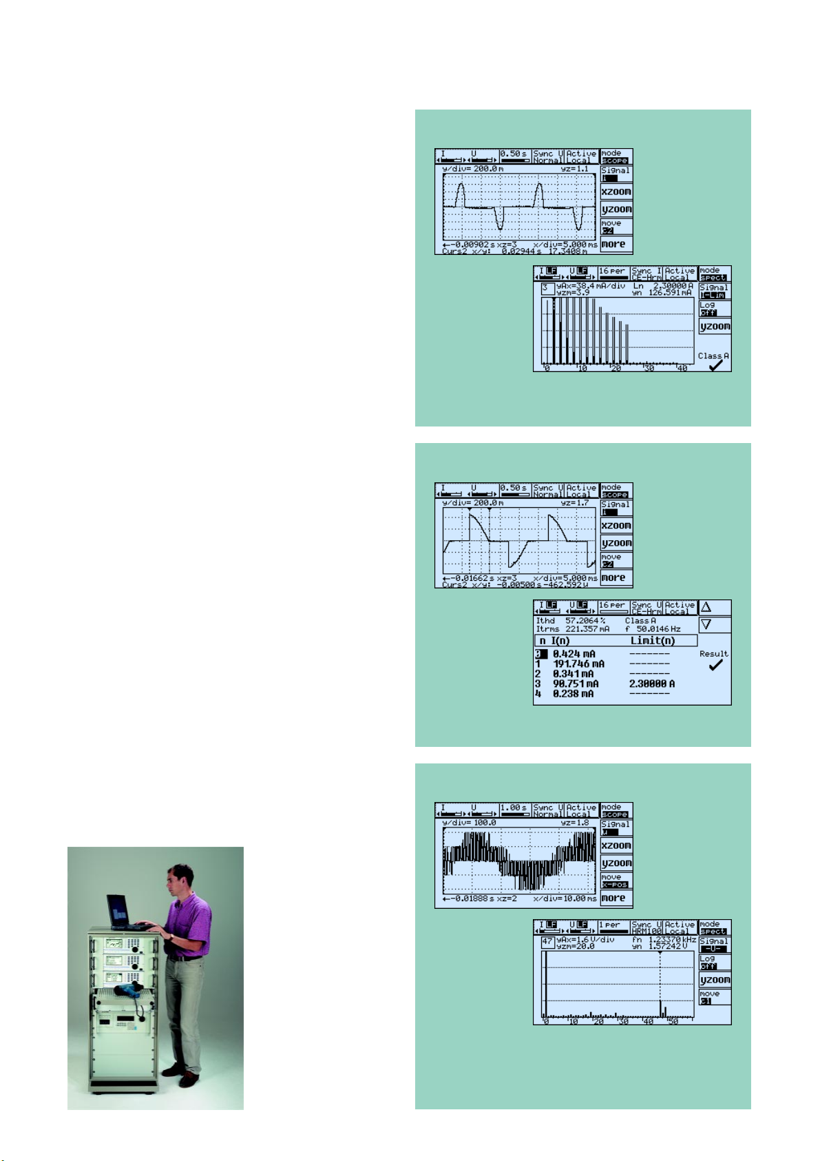
Charging current of a switching power
supply
Waveform of
charging current
Amplitude spectrum of the current
harmonics with CE evaluation in
accordance with Class A
Phase-angle control
Waveform of
current
Table of the current harmonics with
limits in accordance with Class A
PWM frequency inverter
Analysers in CE Test Systems
The LMG95 is used
as an analyser in
CE test systems to
test electrical devices on harmonics
and flicker and
their effect on
mains – for example
it is used in the ZES
ZIMMER SYS61K
test system shown
in the adjacent
illustration.
In 3-phase applications three LMG95
units are used.
Line voltage
against artificial
midpoint
Measurement of the amplitude spectrum of the voltage harmonics in the
HRM100 mode. An increase in the 47
and 49th, the frequency of the fundamental amounts to fn/47=26.25Hz
th
Page 3
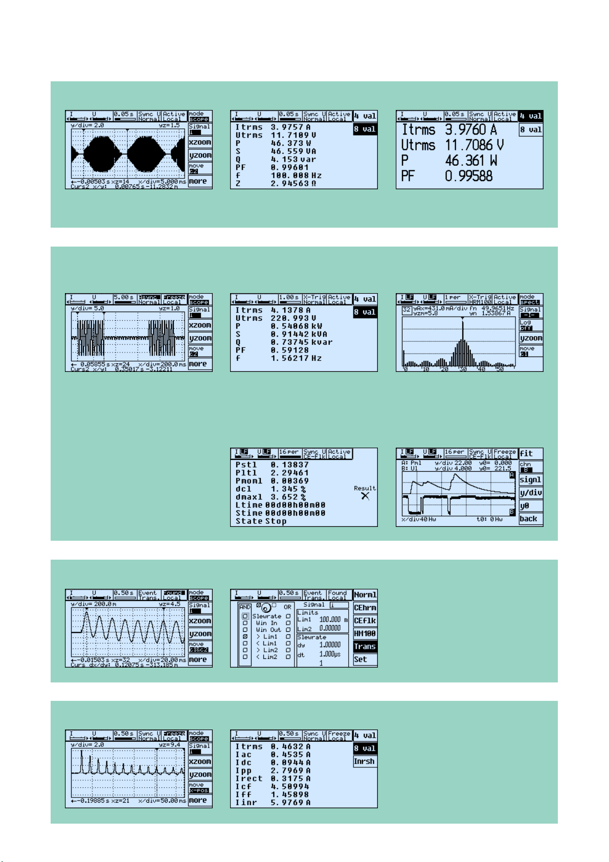
Electronic transformer
Electronic 12V transformer to supply a halogen lamp.
Amplitude modulated 150 kHz carrier with 100Hz envelope.
Burst firing control of a hot-air fan
Harmonic analysis
Amplitude spectrum with the help of the HRM100 harmonic analysis. The burst fire presents a 1.56Hz modulation of the carrier
(50Hz mains voltage). The DC component of the spectrum results from the blower motor in half-wave operation.
The extended “X-Trig” trigger mode detects the 1.56Hz periodicity which is used for synchronisation.
Flicker measurement
Using the plot function the halfwave trms values U
time (lower curve B).
Irregular sags of about 8V can be
recognised. The momentary flicker
Pmom resulting from these changes
is visualised in Curve A.
l are plotted over
Switch-on current of a fluorescent lamp ballast measured in the transient mode
Switch-on current of a fluorescent
lamp ballast.
The iron is not saturated.
Inrush current of a transformer
In the moment when the currentless,
non-magnetised transformer is
switched on a multiple of the nominal
current is required to build up the
necessary flux. The iron goes rapidly
into saturation. Here Iinr/Itrms=12.9.
Page 4

Graphical display
Real-time visualisation, 4 or 8 measured values, measured signals in the time and frequency domain:
• You see the signals which you measure • You can estimate whether the measurement is running correctly • You discover new
things depending on current, voltage and power • You better understand the dependencies of the components in the circuit
Core losses at small cos
ϕϕ
ϕ
ϕϕ
and high frequencies
(with optional 500kHz precision band
width and delay compensation to 4ns)
I
˜
U
The magnetising current I flowing in the primary winding is fed into the current input of the LMG95, and the induced voltage at
the open secondary winding is fed into the voltage input. In this way, only the core losses (magnetising losses) are measured,
and not the copper losses. The half-wave rectified voltage value, also measured with the LMG95, is a measure of the voltage
time area, and therewith for the induced flux. With the formula editor, the values for a B-H characteristic curve can be calculated from the measured electrical values and the geometrical data of the core.
Device settings
Up to 8 device settings can be stored with name, datas of the test sample, etc.,
with “Save” and called up again with “Recll”.
A high level of user convenience if measurements should be made alternatively on
different samples.
Technical data
Voltage measuring ranges
Rated Range value /V 6 12.5 25 60 130 250 400 600 Also available with ranges:
Permissible trms value /V 7.2 14.4 30 60 130 270 560 720 25mV...3mV,
Permissible peak value 12.5 25 50 100 200 400 800 1600 100mV...12V
for full scale /V 400mV...60V
Overload capability 1500V for 1s 12V...650V (3200Vpk)
Input resistance 1MΩ, 20pF
Current measuring ranges
Rated range value /A 0.15 0.3 0.6 1.2 2.5 5 10 20 120 240 480 960 Also available with ranges:
Permissible trms value /A 0.3 0.6 1.3 2.6 5.2 10 21 21 21 21 21 21 0.6mA...80mA
Permissible peak value 0.469 0.938 1.875 3.75 7.5 15 30 60 120 240 480 960 10mA...1200mA
for full scale /A 40mA...5A
Overload capability 160A for 1s
Input resistance 5mΩ
Voltage inputs for current measuring
with shunt / transducer
Rated range value /V 0.03 0.06 0.12 0.25 0.5 1 2 4
Permissible trms value /V 0.06 0.13 0.27 0.54 1 2 4 8
Permissible peak value 0.0977 0.1953 0.3906 0.7813 1.563 3.125 6.25 12.5
for full scale /V
Overload capability 250V for 1s
Input resistance 100kΩ
Measuring range selection Auto, manual or remote controlled
Isolation Current and voltage path are isolated against each other and may float against earth with 600V. Testing voltage 3250V
Measuring method Simultaneous sampling of the current and voltage inputs and A/D conversion of the instantaneous values (100kHz).
Measuring cycle, synchronization, For measurements of the trms values for current, voltage and active power the measuring cycle time is adjustable in the range
averaging of 50ms to 60s. The synchronization can be performed on the measuring signal, the fundamental harmonic, the envelope, the
Measuring accuracy (Standard version)
Memory for up to 2.106 sampling values.
mains or an external signal. Single measurings with stop after one or more cycles are possible, averaging over 1 to 16 cycles.
gnirusaeM
ycaruccA
CD zH51...50.0 zH54...51 zH56...54 zHk1...zH56 zHk3...1 zHk51...3 zHk05...51
)egnargnirusaem%+eulavgnirusaemfo%(±
egatloV 60.0+20.0 40.0+20.0 30.0+510.0 20.0+10.0 30.0+510.0 60.0+30.0 2.0+1.0 0.1+5.0
tnerruC 60.0+20.0 40.0+20.0 30.0+510.0 20.0+10.0 30.0+510.0 60.0+30.0 2.0+1.0 0.1+5.0
egatloVtnuhS
tupnI
rewoPevitcA 60.0+30.0 40.0+530.0 30.0+520.0 20.0+510.0 30.0+520.0 60.0+50.0 2.0+2.0 0.1+0.1
60.0+20.0 40.0+20.0 30.0+510.0 20.0+10.0 30.0+510.0 60.0+30.0 2.0+1.0 0.1+5.0
Page 5

Measuring accuracy (500kHz version)
ϕϕ
ϕ
Measuring accuracy of cos
ϕϕ
gnirusaeM
ycaruccA
CD zH51...50.0 zH54...51 zH56...54 zHk1...zH56 zHk3...1 zHk51...3 zHk001...51 zHk002...001 zHk003...002 zHk004...003 zHk005...004
egatloV 60.0+20.0 40.0+20.0 30.0+510.0 20.0+10.0 30.0+510.0 50.0+520.0 60.0+30.0 2.0+1.0 0.1+5.0 0.2+0.1 0.3+0.3 0.4+0.4
tnerruC 60.0+20.0 40.0+20.0 30.0+510.0 20.0+10.0 30.0+510.0 50.0+520.0 60.0+30.0 2.0+1.0 0.1+5.0 0.2+0.1 0.3+0.3 0.4+0.4
egatloVtnuhS
tupnI
60.0+20.0 40.0+20.0 30.0+510.0 20.0+10.0 30.0+510.0 50.0+520.0 60.0+30.0 2.0+1.0 0.1+5.0 0.2+0.1 0.3+0.3 0.4+0.4
rewoPevitcA 60.0+30.0 40.0+530.0 30.0+520.0 20.0+510.0 30.0+520.0 50.0+40.0 60.0+50.0 2.0+2.0 0.1+0.1 0.2+0.2 0.3+0.6 0.4+0.7
)egnargnirusaem%+eulavgnirusaemfo%(±
Accuracies based on 1. sinusoidal voltage and current 4. definition of power range as the product of
2. ambient temperature 23 °C current and voltage range, 0 ≤ IλI ≤ 1
3. warm up time 1h (λ=Power factor=P/S)
5. calibration interval 12 month
Other values All other values are derived from the values for current, voltage and active power. Accuracies for the derived values depends on
the functional relation (e.g. S = I * U, ∆S/S = ∆I/I + ∆U/U)
Internal time base
±
25ppm at 23°C
Frequency measuring 0.05Hz...500kHz ±0.01% of measuring value, measuring channel selectable.
Display of measured and computed values
Representation With standard abbreviation of measured magnitudes, numeral values 6 digits (0...999999), with sign, decimal point and unit
(e.g. Itrms 0.73851mA), 1 to 8 values can be displayed simultaneously, selectable via default or user defined menus
Voltage/current trms value, peak values (min, max, pp), rectified value (rect), mean value (dc), trms value of ac component (ac),
form factor, crest factor
Power Active power (P), reactive power (Q), apparent power (S), phase angle (ϕ), power factor (λ)
Impedance Amount (Z), real- und imaginary part of resistor in serial equivalent circuit
Integrated values depending on The integration can be controlled manually, automatically using start and stop times, via external trigger or remote
the measuring time controlled via computer interface
Energy, Charge active energy (Ep), reactive energy (Eq), apparent energy (Es), charge (q)
Date and time, measuring time current date (day, month, year) with time (hour, minutes, seconds), accu buffered real time clock, start time for measurement,
running measuring time, on-time, each with days, hours, minutes, seconds
Adjustable parameters Scaling factors for external shunt, current and voltage transducer
Synchronisation Synchronisation is made on the periodicity of the measured signal. Periodicity can be determined by the signals u(t), i(t), p(t),
u²(t), i²(t), each of them can be adapted with selectable filters. By this stable displays also with pulse width modulated signals
(e.g. frequency inverter) and amplitude modulated signals (e.g. electronic ballast). Synchronization also by „Line“ and „External“
Scope function Graphical representation of sampled values (waveform of the signal)
Plot function Time diagram of calculated values, e.g. trms value and power
Harmonic analysis CE-Hrm Analysis of current and voltage up to the 40th harmonic (total of 41 with DC component), fundamental in the range
45Hz to 65Hz. Analyser in accordance with EN61000-4-7 with evaluation in full compliance with EN61000-3-2
Harmonic analysis HRM100 Analysis of current, voltage and effective power up to the 99th harmonic (total of 100 with DC component), fundamental in the
range 0.1 Hz to 1.2 kHz; with adjustable divider (1...50), a new fundamental can be set as a reference, for example to
determine interharmonics
Flicker measuring Flicker meter in accordance with EN61000-4-15 with evaluation in accordance with EN61000-3-3
Transients – monitoring and storing Storing and graphical displaying of transients with a resolution of 10µs. Storing depth is 4 Millions sample values,
selectable recording duration from 0.05 to 60 seconds. Adjustable pre-trigger, different possibilities of triggering
Computer interface Interfaces: RS232 and IEEE488.2, only one interface can be used at the same time
Remote control All functions can be remote controlled
Output data Output of all displayable data possible, data formats of all interfaces are the same, SCPI command set
Transfer rates RS232: max. 115200 Baud, IEEE488.2: max. 1MByte/sec
Printer interface Parallel PC-printer-interface with 25 pin SUB-D socket
for printing of values tables and graphics on needle, ink or laser printer
Memory modul For PCMCIA memory cards, data logging of measuring and sample values
Processing signal interface 25 pin SUB-D socket:
4 analog inputs for registration of auxiliary quantities (16bit, ±10V)
4 analog ouputs for output of any measured or computed values in real time (16bit, ±10V)
4 digital inputs for registration of status
4 digital outputs to signal states and alarms
1 input for frequency (0.1Hz...500kHz) and direction (e.g. of motors)
1 power supply output 12V/50mA
Inputs and outputs are isolated group wise against each other and against the other electronics (testing voltage 500V)
Other data
External synchronization/trigger Isolated interface for external control of measurement cycle and integration times, outputs for status signals about the actual measuring
Auxiliary RS232 interface For installing options, firmare and for instrument diagnosis
Auxiliary power supply output +15V/0.4A and -15V/0.2A for external transducers
Dimensions/weight -Desktop case, (w)320mm x (h)147mm x (d)274mm, -19"-cassette 84PU, 3HU, (d)274mm, about 5.5kg
Protection class EN61010 (IEC1010, VDE0411), protection class I, Overvoltage class III
Page 6

Other data
Electromagnetic compatibility IEC61000 (EN61000), EN50081, EN50082
Protection system IP20 in accordance with DIN40050
Operating/storage temperature 0...40°C, -20...50°C
Climatic class KYG in accordance with DIN40040
Power supply 85...264V, 47...440Hz, about 30W
Special versions and designs
Accessories
KR-L95
Calibration Certificate,
traceable to ISO9000
L95-SH-100
Shunt to measure small currents up
to 1A, to be connected to the measuring
socket „Ext. Shunt“ of LMG95.
Customer specific design
LMG95-REF High precision standard,
basic accuracy 0.015%. Traceable with
calibration certificate by PTB (National
Institute of Standards in Germany)
PSU600
Precision current transformer, max. 600A,
ü=1500:1, DC to >100kHz,
accuracy <(0.01%MV+0.005%MR)
L95-Z06
HF-summing current transformer with
burden resistor for current measurements
without effecting measure circuitry,
e.g. at discharging lamps.
L95-Z01
Mounting kit for 19“ rack mounting
PSU600-K3-L95
Adapter-/supply cord to connect the
PSU600 to the measuring sockets „I-I*“
of LMG95.
For currents >50A to 600A
L95-SCAN30
Scanner with internal shunts to measure
15 respectively 30 devices under common
supply. Sequential measuring.
Enhancement of the LMG95 to a multi
channel device
L95-Z09
Measuring sockets on rear side,
e.g. when rack mounted
PSU600-BUR15
Adapter with precision burden and
supply cord to connect the PSU600 to
the measuring socket „Ext. Shunt“.
For currents >1A bis 600A
HST6-1, HST6-2, HST12-1, HST12-2
Precision high voltage devider for 6/12kV.
Single pole isolated high voltage
measuring (-1), dual pole isolated high
voltage measuring (-2). Accuracy:
0.05% (45-65Hz), 0.3% (DC-100kHz)
NDL5 Longtime-data logging to harddisk
for LMG95/450. Communication via
Internet/Ethernet, even when recording
LMG95 Application Software
LVDRV-L95 LMG95 driver for LabVIEW 5.1, for RS232- and IEEE488-interface, with software examples
LWINDRV-L95 LMG95 driver for LabWindows/CVI, for RS232- and IEEE488-interface, with software examples
SYS61K-1-SOFT Controlling-/data logging-/evaluation software for long time test of harmonics and flicker
TERM-L5 Data transfer from LMG95/450 to PC via RS232- and IEEE488-interface, recording as ASCII in Microsoft Excel- (CSV) or ZES-format,
Subject to technical changes, especially to improve the product, at any time without prior notification.
WR-24-230
Inverter 24VDC to 230VAC/50Hz for
supply of LMG instruments
according with IEC61000-3-2/-3 with the LMG95
or in tables with any separator, visualisation in real time of some selectable measurement values
MAS1
U-/I- measuring adapter for devices with
„Schuko“plug (Grounding outlet)
MAK1
U-/I- measuring adapter for devices with
inlet connector (non-heating appliances)
ZES ZIMMER Electronic Systems GmbH
Tabaksmühlenweg 30, D-61440 Oberursel/Ts.
Tel. ++49 6171 628750 Fax ++49 6171 5 20 86
http://www.zes.com e-mail: sales@zes.com
 Loading...