

Page 1
Features:
l
Control for 2 Primary and
4 Auxiliary Devices
l
SEEK & SCAN Functions
l
Automatic Target Overrun Correction
l
Element Saving Limit Setting
l
Fiber Optic Control Lines
l
IEEE-488.2 I/O Port
l
Speed Control
Test Site Hardware
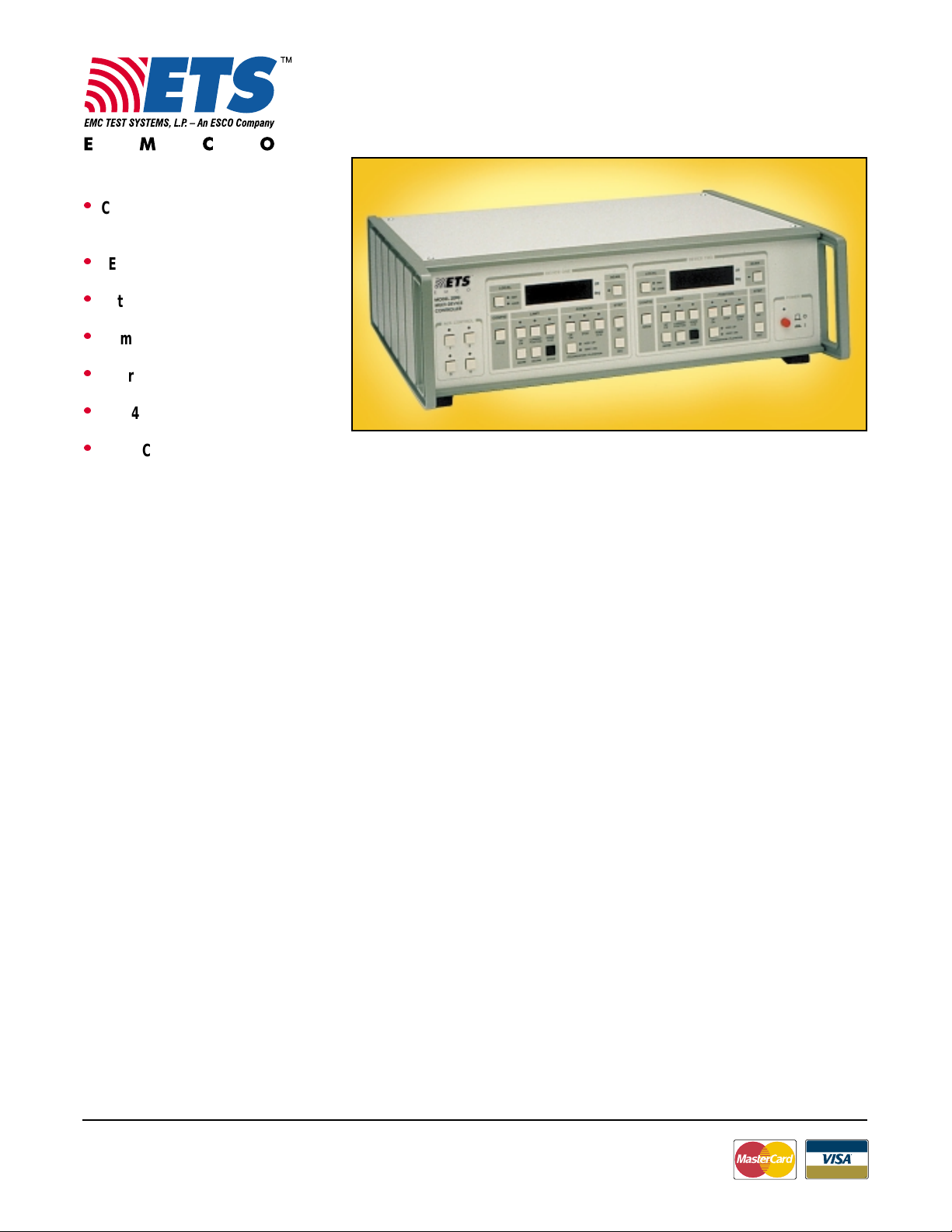
Positioning Controller
Model 2090
Model 2090 Positioning Controller
ETS-EMCO’s Model 2090 P ositioning
Controller allows you to synchronize
simultaneou s movement of two primary
ETS-EMCO devices (towers or turntables), and on/off operation of up to
four auxili ary devices (LISNs, EUTs, et c.).
Indep endent op eration of primary
devices can be performed manually, by
either of the two front panel controls, or
remote ly, by a separat e GP IB ad dress for
each device. Fibe r optic control line s
eliminate RF interference that can be
conducted through traditional wire cables.
The Model 2090 is designed to maximize
the features of ETS-EMCO antenna
towers and turntables. See page 4 for
information about retrofits to earlier ETSEMCO models and non-ETS products.
Functions
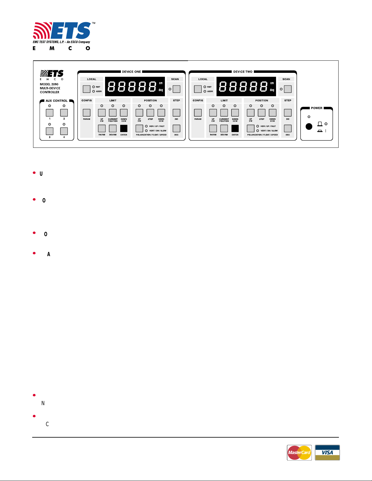
The front panel de sign o f the Model 2090
features a user-friendly int erface which
simplifies device control and clearly
communicates primary device movement
to the operator. Two separate sets of
controls (Device One and Device Tw o),
eac h wi th i de n ti cal di sp l a y s a n d fun cti o n s ,
are included. Other front panel feature s
include four auxiliary control switches and
the Model 2090 pow er swit c h.
A number of useful primary device
commands can be performed by the
operator. The SEEK function enables the
user to reposition a device to a new
target location and the SCAN com mand
initiates cyclic movem ent of a device.
The CONFIG and LIMIT functions
enable the user to p r o gram operational
parameters and upper/lower or clockwise/counte rclockwise limits for each
device. The POSITION and STEP
functions work together to control to wer
cross boom and/or turn ta ble posi ti oning.
Expanded details of these functions are
offer ed be low.
SEEK & SCSEEK & SC
SEEK & SC
SEEK & SCSEEK & SC
ANAN
AN
ANAN
SEEK allows a target location to be
entere d to redirect the device from its
current location. Target locations can be
automatically incremented/decremented
by a given value. The SEEK command is
available o nly through the GPIB. All other
functions can be performed from both
the GPIB and the front panel. The SCAN
key initiate s cyclic movement of a device
between pre-progr ammed lim its. A cycle
is defined as movement from the lower/
count erclockwise limit to the upper/
clockwise limit and back to the lower/
count erclockwise limit. The total number
of cycles is programmable from 1 to 999
or an entry of “000” causes the device to
scan c o nt in uo u sl y.
CC
ONFIG & LIMITONFIG & LIMIT
C
ONFIG & LIMIT
CC
ONFIG & LIMITONFIG & LIMIT
The CONFIG (Configuration o f P arameters) and LIMIT keys work together for
system set up. The CONFIG function
enables the operator to select six
operational parame ters for both primary
devices.
The LIMIT keys allow the op erator to set
upper and lower, or clockwise and
counterclockwise limits. Th e user simply
sets the limit by pressing the INCRM or
DECRM keys until the desired limit is
shown on the display and then selects
the ENTER key. To verify or set the
current position of a device under
control, t he user can press the CURRENT
POSITION key.
POSITION & STEPPOSITION & STEP
POSITION & STEP
POSITION & STEPPOSITION & STEP
The POSITION and STEP functions
work together to manually position the
tower cross boom and/or turntable. Four
POSITION keys and two STEP keys are
available to ach ieve this con tro l.
USA:
Tel +1.512.835.4684
Fax +1.512.835.4729
Information presented is subject to change as product enhancements are made. Contact ETS Sales Department for current specifications.Information presented is subject to change as product enhancements are made. Contact ETS Sales Department for current specifications.
Information presented is subject to change as product enhancements are made. Contact ETS Sales Department for current specifications.
Information presented is subject to change as product enhancements are made. Contact ETS Sales Department for current specifications.Information presented is subject to change as product enhancements are made. Contact ETS Sales Department for current specifications.
FINLAND:
Tel +358.2.8383.300
Fax +358.2.8651.233
ONLINE:
info@ emctest.com
http://www.emctest.com
2/00 - 2k S © 2000 ETS-EMCO REV B2/00 - 2k S © 2000 ETS-EMCO REV B
2/00 - 2k S © 2000 ETS-EMCO REV B
2/00 - 2k S © 2000 ETS-EMCO REV B2/00 - 2k S © 2000 ETS-EMCO REV B
11
1
11
Page 2
Test Site Hardw are
POSITION KPOSITION K
POSITION K
POSITION KPOSITION K
l
UP / CW
UP moves the tower cross boom upward.
CW moves the turntable clockwise.
l
DOWN / CCW
DOWN moves the tower cross boom
downward.
CCW moves the turnt able counterclockwise.
l
STOP
STOP ceases movement of device.
l
POLARIZATION / FLOTATION/SPEED
HOR / UP/ FAST
VERT / DN / SLOW
On a tower, pressing this button will toggle
the tower cross boom between
HORIZONTAL and VERTICAL polarization.
On an air flotation turntable, pressing this
button will toggle the UP (inflation) and
DOWN (deflation) of the turntable top. On a
two-speed turntable, pressing this button
will toggle the speed of the turntable
between FAST and SLOW. On a variable
speed turntable, pressing this button will
cycle the SPEED between four presets. The
indicator lights will illuminate in a binary
fashion to indicate the current preset speed
selectio n i.e. first pres et OFF-OFF, second
preset ON-OFF, third preset OFF-ON, fourth
preset ON-ON.
STEP KSTEP K
STEP K
STEP KSTEP K
l
INC
INC moves the device up or clockwise.
l
DEC
DEC moves the device down or
counterclockwise.
ee
yy
ss
e
y
s
ee
yy
ss
ee
yy
ss
e
y
s
ee
yy
ss
Positioning Controller
Front Panel Illustration – Model 2090 Positioning Controller
The controller will move the device in the
desired direction as long as the key is
pressed. The device will stop when the
key is released.
LL
OCOC
AL/REMOAL/REMO
L
OC
AL/REMO
LL
OCOC
AL/REMOAL/REMO
The Model 2090 can be operated
manually from the front panel or
remot ely via the GPIB port. When the
Model 2090 is addressed via the GPIB
port, the RMT indicator light will
illumi nate and the ADDR indicator will
flash to show b us activity. Pressing the
LOCAL function key allows you to exit
the remote mode. When the optional
Hand Contr o l Unit (see Options, page 3)
is used, all position changes will be
recorded and displayed by the Model
2090 Controller.
AA
UXILIARUXILIAR
A
UXILIAR
AA
UXILIARUXILIAR
Four front panel keys are available t o
control auxiliary devices. While in
manual mode, you can activat e an
auxiliary device by pressing the AUX
CONTROL key that corresponds to the
auxiliary device port. In remote mode,
au x il i a ry d evi ces ca n b e a ct iva ted by us i n g
the appro priate GPIB co mmand. The
control lines are on/off output only. In
order to use these four auxiliary lines, an
in t er f ac e box that w il l perf o rm a cus t o m
function and accept a fiber optic
Y CY C
Y C
Y CY C
TE OPERTE OPER
TE OPER
TE OPERTE OPER
ONTRONTR
ONTR
ONTRONTR
OLOL
OL
OLOL
AA
TIONTION
A
TION
AA
TIONTION
Model 2090
input, is needed. Contact ETS-EMCO
Sales for details.
Features
Automatic Target Overrun Correction
The Model 2090 constantly monitors
inertia-induced target overrun. If
overrun on turntables or towers occurs, it
is identified and tracked. Utilizing a
special algorithm, the Model 2090
continually ad j usts s u bsequent
positionings to minimize overrun,
allowing for proper device positioning
during tests.
Element Saving Limit Setting
To preven t damage to antenna elements
which may accide ntally rotate into the
ground plane or ceiling during polarization, the Model 2090 allows you to
program two upper and two lower limit
settings. These settings allow you to
safely maximize antenna scan height in
either horizontal or vertical polarization
– especially useful with BiCo niLogs
biconicals, log periodics, and other
antennas with protruding elements.
Fiber Optic Input/Output Lines
The 2090 features fiber optic control
lines to eliminate conducted noise. Each
primary device cable contains two fiber
TM
,
USA:
Tel +1.512.835.4684
Fax +1.512.835.4729
Information presented is subject to change as product enhancements are made. Contact ETS Sales Department for current specifications.Information presented is subject to change as product enhancements are made. Contact ETS Sales Department for current specifications.
Information presented is subject to change as product enhancements are made. Contact ETS Sales Department for current specifications.
Information presented is subject to change as product enhancements are made. Contact ETS Sales Department for current specifications.Information presented is subject to change as product enhancements are made. Contact ETS Sales Department for current specifications.
FINLAND:
Tel +358.2.8383.300
Fax +358.2.8651.233
ONLINE:
info@ emctest.com
http://www.emctest.com
2/00 - 2k S © 2000 ETS-EMCO REV B2/00 - 2k S © 2000 ETS-EMCO REV B
2/00 - 2k S © 2000 ETS-EMCO REV B
2/00 - 2k S © 2000 ETS-EMCO REV B2/00 - 2k S © 2000 ETS-EMCO REV B
22
2
22
Page 3

Tes t Site Hardware
Positioning Controller
Model 2090
optic lines (transm it/r e cei v e ). Auxil iary
device lines are outp ut only. Reliable and
easy-to-use ST conn ector s are s tandar d .
GPIB
The General Purpose In terface B us
(GPIB) complie s with IEEE 488.1/488.2
standards. All front panel functions can
be exercised using GPIB c om mands
while in the remote mode. GPIB commands are backward compatible with
ETS-EMCO Model 1050, 1060 and 1090
Controllers, simplifying upgrades to the
new model. Model 1050 and 1060
commands are com patible with Hewlett
Packar d's Model HP 85876A Commercial
Radiated EMI Measurement Software
and Rohde & Schwarz Model ES-KI EMI
Measurement & E valuation Softwar e.
SS
pp
eed Ceed C
onon
trtr
S
SS
p
eed C
pp
eed Ceed C
on
onon
olol
tr
ol
trtr
olol
User s whose tes t facilities include a twospeed turntable will find the Model 2090
positioning controller well suited to their
needs. Th e unit’s SLOW control activates
the turntable’s lo we r speed drive . The
F AS T con trol a ctiva tes t he turnta ble’s
higher speed drive. The controller can be
used for speed-control with ETS-EMCO
turntables that feature dual speeds and
other bra nds of two-s peed turntables.
AC power source input within the range
of 115/230 VAC, 50/60 Hz can be used.
Rack Mounting
For convenience, the Model 2090 is
standard rack width and 3U rack s i ze .
Standard Configuration
l
Controller assembly
l
IEC 320 power cord
l
Manual
Options
Hand Control Unit
The Hand Con trol Unit is designed to
manually operate ETS-EMCO antenna
towe rs and turntables. Lightweight and
easy to operate, this convenient unit
plugs in to the motor base of the tow er or
turntable and enables y o u to perform
simple manual movement of these
devices. It works in tandem with ETSEMCO’s Model 2090 Co nt roll er. C hanges
in position location made by the Hand
Control Unit will be recorded and
display ed by t he Model 2090 Contr o ller.
To order , specify part number 105136.
Auxiliary Control Unit
The Auxiliary Control Unit provide s a
means to remotely open and close
contacts via fiber optic cable. These
contacts can be used to remotely control
power relays or other devices to automate
EMC testing. Simplex fiber optic cable
connects the output of the Model 2090
Aux Control to the in put of the Auxiliary
Control Unit. The Auxiliary Control Unit
is power ed by a wall-mount power
supply (user-specified 115 VA C or 230
VAC at time of order).
Additional Fiber Optic Cable
Standard fiber optic cable length is 10
meters. Cu stom lengths are a vailable.
To order, specify part number 708029-m
(10 m increments).
Fiber Optic Feedthrough
Bulkhead feedthrough consisting of a
wav e-guide cuto ff for fiber optic cable .
To order, specify part number 105120.
Rack Mount Rails
A rack mount kit can be purchased for
mounting the Model 2090 in a rack.
To order, specify part number 540037.
Memory
All settings in the Model 2090 are saved
when the unit is turned off, allowing for
easy set-up when testing is interrupted
and returned to late r.
Electrical S pecifications
MODEL POWER FUSE BACK PANEL I/0
2090 115/230 VAC
50/60 Hz IEEE-488.2 connector.
Precise Resolution
Display accuracy on the M odel 2090 i s
highly precise. The unit offers position
readou t incremen ts of 1 mm for towe rs
and 0.1 degree for turntables.
1
Autoselect
Physical Specifications
MODEL WIDTH DEPTH
Universal Power Supply
The positioning controller ha s a convenient built-in auto ranging feature that
auto matically senses supply v oltage. Any
USA:
Tel +1.512.835.4684
Fax +1.512.835.4729
Information presented is subject to change as product enhancements are made. Contact ETS Sales Department for current specifications.Information presented is subject to change as product enhancements are made. Contact ETS Sales Department for current specifications.
Information presented is subject to change as product enhancements are made. Contact ETS Sales Department for current specifications.
Information presented is subject to change as product enhancements are made. Contact ETS Sales Department for current specifications.Information presented is subject to change as product enhancements are made. Contact ETS Sales Department for current specifications.
FINLAND:
Tel +358.2.8383.300
Fax +358.2.8651.233
2090 43.8 cm 34.3 cm 13.3 cm 4.5 kg
17.3 in 13.5 in 5.3 in 10.0 lb
2
Excluding handles
ONLINE:
info@ emctest.com
http://www.emctest.com
1
2 A 250 VAC Time Delay 8 fiber optic connectors.
IEC 320 power inlet.
Fuse holder.
2
HEIGHT WEIGHT
2/00 - 2k S © 2000 ETS-EMCO REV B2/00 - 2k S © 2000 ETS-EMCO REV B
2/00 - 2k S © 2000 ETS-EMCO REV B
2/00 - 2k S © 2000 ETS-EMCO REV B2/00 - 2k S © 2000 ETS-EMCO REV B
33
3
33
Page 4

Tes t Site Hardware
Positioning Controller
Model 2090
Positioning Controller
Upgrade Kits
Now your older ETS-EMCO tower and
turntable can operate with all of the new
command features available with our
Model 2090 Positio ning Controller. All
you need is our Retrofit-Kit and a Model
2090 Controller to replace your existing
EMCO Model 1050, 1060, 1060C or 1090
Controller . You'll be able to control two
devices (tower or turntable) and fo ur
auxiliary devices at once, plus access the
SEEK, SCAN, target overrun, and
multiple limit functions. For a thorough
description of all Model 2090 features
and functions please turn to page one.
Note: Bore Sight functions are only
availa bl e with Model 2071 towers .
To install the Retrofit-Kit, the included
interface box is placed in line between
the tower/ turntable motor box and
controller. Existing cables ar e used
between the tower/turntable motor box
and the Retrofi t-Kit's interface box. Fiber
optic cables are connected between the
interface box and the new Mo del 2090
Positioning Controller.
Retrofit-Kit to replace
Model 1050 or 1060 Controllers
PN # 105637
Retrofit-Kit to replace
Model 1090 Controller
PN # 105797
Retrofit-Kit for non-EMCO
towers/turntables
CALL FOR QUOTE
All kits consist of an interface box with
power cord and a 10 meter fiber optic
cable.
Options
l
Custom length fiber optic cable
l
Custom length wire cable
l
Hand Control Unit
Specifications
MODEL PHYSICAL ELECTRICAL
WIDTH DEPTH HEIGHT WEIGHT VOLTAGE Hz
(SELECTABLE)
Retrofit-Kit 35.6 cm 30.5 cm 16.5 cm 11.4 kg 115/230 50/60
for 1050, 1060 14.0 in 12.0 in 6.5 in 25.2 lb
Power to Model 1090
Motor Box
Existing (pre Model 2090)
Tower / Turntable
Motor Box
Existing Cables
(one cable on 1090 kit)
Optional
Hand
Control
Unit
New
Interface Box
New
Fiber Optic Cable
Model 2090 Controller
USA:
Tel +1.512.835.4684
Fax +1.512.835.4729
Information presented is subject to change as product enhancements are made. Contact ETS Sales Department for current specifications.Information presented is subject to change as product enhancements are made. Contact ETS Sales Department for current specifications.
Information presented is subject to change as product enhancements are made. Contact ETS Sales Department for current specifications.
Information presented is subject to change as product enhancements are made. Contact ETS Sales Department for current specifications.Information presented is subject to change as product enhancements are made. Contact ETS Sales Department for current specifications.
FINLAND:
Tel +358.2.8383.300
Fax +358.2.8651.233
ONLINE:
info@ emctest.com
http://www.emctest.com
2/00 - 2k S © 2000 ETS-EMCO REV B2/00 - 2k S © 2000 ETS-EMCO REV B
2/00 - 2k S © 2000 ETS-EMCO REV B
2/00 - 2k S © 2000 ETS-EMCO REV B2/00 - 2k S © 2000 ETS-EMCO REV B
44
4
44
 Loading...