

Page 1
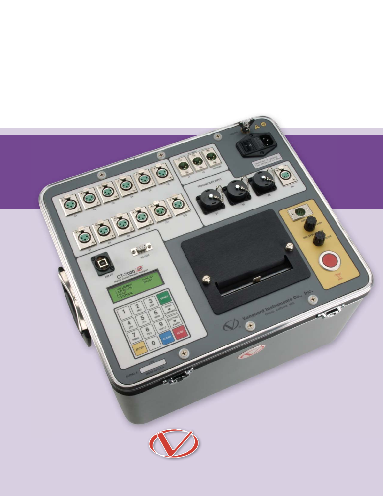
CT-7000 S2
digital circuit breaker analyzer
Vanguard Instruments Company, Inc.
www.vanguard-instruments.com
Page 2

CT-7000 S2
digital circuit breaker analyzer
The CT-7000 S2 is Vanguard’s third generation, stand-alone, microprocessor-driven
EHV circuit-breaker analyzer. This inexpensive and easy to use analyzer is available
in models with either 3 (CT-7000-3 S2), 6 (CT-7000-6 S2), or 12 (CT-7000-12 S2) drycontact inputs. The CT-7000 S2 can fully analyze a circuit-breaker’s performance by
testing the contact time, stroke, velocity, over-travel, and contact wipe. Contact motion
analysis can be performed for all circuit breaker operations (Open, Close, Open – Close,
Close – Open, and Open – Close – Open). The CT-7000 S2’s timing window is selectable
between 1-second, 10-second, or 20-second periods. The 10-second and 20-second
timing windows are ideal for timing long duration events such as circuit-switcher contact testing.
1
Contact Timing Inputs
The CT-7000 S2 is available in models with either 3
(CT-7000-3 S2), 6 (CT-7000-6 S2), or 12 (CT-7000-12
S2) dry-contact inputs. Each contact input channel can
detect main contact and insertion-resistor contact times
in milli-seconds and cycles.
2
Breaker Stroke and Velocity
Three digital travel transducer channels are available
on the CT-7000 S2 for measuring circuit-breaker velocity, stroke, over-travel, and bounce-back. Unlike other
transducer types, the digital transducer requires neither
calibration nor setup. A breaker’s contact-velocity is calculated based on the contact’s travel distance over a period of time. A special feature is also available to “slowclose” test a breaker and obtain a test result report.
3
Resistor Type Transducer
Input
One optional resistor type input channel is also
available on the CT-7000 S2. This input channel
allows the unit to measure circuit-breaker motion by directly interfacing with resistive type
transducers. The transducer resistance ranges
from 200 ohms to 10K Ohms.
4
Voltage Monitoring
Inputs
One analog voltage input channel, designated as
V1, is dedicated to monitoring a circuit-breaker’s
DC power supply or coil voltage (0 – 255 volts,
DC or peak AC). A second voltage input channel,
designated as V2, is dedicated to detecting the
voltage on/off status (presence or absence) of
an A/B switch.
5
Breaker Initiate Features
A built-in solid-state initiate device is used to
operate a breaker from the CT-7000 S2. The
operational modes include Open, Close, Open–
Close, Close–Open, and Open–Close–Open.
Multiple operations, such as Open–Close and
Open–Close–Open, can be initiated by using
programmable delay time or by sensing a breaker’s contact condition.
A built-in Hall-effect current sensor records
the Trip/Close current level and duration. The
breaker's operate-coil current waveform duration (effectively, a performance “fi ngerprint” or
“current profi le”) can be used as a diagnostic
tool for analyzing a breaker's performance.
6
Built-in Thermal Printer
The CT-7000 S2’s built-in 4.5-inch wide thermal
printer can print the breaker contact analysis results in both tabular and graphic formats.
ordering information
Part number CT-7000-3 S2 CT-7000 S2 with 3 contact channels, cables, and PC software
Part number CT-7000-6 S2 CT-7000 S2 with 6 contact channels, cables, and PC software
Part number CT-7000-12 S2 CT-7000 S2 with 12 contact channels, cables, and PC software
Part number CT-7000-CASE CT-7000 S2 shipping case
Part number Paper-TP4 Thermal printer paper
2
Page 3
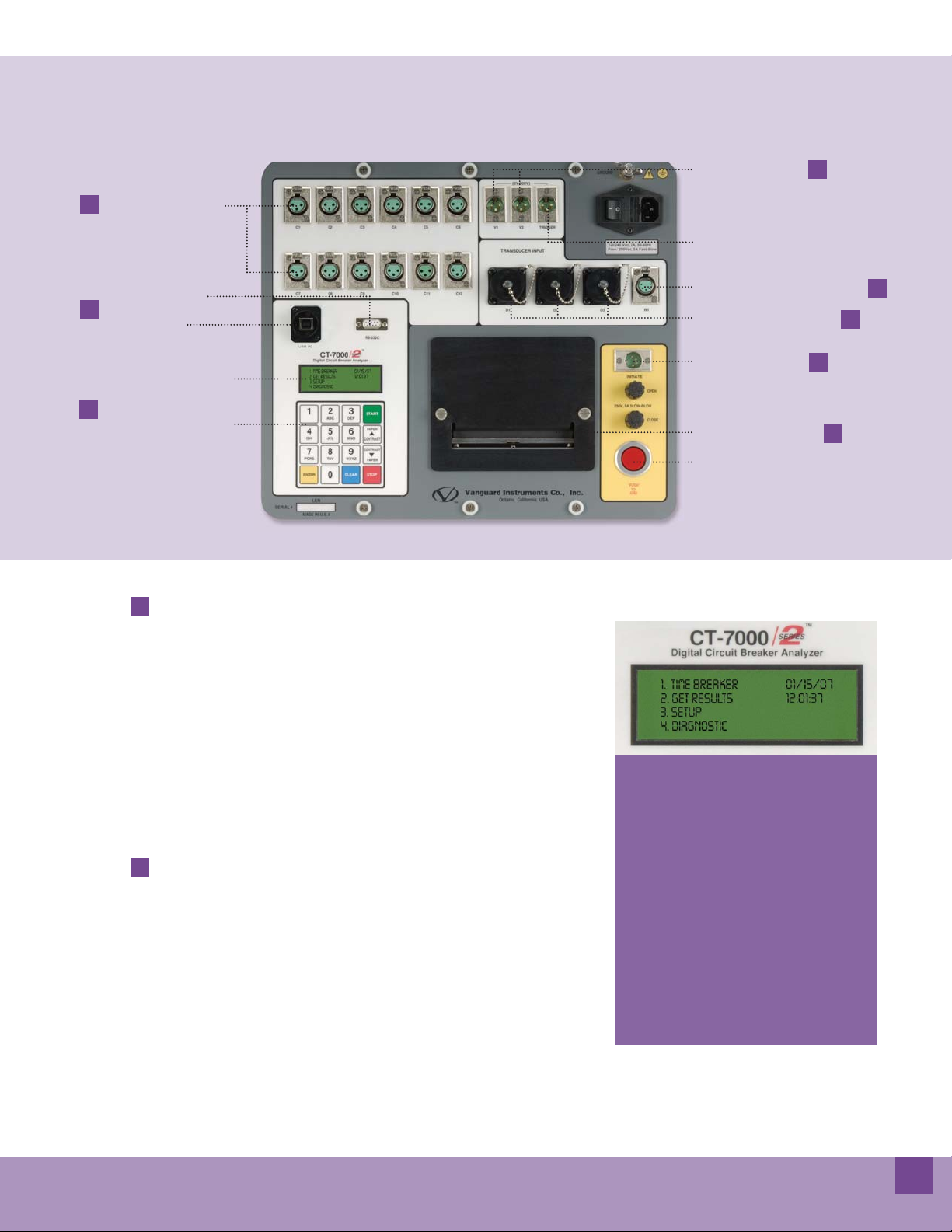
CT-7000 S2 Controls & Indicators
1
Contact Timing Channels
RS-232C PC Interface
7
USB PC Interface
Back-lit LCD Screen
(20 characters by 4 lines)
8
Rugged 16-key membrane
7
keypad
Voltage Input Channels
Trigger Input Connector
Resistor Type Transducer Connector
Digital Transducer Connectors
Breaker Initiate Output
4.5" Wide Thermal Printer
Breaker Initiate Arm Switch
4
2
5
6
3
Computer Interface
The CT-7000 S2 can be computer-controlled via
its RS232C or USB interface. Windows® based
BreakerAnalysis software is provided with each
unit. Using this software, circuit-breakers can
be timed from the PC. Test records can be retrieved from the CT-7000 S2 and then stored on
the PC for future analysis and report generation.
Circuit-breaker test plans can also be created on
the PC and transferred to the CT-7000 S2. Additionally, test records can be exported in Excel,
PDF, and XML formats for further analysis.
8
User Interface
The CT-7000 S2 features a back-lit LCD screen
(20 characters by 4 lines) that is viewable in
both bright sunlight and low-light levels. A rugged, 16-key, membrane keypad is used to control
the unit.
Internal Test Record and
Test Plan Storage
Up to 150 test records can be stored in Flash EEPROM. Test records can be retrieved and printed
on the built-in thermal printer, or they can be
transferred to a PC via the unit’s RS232C or USB
interface.
Up to 99 circuit breaker test plans can be stored
in Flash EEPROM. Test plans are comprised of
all circuit-breaker performance specifi cations
(stroke, velocity, and contact time). A test plan
can be used to immediately test a circuit-breaker. A pass/fail report is then generated by comparing actual performance with the specifi cations in the stored test plan. Test plans can also
be generated on a PC and transferred to the CT7000 S2 via the unit’s RS232C or USB interface.
Diagnostic Capabilities
The CT-7000 S2 can perform diagnostics on its
internal electronics. Diagnostics can also be performed to verify contact cable connections and
to test the travel transducer’s electronics.
outstanding features
• Prints breaker analysis results in both tabular
and graphic formats
• Built-in 4.5" wide thermal printer
• Initiate breaker operation
• Digital travel transducer requires no setup or
calibration
• Detects main contact and insertion contact on
the same input channel
• Stores up to 150 test records and 99 test plans
• RS-232C and USB computer interfaces
• Supports resistor type transducer
3
Page 4
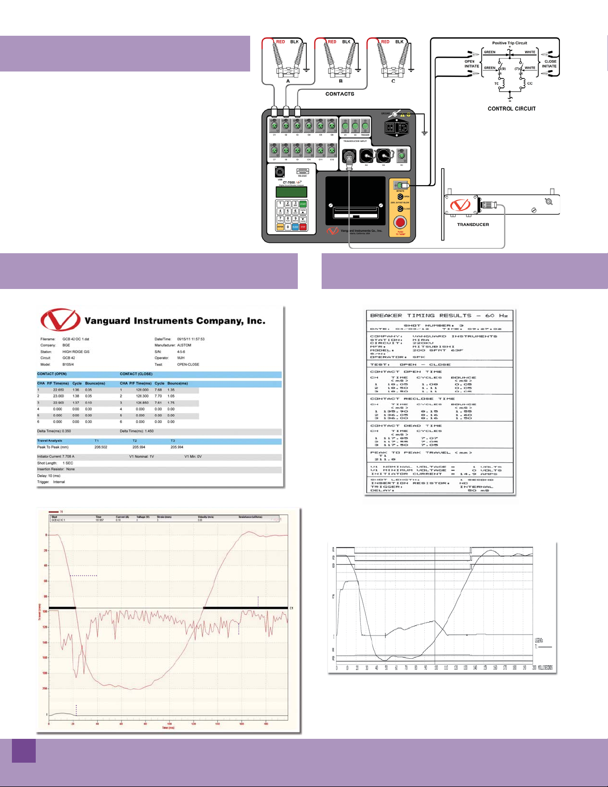
CT-7000 S2 connections
CT-7000 S2 desktop printer output
Desktop printout of tabulated test results
Desktop printout of graphic test results
CT-7000 S2 thermal printer output
Thermal printout of tabulated test results
Thermal printout of graphic test results
travel transducer trace
contact 1 trace
velocity curve
coil current trace
4
Page 5
Computer control and analysis with included VCBA S2 Software
The CT-7000 S2 comes with the Vanguard
Circuit Breaker Analysis Series 2 (VCBA S2) PC
software. The VCBA S2 software can be used
to retrieve timing records from the CT-7000 S2,
analyze retrieved records, view test results in
graphic format, generate timing reports, create
breaker test plans, transfer breaker test plans
to the CT-7000 S2, and control the CT-7000
S2 from the PC to perform timing tests. The
software can also be used to print test results
to a desktop printer.
CT-7000 S2 specifi cations
type portable digital circuit-breaker analyzer
physical specifi cations 16”W X 11”H x 14”D (40.6 cm x 29.9 cm x 35.6 cm); Weight: less than 25 lbs (11.3 kg)
input power 100 ¬ 240 Vac, 50/60 Hz
dry-contact inputs 3, 6, or 12 dry-input channels (depending on model). Each channel detects main and insertion resistor contacts
timing windows 1 second, 10 seconds, or 20 seconds
timing resolutions ±50 micro-seconds @ 1 sec. duration, ±500 micro-seconds @ 10 sec. duration, ±1.0 milli-seconds @ 20 sec. duration
timing accuracy 0.05% of reading ±0.05 ms @ 1 second duration
dry-contact channel protection all contact inputs are grounded until test; input channels are protected against static discharge
dry-contact detection range closed: less than 20 ohms; open: greater than 5,000 ohms
resistor detection range 50 ¬ 5,000 ohms
ct current sensor one, non-contact, 0 ¬ 100 amperes
trigger input voltage open/close: 30 ¬ 300 V, DC or peak AC
voltage sensing input range V1: analog input; 0 ¬ 255 V DC or peak AC; sensitivity ±1 V
V2: voltage presence/absence detector input; 30 ¬ 300 V DC or peak AC
breaker operations Initiate Open, Close, Open-Close, Close-Open, Open-Close-Open
breaker initiate capacity 30A, 250 Vac/dc max
initiate current reading range one, non-contact, Hall-effect sensor, 0 ¬ 20 amp range, dc to 5 Khz
digital travel transducer inputs 3 digital travel transducer channels; linear range: 0.0 ¬ 60.0 in (±0.01 in)
rotary range: 0 ¬ 360 degrees (±0.36 degrees)
optional resistor type
transducer input
contact travel point difference measures “slow-close” contact-point distances; results can be printed
internal test record storage stores up to 150 test records and 99 test plans
computer interfaces one RS-232C port, one USB port
pc software Windows® based Breaker Analysis software included with purchase price
environment Operating: -10°C to +50°C (+15°F to +122°F); Storage: -30°C to +70°C (-22°F to +158°F)
humidity 90% RH @ 40°C (104°F) non-condensing
altitude 2,000 m (6,562 ft) to full safety specifi cations
options transportation case (available for the CT-7500 S2 and travel transducers)
warranty one year on parts and labor
NOTE : the above specifi cations are valid at nominal voltage and ambient temperature of +25°C (+77°F). Specifi cations are subject to change without notice.
one channel, resistance range: 200 ohms ¬ 10 K ohms
display back-lit LCD screen (20 characters by 4 lines); viewable in bright sunlight and low light
printer built-in 4K” wide thermal printer that can print both graphic contact travel waveforms and tabulated test results
safety designed to meet UL 6101A-1 and CAN/CSA C22.2 No 1010.1-92 standards
cables furnished with full set of test leads (including 20-foot contact leads and 30-foot contact lead extensions)
5
Page 6

VCBA S2
Vanguard circuit breaker analyzer software
The Vanguard Circuit Breaker Analyzer Series 2 (VCBA S2) Windows®-based software is included with all compatible Vanguard
Circuit Breaker Analyzers (CT-6500 S2, CT-7000 S2, CT-7500 S2, CT-8000, DigiTMR S2, DigiTMR S2 PC) at no additional cost.
This robust application can be used to control the circuit breaker analyzer from a PC to perform CB timing tests. It can also be
used to retrieve test records from the circuit breaker analyzer, analyze timing records, and view test results in tabulated and
graphical format. Circuit breaker test plans can also be created and transferred to the circuit breaker analyzer.
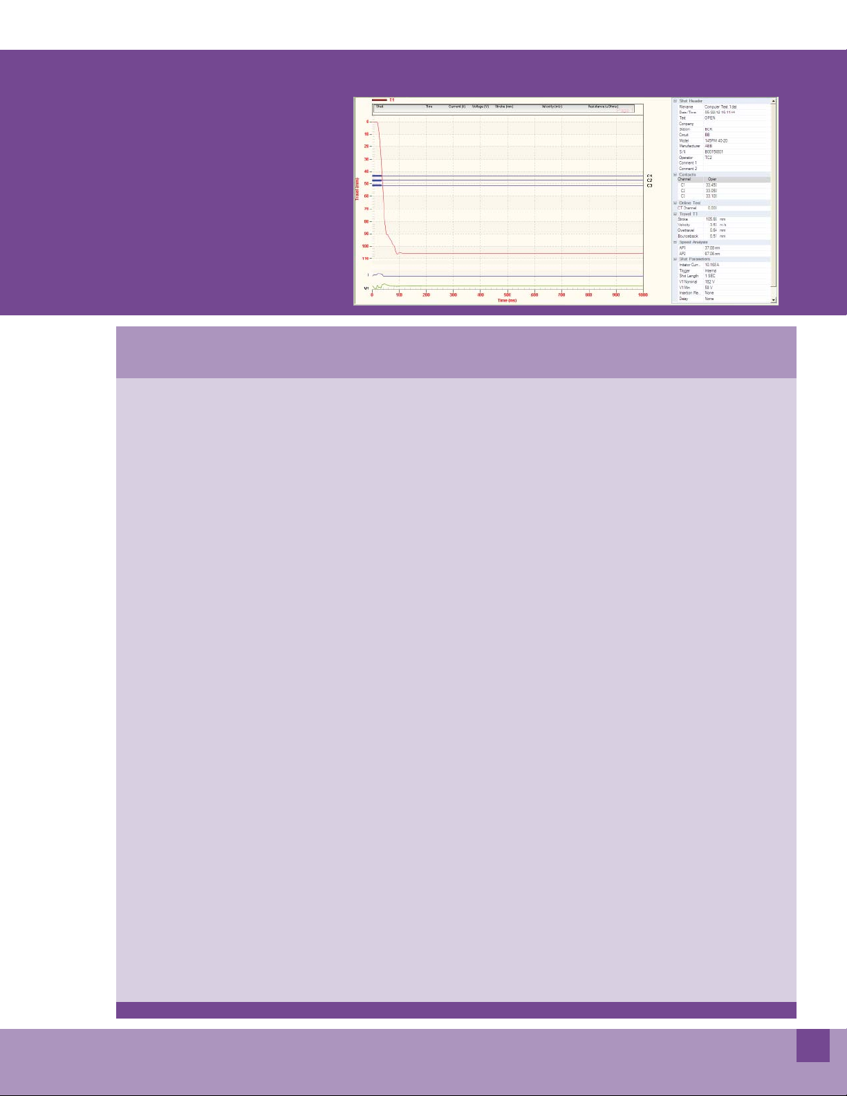
Retrieving and Analyzing Test Records
The VCBA S2 software can be used to quickly retrieve test records from a compatible Vanguard circuit breaker analyzer. Test
results can be viewed in tabular and graphical format and can be saved on the PC hard drive. Test record header information,
such as the company name, station, circuit, operator name, manufacturer, model, and serial number can also be edited.
Sample Test Results (OPEN Test)
Getting a Closer View with Graph Expansions
The VCBA S2 software can be used to expand a portion of the graphical test results for more accurate analysis.
Expansion Area
Velocity Trace
Graphical Test Results Graphical Test Results Expansion (from 0 to 200ms)
6
Page 7
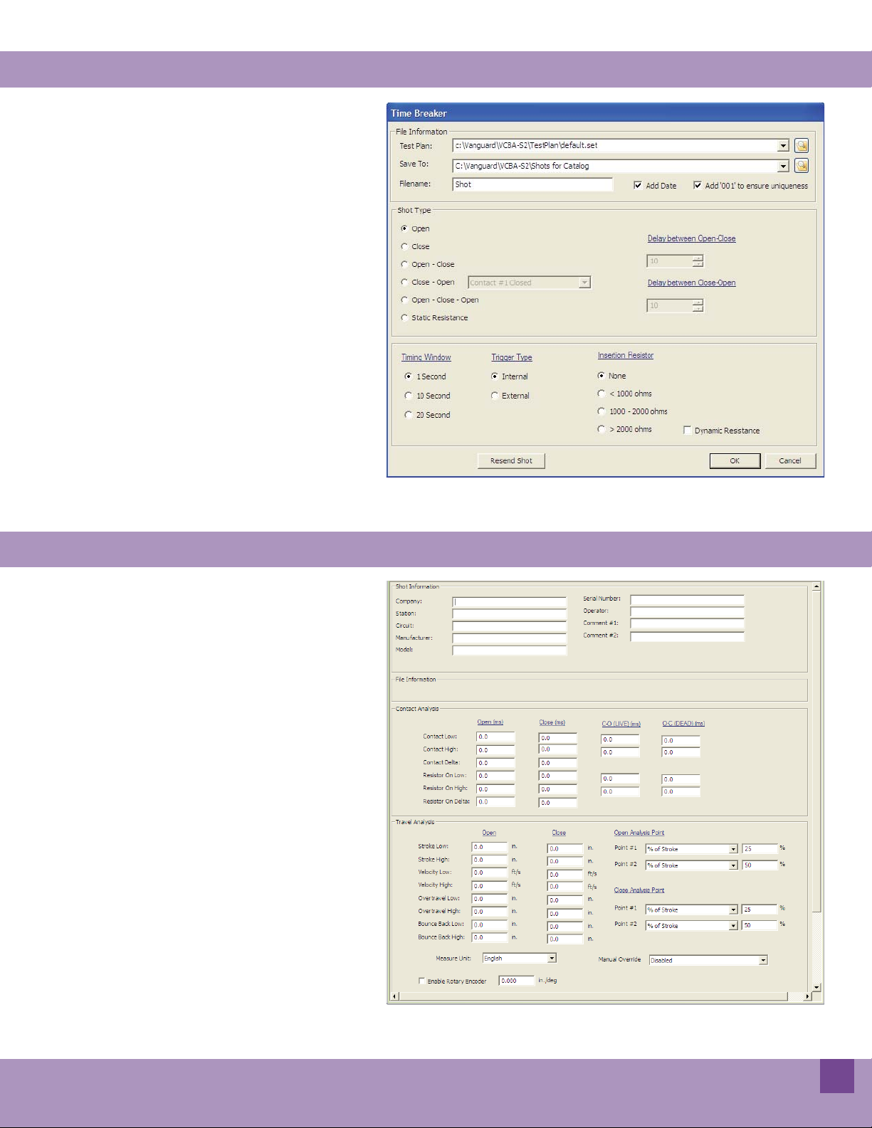
Timing a Circuit Breaker with the VCBA S2 Software
The VCBA-S2 software can be used to control a CB analyzer and run circuit breaker
timing tests. The following tests are supported: OPEN, CLOSE, OPEN-CLOSE,
CLOSE-OPEN, OPEN-CLOSE-OPEN, and
STATIC RESISTANCE. Also, a test plan for a
specifi c breaker can be used with the test.
If a test plan is used, the Pass/Fail indicator
will be displayed based on the settings in
the test plan.
Breaker Testing Parameters
Creating Test Plans for Faster Testing
A circuit breaker test plan is comprised of all
circuit-breaker performance specifi cations
(stroke, velocity, and contact time). A test
plan can be used to test a circuit breaker.
When used with a test record, a Pass/Fail
report is generated by comparing the actual performance of the breaker with the
specifi cations in the stored test plan. Test
plans can be easily created with the VCBAS2 software and can be stored on the hard
drive or transferred to a CB analyzer.
Creating a Test Plan
7
Page 8

Instruments designed and developed
by the hearts and minds of utility
electricians around the world
Vanguard Instruments Company, (VIC), was founded in 1991.
Currently, our 28,000 square-foot facility houses Administration,
Design & Engineering, and Manufacturing operations. From its
inception, VIC’s vision was, and is to develop and manufacture
innovative test equipment for use in testing substation EHV circuit
breakers and other electrical apparatus.
The fi rst VIC product was a computerized circuitbreaker analyzer,
which was a resounding success. It became the forerunner of an entire
series of circuitbreaker test equipment. Since its beginning, VIC’s
product line has expanded to include microcomputer-based, precision
micro-ohmmeters, single and three phase transformer winding turnsratio testers, transformer winding-resistance meters, mega-ohm
resistance meters, and a variety of other electrical utility maintenance
support products.
VIC’s performance-oriented products are well suited for the utility
industry. They are rugged, reliable, accurate, user friendly, and
most are computer controlled. Computer control, with innovative
programming, provides many automated testing functions. VIC’s
instruments eliminate tedious and time-consuming operations, while
providing fast, complex, test-result calculations. Errors are reduced
and the need to memorize long sequences of procedural steps is
eliminated. Every VIC instrument is competitively priced and is
covered by a liberal warranty.
Vanguard Instruments Company, Inc.
1520 S. Hellman Avenue • Ontario, California 91761, USA
Phone 909-923-9390 • Fax 909-923-9391
www.vanguard-instruments.com
August, 2012
 Loading...