

Page 1
Split Mount
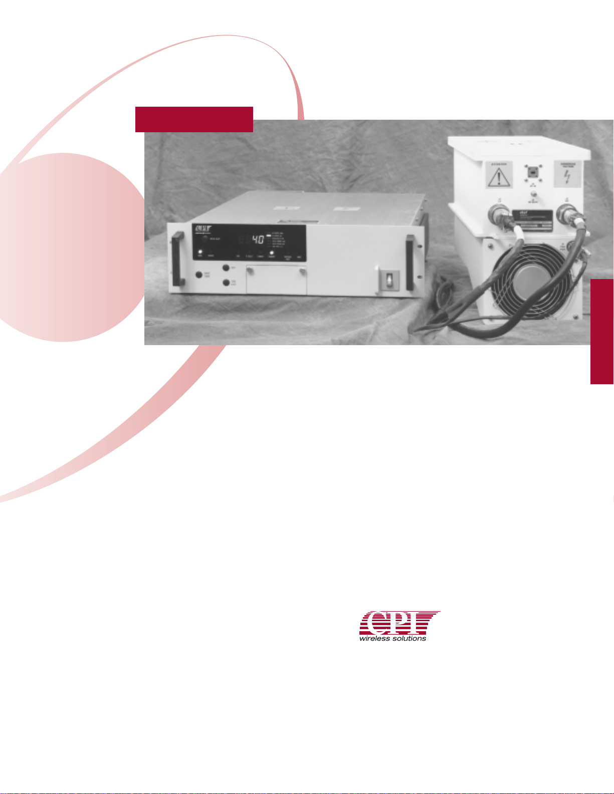
The split mount configuration provides for direct
feed mounting to minimize waveguide RF losses.
The power supply maintains the convenience of
a rack mounted unit with built-in monitors and
controls located up to 12 meters away.
Versatile
Ultra wide-band, automatic fault recycle, userfriendly microprocessor-controlled logic with
integrated RS-422/485 computer interface.
IEEE interface and other options available.
Easy to Maintain
Automatic sequencing of voltages and filament
time delay. The power supply HV outputs to the
appropriate TWT label voltages are automatically
set with an integrated, individualized TWT
personality interface module.
30 Millimeter TWT Amplifier
VSTAR®30 Millimeter TWT Amplifier
for Test and Measurement Applications
VZK-6901J1
40 Watt split mount
millimeter wave TWT
power amplifier —
environmentally
sealed compact
design for indoor or
outdoor operation.
K-Band
K-Band
Global Applications
Meets International Safety Standard EN-61010,
and Electromagnetic Compatibility 89/336/EEC
to satisfy worldwide requirements. Universal input
voltage range.
Worldwide Support
Backed by over two decades of satellite
communications experience, and CPI’s worldwide
24-hour customer support network that includes
9 regional factory Service Centers.
Communications & Power Industries Canada, Inc.
45 River Drive / Georgetown, Ontario / Canada L7G 2J4
Hot Line Telephone: 1-800-267-JETSAT
TEL: 905-877-0161 / FAX: 905-877-5327
E-MAIL: marketing@cmp.cpii.com
WEB: www.cpii.com/cmp
INSTRUMENTATION
AMPLIFIERS
Page 2

SPECIFICATIONS, VZK-6901J1
Electrical
TWT Model Number VTK-6193D series
Frequency 18.0 to 26.5 GHz
Output Power
TWT 40W min.
Flange 39W min.
Bandwidth 8.5 GHz, instantaneous
Gain
at rated power 46 dB min.
Gain Control Range 20 dB min.
Gain Variation
at 6 dB backoff ±5 dB over 8.5 GHz, typ.
Gain Stability ±0.25 dB/24 hr. max.at
constant drive and temperature
(after 1 hour warmup period)
Input VSWR 1.7:1 typ.; 2.4:1 max.
1.35:1 typ.; 1.5:1 max.,
(with optional input isolator)
Output VSWR 2.0:1 typ.; 2.7:1 max.
Load VSWR 2.0:1 max.; no degradation, infinite
VSWR without damage
Phase Noise
1.0 to 350 MHz -120 dBc/Hz max.
Below 1.0 MHz -6 dB below IESS 308
(-21 dB typ.)
Spurious -50 dBc
Noise Power Out +23 dBm max. total
Primary Power 100 to 264 VAC,
47 to 63 Hz, single phase
Power Consumption 700 VA typ.; 1200 VA max.
Power Factor .95 min.
Environmental (Operating)
Ambient Temperature
RF unit -10 to +50°C
(+65 with solar loading)
PS unit -10 to +50°C
Relative Humidity
RF unit 100% condensing
PS unit 95% non-condensing
Altitude 10,000 ft. with standard
adiabatic derating of
2°C/1,000 ft. operating
Shock and Vibration As encountered in normal
transportation
Acoustic Noise Meets EN61010 requirements
Mechanical
Cooling Forced air
RF Connectors
Input and Output WR-42 waveguide flange
RF Output Monitor Type K female
Dimensions, (W x H x D)
RF unit 8.5 x 12.83 x 20 in.
(216 x 324 x 508 mm.)
PS unit 19 x 5.25 x 24 in.
(483 x 133 x 610 mm.)
Weight (Standard amplifier, no options)
RF unit 40 lbs. max. (18.2 kg.)
PS unit 50 lbs. max. (22.7 kg.)
HV Cables/LV Cables 2.5 meters - 0 cm./+30 cm.
K-Band
For more detailed information, please refer to the corresponding
CPI
Technical Description.
Note: Specifications may change without notice as a result of additional data or product refinement.
Please contact
CPI
before using this information for system design.
MKT 49, ISSUE 3 1/99 2500
OPTIONS:
• Input Isolator
• IEEE-488 Interface
• RS-232 Interface
• Interconnect cable –
to 12 meters
INSTRUMENTATION
AMPLIFIERS
 Loading...