

Page 1
CMC 256plus
CMC 256plus: 6 Phase Current + 4 Phase Voltage Test Set and Universal Calibrator
The CMC 256plus is the first choice for applications requiring very high accuracy. This unit is
not only an excellent test set for protection devices of all kinds but also a universal calibration tool. Its high precision allows the calibration of a wide range of measuring devices,
including: electricity meters of class 0.2, measuring transducers, power quality measurement
devices and phasor measurement units (PMU). Its unique accuracy and flexibility make the
CMC 256plus ideal for protection and measurement equipment manufacturers for research
and development, production and type testing. The CMC 256plus can either be operated by
the Test Universe software running on a PC or by the front panel control device CMControl.
Technical Data
Current generators
Setting range 6-phase AC (L-N)
Power 6-phase AC (L-N)
2
Accuracy
Distortion (THD+N)
Ranges 1.25 A / 12.5 A (Group A, B) or
Resolution (for respective range)
Max. compliance voltage (L-N)/(L-L)
Connection 4 mm (0.16 in) banana sockets / combination
1
All data specified are guaranteed, except where indicated otherwise.
OMICRON guarantees the specified data for one year after factory calibration,
within 23 °C ±5 °C (73 °F ±10 °F) in the frequency range from 10 to 100 Hz and
after a warm-up phase > 25 minutes
2
Rload: 0 ... 0.5 W
3
rd. = reading, rg. = range
4
THD+N: Values at 50/60 Hz, > 1 A / 20 V with 20 kHz bandwidth
5
Rload: > 250 W
6
Amplitude derating at > 1000 Hz
7
Data are valid from 0.1 to 12.5 A (current amplifier A or B) and 50 to 300 V
(voltage amplifier) at 50/60 Hz
Permissible load for current outputs:
Range 1.25 A: 0 to 1 W and 1 VA max., cos ϕ = 0.5 to 1
Range 12.5 A: 0 to 0.5 W and 6 VA max., cos ϕ = 0.5 to 1
Permissible load for voltage outputs:
10 VA max. at 50 to 300 V, cos ϕ = 0.5 to 1
1
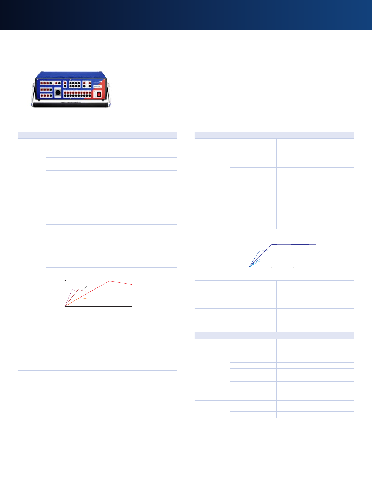
6 x 0 ... 12.5 A
3-phase AC (L-N)
1-phase AC (3L-N)
DC (3L-N)
3 x 0 ... 25 A (Group A II B)
1 x 0 ... 75 A (Group A II B), 2 x 0 ... 37.5 A
1 x 0 ... ±35 A (Group A II B), 2 x 0 ... ±17.5 A
6 x 80 VA typ. at 8.5 A, 6 x 70 VA guar. at 7.5 A
3-phase AC (L-N) 3 x 160 VA typ. at 17 A (Group A II B)
3 x 140 VA guar. at 15 A (Group A II B)
1-phase AC (3L-N) 1 x 480 VA typ. at 51 A (Group A II B),
2 x 240 VA at 25.5 A
1 x 420 VA guar. at 45 A (Group A II B),
2 x 210 VA at 22.5 A
1-phase AC (L-L) 1 x 320 VA typ. at 8.5 A (Group A II B),
2 x 160 VA at 8.5 A
1 x 280 VA guar. at 15 A (Group A II B),
2 x 140 VA at 7.5 A
1-phase AC (L-L-L-L) 1 x 320 VA typ. at 8.5 A
(40 VRMS, Group A and B in series)
1 x 280 VA guar. at 7.5 A
(40 VRMS, Group A and B in series)
DC (3L-N) 1 x 480 W typ. at ±35 A (Group A II B),
2 x 240 W at ±17.5 A
1 x 470 W guar. at ±35 A (Group A II B),
2 x 235 W at ±17.5 A
Group A
and B in
series
1-phase
AC (L-L)
3-phase AC (L-N)
Output current / A
1-phase AC (L-N)
500
400
300
200
100
0
0 10 25 50 75
Output power (typ.) / VA
error < 0.015 % rd.3 + 0.005 % rg.3 typ.
at 0 ... 12.5 A
error < 0.04 % rd. + 0.01 % rg. guar.
4
at 0 ... 12.5 A
< 0.025 % typ., < 0.07 % guar.
2.5 A / 25 A (Group A II B)
50 µA / 100 µA / 500 µA / 1 mA
15 Vpk / 60 Vpk
socket (Group A only)
Voltage generators
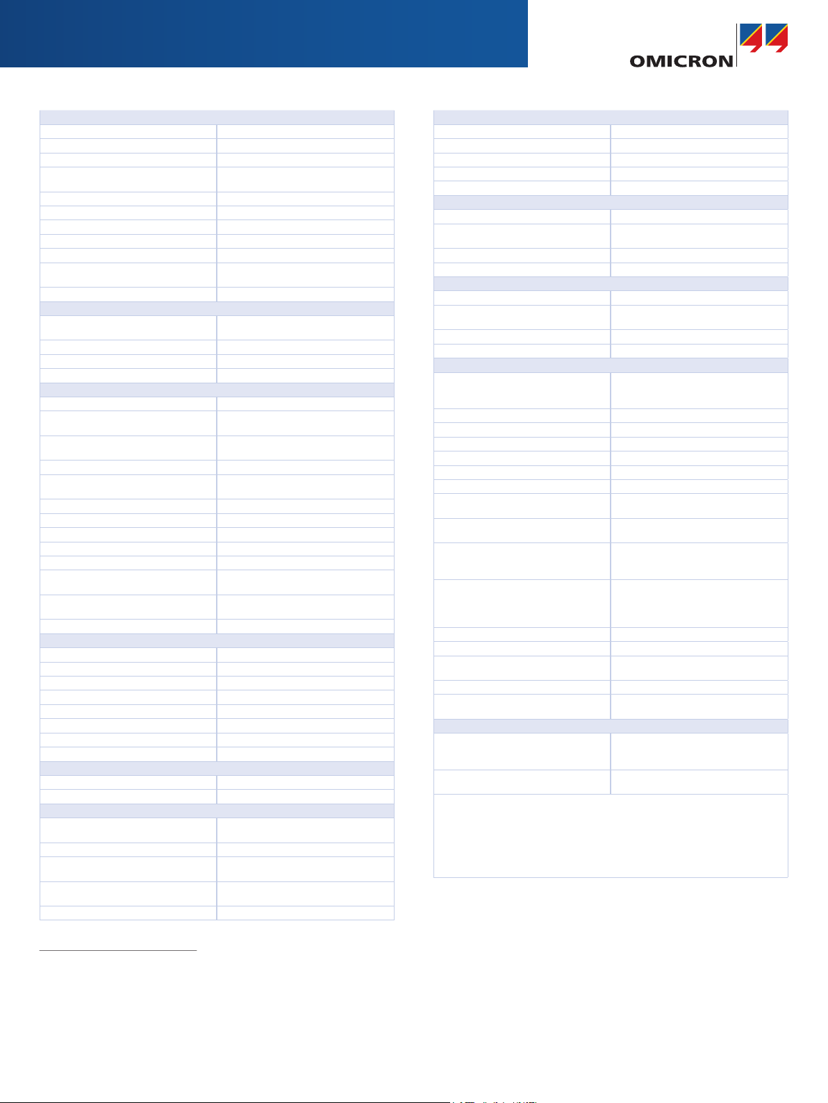
Setting range 4-phase AC (L-N) 4 x 0 ... 300 V (VL4(t) automatically
3-phase AC (L-N) 3 x 0 ... 300 V
1-phase AC (L-L) 1 x 0 ... 600 V
DC (L-N) 4 x 0 ... ±300 V
Power 3-phase AC (L-N) 3 x 100 VA typ. at 100 ... 300 V
4-phase AC (L-N) 4 x 75 VA typ. at 100 ... 300 V
1-phase AC (L-N) 1 x 200 VA typ. at 100 ... 300 V
1-phase AC (L-L) 1 x 275 VA typ. at 200 ... 600 V
DC (L-N) 1 x 420 W typ. at ±300 V
300
250
200
150
100
50
4-phase AC (L-N)
0
0 100 200 300 400 500 600
Output power (typ.) / VA
5
Accuracy
Distortion (THD+N)
4
Ranges 150 V / 300 V
Resolution 5 mV / 10 mV in range 150 V / 300 V
Connection 4 mm (0.16 in) banana sockets /
Generators, general
Frequency range sine signals 10 ... 1000 Hz
range harmonics /
interharmonics
6
range transient signals
accuracy / drift ±0.5 ppm / ±1 ppm
resolution < 5 µHz
Phase angle range -360° ... +360°
resolution 0.001°
error at 50 / 60 Hz < 0.005° typ., < 0.02° guar.
Bandwidth (-3 dB) 3.1 kHz
Simulated power
accuracy
7
S, P (calibration
of energy meters)
temperature drift < 0.001 % / °C typ., < 0.05 % / °C guar.
calculated: VL4 = (VL1+VL2+VL3)*c
or freely programmable)
3 x 85 VA guar. at 85 ... 300 V
4 x 50 VA guar. at 85 ... 300 V
1 x 150 VA guar. at 75 ... 300 V
1 x 250 VA guar. at 200 ... 600 V
1 x 360 W guar. at ±300 V
1-phase AC (L-L)
1-phase AC (L-N)
3-phase AC (L-N)
Output voltage / V
error < 0.015 % rd.3 + 0.005 % rg.3
typ. at 0 ... 300 V
error < 0.04 % rd. + 0.01 % rg. guar.
at 0 ... 300 V
0.015 % typ., < 0.05 % guar.
combination socket (1,2,3,N)
10 ... 3000 Hz
6
DC ... 3.1 kHz
error < 0.05 % rd. typ., < 0.1 % rd.
guar.
Page 2
Low level outputs
Number of outputs
1
6 (12 with Option LLO-2)
Setting range 0 ... ±10 Vpk
Max. output current 1 mA
Accuracy error < 0.025 % typ., < 0.07 % guar.
at 1 ... 10 Vpk
Resolution 250 µV
Distortion (THD+N)
2
< 0.015 % typ., < 0.05 % guar.
Unconventional CT/VT simulation linear, Rogowski (transient and sinewave)
Overload indication yes
Isolation SELV
Usability completely independent from internal
amplifier outputs
Connection 16 pin combination socket (rear side)
Auxiliary DC supply
Voltage ranges 0 ... 264 VDC, 0.2 A / 0 ... 132 VDC,
0.4 A / 0 ... 66 VDC, 0.8 A
Power max. 50 W
Accuracy error < 2 % typ., < 5 % guar.
Connection 4 mm (0.16 in) banana sockets
Binary inputs
Number 10
Trigger criteria Toggling of potential-free contacts or DC
voltage compared to threshold voltage
Input characteristics 0 ... ±600 VDC threshold or
potential-free
Ranges 100 mV / 1 V / 10 V / 100 V / 600 V
Resolution of threshold ±2 mV, ±20 mV, ±200 mV, ±2 V,
±20 V in ranges
Sample rate 10 kHz (resolution 100 µs)
Time stamping accuracy ±0.00015 % of rd.
3
±70 µs
Max. measuring time infinite
Debounce / Deglitch time 0 ... 25 ms / 0 ... 25 ms
Counting function < 3 kHz at pulse width > 150 µs
Galvanic isolation 5 galvanically isolated groups
(2+2+2+2+2)
Max. input voltage CAT IV / 150 V, CAT III / 300V, CAT II /
600 V (850 Vpk)
Connection 4 mm (0.16 in) banana sockets
Counter inputs 100 kHz
Number 2
Max. counting frequency 100 kHz
Pulse width > 3 µs
Threshold voltage 6 V
Voltage hysteresis 2 V
Max. input voltage ±30 V
Isolation SELV
Connection 16 pin combination socket (rear side)
Trigger on overload
Supported generators Current generators
Timer accuracy error < 1 ms
Binary outputs, relays
Type potential-free relay contacts, software
controlled
Number 4
Break capacity AC Vmax: 300 VAC / Imax: 8 A /
Pmax: 2000 VA
Break capacity DC Vmax: 300 VDC / Imax: 8 A /
Pmax: 50 W
Connection 4 mm (0.16 in) banana sockets
Binary outputs, transistor
Type open collector transistor outputs
Number 4
Update rate 10 kHz
Imax 5 mA
Connection 16 pin combination socket (rear side)
DC voltage measuring input
Measuring range 0 ... ±10 V
Accuracy error < 0.003 % rg.
3
typ.,
< 0.02 % rg. guar.
Input impedance 1 MW
Connection 4 mm (0.16 in) banana sockets
DC current measuring input
Measuring range 0 ... ±1 mA, 0 ... ±20 mA
Accuracy error < 0.003 % rg.
3
typ.,
< 0.02 % rg. guar.
Input impedance 15 W
Connection 4 mm (0.16 in) banana socket
Analog AC+DC measuring inputs
4
Type AC + DC analog voltage inputs
(current measurement with external
current clamps or shunt resistors)
Number 10
Nominal input ranges (RMS values) 100 mV, 1 V, 10 V, 100 V, 600 V
Amplitude accuracy error < 0.06 % typ., < 0.15 % guar.
Bandwidth DC ... 10 kHz
Sampling frequency 28.44 kHz, 9.48 kHz, 3.16 kHz
Input impedance 500 kW // 50 pF
Transient input buffer at 28 kHz 3.5 s for 10 input channels / 35 s for 1
input channel
Transient input buffer at 3 kHz 31 s for 10 input channels / 5 min. for 1
input channel
Transient trigger threshold voltage, power quality trigger:
sag, swell, harmonic, frequency,
frequency change, notch
Measurement functions I (AC + DC), V (AC + DC), phase,
frequency, power, harmonics,
transient recording, event recording,
trend recording
Input overload indication yes
Input protection yes
Max. input voltage CAT IV / 150 V, CAT III / 300V, CAT II /
600 V (850 Vpk)
Galvanic isolation 5 groups (2+2+2+2+2)
Connection 4 mm (0.16 in) banana sockets
(combined with binary inputs)
Time Synchronization
Timing accuracy
IRIG-B synchronization with CMIRIG-B
GPS synchronization with CMGPS
error < 1 µs typ., < 5 µs guar.
error < 1 µs typ., < 5 µs guar.
To external voltage Reference signal on binary input 10:
10 ... 300 V / 40 ... 70 Hz
With the unique PermaSync functionality (supported by TU 2.30 or higher), analog
and Sampled Values outputs stay permanently in sync with the internal CMC time
reference. In combination with the optional CMIRIG-B interface box, PermaSync
additionally allows the continuous synchronization of the output quantities with
an external IRIG-B time protocol or an external PPS signal. With CMIRIG-B it is also
possible to transmit the internal PPS signal of the CMC to the device under test (e.g.
PMUs or IEDs stimulated with a synchronized Sampled Values data stream).
1
For directly testing relays with low level inputs by simulating signals from non
conventional CTs and VTs with low level interfaces and for controlling external
amplifier units
2
THD+N: Values at 50/60 Hz, 20 kHz measurement bandwidth, nominal value, and
nominal load
3
rd. = reading, rg. = range
4
Up to three inputs can be used for measuring RMS values, frequency, and phase
angle without the EnerLyzer software license. Full functionality requires EnerLyzer
software license
Page 3

Technical Data CMC 256plus (continued)
IEC 61850 GOOSE
1
Simulation Mapping of binary outputs to data attributes in
published GOOSE messages.
Number of virtual binary outputs: 360
Number of GOOSEs to be published: 128
Subscription Mapping of data attributes from subscribed GOOSE
messages to binary inputs.
Number of virtual binary inputs: 360
Number of GOOSEs to be subscribed: 128
Performance Type 1A; Class P2/3 (IEC 61850-5).
Processing time (application to network or vice versa):
< 1 ms
VLAN support Selectable priority and VLAN-ID
IEC 61850 Sampled Values (Publishing)
1
Specification According to the “Implementation Guideline for
Digital Interface to Instrument Transformers Using
IEC 61850-9-2“ of the UCA International Users Group
Sampling Rate 80 samples per cycle for nominal frequencies of 50
Hz and 60 Hz; synchronized with CMIRIG-B.
Synchronization Synchronization attribute (smpSynch) is set when
the CMC is in synchronized operation mode utilizing
CMIRIG-B.
Sample count (smpCnt) zero is aligned with top of
the second (IRIG-B and PPS)
Accuracy data see above
VLAN support Selectable priority and VLAN-ID
Max. number of SV streams 2 (with option LLO-2: 3 SV streams)
Power supply
Nominal input voltage
2
100 – 240 VAC, 1-phase
Permissible input voltage 85 ... 264 VAC
Nominal frequency 50/60 Hz
Permissible frequency range 45 ... 65 Hz
Power consumption 1.4 kVA at 115 V
/ 2.3 kVA at 230 V
Rated current 12 A at 115 V / 10 A at 230 V
Connection Standard AC socket (IEC 60320)
Environmental conditions
Operation temperature
3
0 ... +50 °C (+32 ... +122 °F)
Storage temperature -25 ... +70 °C (-13 ... +158 °F)
Humidity range Relative humidity 5 ... 95 %, non-condensing
Vibration IEC 60068-2-6 (20 m/s
2
at 10 ... 150 Hz)
Shock IEC 60068-2-27 (15 g/11 ms half-sine)
Safety Standards, Electromagnetic Compatibility
EMC The product adheres to the electromagnetic compat-
ibility (EMC) Directive 2004/108/EC (CE conform).
Emission Europe EN 61326-1; EN 61000-6-4; EN 61000-3-2/3
International IEC 61326-1;IEC 61000-6-4; IEC 61000-3-2/3
USA FCC Subpart B of Part 15 Class A
Immunity Europe EN 61326-1; EN 61000-6-2;
EN 61000-4-2/3/4/5/6/11
International IEC 61326-1;IEC 61000-6-2;
IEC 61000-4-2/3/4/5/6/11
Safety The product adheres to the low voltage Directive
2006/95/EC (CE conform).
Europe EN 61010-1 Insulation of PC and SELV interfaces
complies with EN 60950-1
International IEC 61010-1
USA UL 61010-1
Canada CAN/CSA-C22.2 No 61010-1-04
1
Testing with GOOSE and Sampled Values functionality requires software licences for
the corresponding configuration modules
2
For line inputs below 115 VAC, it is not possible to drive all outputs (voltage
output, current output, Aux DC) simultaneously at full load. All other technical
specifications (e.g. the maximum output power of a single amplifier) are not
affected
3
For an operational temperature above +30 °C (+86 °F) a duty cycle of down to
50 % may apply
4
PoE = Power over Ethernet
5
CMC 256plus with PAR-1 option is connected to the USB port of the PC by means
of the parallelport cable and the CMUSB-P (USB to Parallel Port Converter).
CMC 256plus equipped with the PAR-1 option can not be extended with the LLO-2
option and does not support the CMIRIG-B accessory
Miscellaneous
Weight 15.9 kg (35 lbs)
Dimensions (W x H x D, without handle) 450 x 145 x 390 mm (17.7 x 5.7 x 15.4 in)
PC connection Two 10/100 Mbit/s PoE
4
Ethernet ports:
• 10/100 Mbit/s (10/100 Base-TX,
auto-sensing, auto-crossover, RJ45
connector for twisted pair cables)
• IEEE 802.3af compliant
• Port capability limited to one Class 1
(3.84 W) and one Class 2 (6.49 W)
powered device
If equipped with PAR-1 option: Parallel
port (IEEE 1284-C connector). Replaces
the standard Ethernet interfaces by a
parallel port if required by the used PC or
if the binary extension device CMB IO-7
should be used
5
Signal indication (LED) > 42 V for voltage outputs and AUX DC
Connection to ground (earth) 4 mm (0.16 in) banana socket (rear side)
Hardware diagnostics Self diagnostics upon each start-up
Galvanically separated groups The following groups are galvanically
separated from each other: mains, voltage amplifier output, current amplifier
group A/B, auxiliary DC supply, binary/
analog input
Protection All current and voltage outputs are fully
overload and short circuit proof and
protected against external high-voltage
transient signals and over temperature
Certifications
Developed and manufactured under an
ISO 9001 registered system
Ordering Information
CMC 256plus with Test Universe Software
VE002701 CMC 256plus Basic
VE002702 CMC 256plus Protection
VE002703 CMC 256plus Advanced Protection
VE002704 CMC 256plus Universal
VE002705 CMC 256plus Meter
VE002706 CMC 256plus Measurement
CMC 256plus with CMControl (without Test Universe Software)
VE002715 CMC 256plus with CMControl-6
The CMControl can also be ordered as add-on together with a
CMC 256plus with Test Universe software or as a later upgrade.
CMC 256plus Hardware Options
VEHO2703 Option LLO-2 if ordered with a new unit
VEHO2704 Option LLO-2 if ordered as an upgrade
VEHO2701 Option PAR-1 if ordered with a new unit
VEHO2702 Option PAR-1 if ordered as an upgrade
5
5
 Loading...