

Page 1
AMX Power Systems
8kVA to 30kVA
20-5,000 Hz
0-338VL-N
1Ø4
0-600V
2Ø4
3Ø4
0-338V
Standard Features:
• Master/Slave Operation of 2 to 5 AMX AC
Power Sources provides AC Power Levels to
from 8KVA up to 30KVA
• Advanced Linear Ampliers Provide Very Low
Voltage Distortion, No Switching Noise, Fast
Voltage and Current Slew Rates, Exceptionally
Low Output Impedance and High Peak
Current Capability
• 1, 2, or 3 Phase Output Form Selectable from
Front Panel or Bus Command
• 20 to 5,000 Hz. Operation – 5Hz to 50KHz small
signal bandwidth, 3dB at 10% of Full Voltage
• Precision Voltage Programming – 0.05% with
Continuous Self-Calibration (CSC) engaged
• True-RMS Metering of Volts, Amps, and Power
• GPIB (IEEE-488.2) or RS-232 Interface
• Waveform Library – Arbitrary Waveform
Generator
• 99 Programs with Associated Transients for
Static and Dynamic Test Applications
• UPC Studio Software Suite
Available Options:
• T-Versions Include Transformer Assembly for
Higher Voltage Ranges
• Fully Installed and Wired in Industrial Strength
Instrument Cabinet with Caster Base
• Programmable Output Impedance
• Harmonic Analysis and Waveform Synthesis
• UPC Test Manager Software Application
• IEC Test Sequence Available for IEC 61000-
4-11, -4-13, -4-14, -4-27, -4-28 and -4-34 AC
Immunity Testing
UPC Manager Software Suite
Master the Power of the Wave!
UPC Manager Software
gives you the tools necessary to quickly and easily operate your AC Power Source.
With our graphical interface
control all areas of your
AC Power Source testing
with simple presets, user
prompts, test sequences,
test plans and custom
reports..
L-L
/585V
L-N
L-L
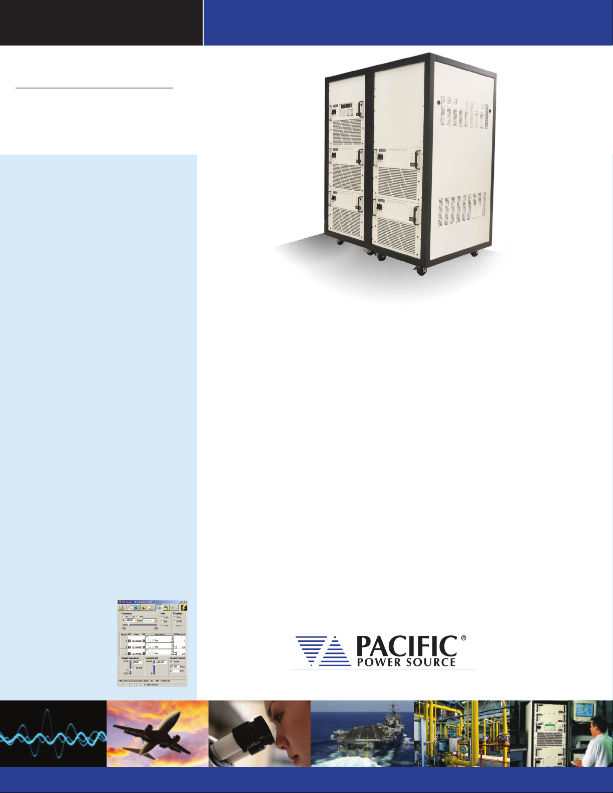
Parallel AMX AC Power Systems
Parallelable AMX Models
These special version AMX units are designed to easily parallel in a master slave
conguration to allow high power cabinet systems to be created ranging from 8kVA
to 30kVA. Either 4.5KVA or 6KVA AMX/AMXT units are used as building blocks for these
power racks.
The versatility of the Master/Slave Paralleling option provided by the
140/160/345/360AMX and 140/160/345/360AMXT AC Power Sources provide the
operator with a wide variety of options using a building block approach to higher
capacity linear AC Power Source systems. Each parallelable group of AC Power
Sources requires at least one ‘Master’ (/MST) unit with either UPC-12 or UPC-32
controller and one or more “Slave” (/SLV) units. Any /MST unit can be used as a /
SLV with another /MST unit by setting a rear panel mounted switch. This feature
provides great exibility for reconguring multiple units into a larger power system as demanded by changing application requirements.
As a member of Pacic's AMX-Series popular family of high performance Linear
AC Power Sources, these AMX systems oer the same absence of output switching
noise and very low voltage distortion, ease of installation, and high AC waveform
delity as found in Pacic's single chassis Linear AC Power Sources.
The Leader in AC Power Technology
An early pioneer in the development solid-state power conversion equipment, Pacic
Power Source continues to develop, manufacture, and market both linear and highperformance PWM AC Power Sources. Pacic Power Source’s reputation as a market
and technology leader is best demonstrated by its continuing investments in both
research and development and world-wide customer support. With corporate owned
oces in the United States, France, the United Kingdom, and China, local personalized
support is always available.
THE POWER OF EXPERTISE
FREQUENCY CONVERSION R & D MANUFACTURINGAEROSPACE MILITARY CUSTOM
Page 2
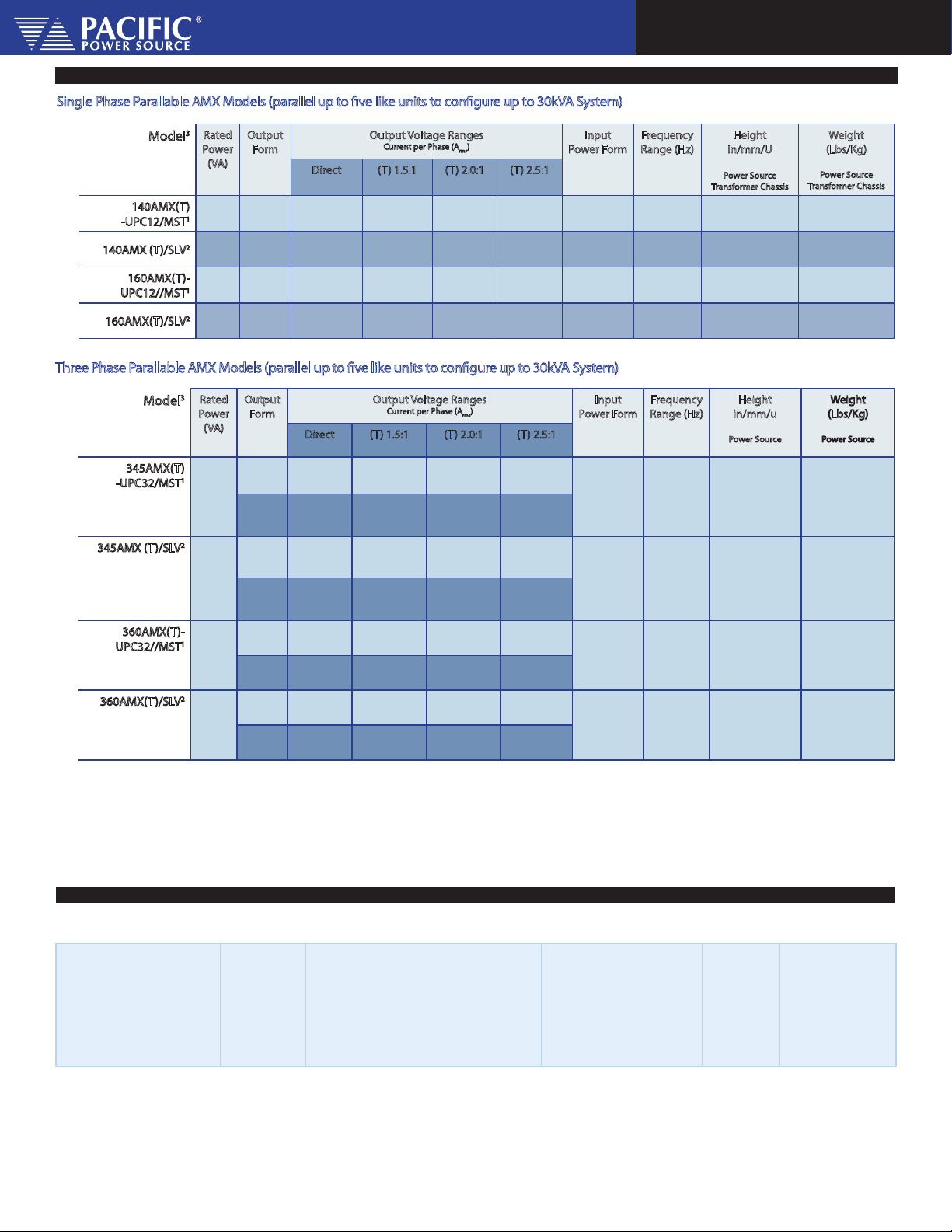
Output Ratings
Single Phase Parallable AMX Models (parallel up to ve like units to congure up to 30kVA System)
3
Rated
Model
140AMX(T)
-UPC12/MST
140AMX (T)/SLV
160AMX(T)-
UPC12//MST
160AMX(T)/SLV
1
2
1
2
Power
(VA)
4000
4000
6000
6000
Output
Form
1Ø/2Ø
1Ø/2Ø
1Ø/2Ø
1Ø/2Ø
Direct (T) 1.5:1 (T) 2.0:1 (T) 2.5:1
0-135/270
32/16
0-135/270
32/16
0-135/270
48/16
0-135/270
48/16
Three Phase Parallable AMX Models (parallel up to ve like units to congure up to 30kVA System)
3
Rated
Model
345AMX(T)
-UPC32/MST
345AMX (T)/SLV
1
2
Power
(VA)
4500
4500
5
5
Output
Form
1Ø/2Ø
3Ø
1Ø/2Ø
Direct (T) 1.5:1 (T) 2.0:1 (T) 2.5:1
0-135/270
36/12
0-135/234
12/ø
0-135/270
36/12
Output Voltage Ranges
Current per Phase (A
0-202/404
21.3/10.7
0-202/404
21.3/10.7
0-202/404
32/10.6
0-202/404
32/10.6
Output Voltage Ranges
Current per Phase (A
0-202/404
24/8
0-202/350
8/ø
0-202/404
24/8
rms
0-270/540
16/8
0-270/540
16/8
0-270/540
24/8
0-270/540
24/8
0-270/540
18/16
0-270/468
6/ø
0-270/540
18/16
)
0-338/600
12.8/6.4
0-338/600
12.8/6.4
0-338/600
19.2/6.4
0-202/404
19.2/6.4
)
rms
0-338/600
14.4-4.8
Input
Power Form
3Ø
47-63 Hz
3Ø
47-63 Hz
3Ø
47-63 Hz
3Ø
47-63 Hz
Input
Power Form
3Ø
47-63 Hz
0-338/585
4.8/ø
0-338/600
14.4/4.8
3Ø
47-63 Hz
AMX Power Systems
Frequency
Range (Hz)
20-5000 (PS): 14/356/8U
20-5000 (PS): 14/356/8U
20-5000 (PS): 14/356/8U
20-5000 (PS): 14/356/8U
Frequency
Range (Hz)
20-5000 (PS): 14/356/8U
20-5000 (PS): 14/356/8U
Height
in/mm/U
Power Source
Transformer Chassis
(T): 5.25/133/3U
(T): 5.25/133/3U
(T): 5.25/133/3U
(T): 5.25/133/3U
Height
in/mm/u
Power Source
(T): 5.25/133/3U
(T): 5.25/133/3U
Weight
(Lbs/Kg)
Power Source
Transformer Chassis
(PS):185/84.0
(T): 125/56.8
(PS):185/84.0
(T): 125/56.8
(PS): 195/88.6
(T): 125/56.8
(PS): 195/88.6
(T): 125/56.8
(Lbs/Kg)
Power Source
(PS):185/84.0
(T): 125/56.8
(PS):185/84.0
(T): 125/56.8
Weight
0-135/234
3Ø
12/ø
360AMX(T)-
UPC32//MST
6000
1
1Ø/2Ø
3Ø
0-135/270
48/16
0-135/234
6
16/ø
360AMX(T)/SLV
6000
1Ø/2Ø
0-135/270
6
2
48/16
0-135/234
3Ø
16/ø
NOTES:
1. Parallelable “Master’ (/MST) supplied with UPC-12/32 Controller. Power Source provided with Master/Slave mode select switch on rear panel
2. Dedicated “Slave” (/SLV) Power Source requires master unit of same model. No UPC required for Slave units.
3. Complete Model number for basic unit shown.
4. MST formerly referred to as M5283, SLV formerly referred to as M5283/M5304.
5. 3kVA in Form 2/ Split phase mode
6. 4kVA in Form 2/ Split phase mode
AMX Power Source Specications (PF = 1.0, V
Output Frequency
Full Power
20-5,000 Hz Direct Coupled
45-5,000 Hz Transformer Coupled
Line Regulation
0.1% max for a
±10% line
change
Improves to less than 0.03% with external sense and CSC enabled.
0-202/350
8/ø
0-202/404
32/10.6
0-202/350
10.7/ø
0-202/404
32/10.6
0-202/350
10.7/ø
> 25% F.S.)
out
0-270/468
6/ø
0-270/540
24/8
0-270/468
8/ø
0-270/540
24/8
0-270/468
8/ø
0-338/585
0-338/600
0-338/585
0-338/600
0-338/585
Load Regulation
Direct Coupled Ranges:
0.25% 20 to 2,000 Hz.
0.50% 2,000 to 5,000 Hz.
Transformer Coupled Ranges:
1:5:1 2%
2:0:1 4%
Improve to < 0.1% with external sense and CSC enabled.
2:5:1 5%
4.8/ø
19.2/6.4
6.4/ø
19.2/6.4
6.4/ø
3Ø
47-63 Hz
3Ø
47-63 Hz
Output Distortion
0.1% THD
AVG
0.25% THD
45 to 1,000 Hz
20 to 5,000 Hz
AVG
20-5000 (PS): 14/356/8U
(T): 5.25/133/3U
20-5000 ((PS): 14/356/8U
(T): 5.25/133/3U
Ripple and Noise
-72dB
(PS): 195/88.6
(T): 125/56.8
(PS): 195/88.6
(T): 125/56.8
Response Time
5 µsec typ. For
step load change.
Small signal
bandwidth = 5 Hz
to 40 KHz
© 2012 Pacic Power Source, Inc. Specications subject to change without notice.
DS#6AMXMSTSLV1112
Page 2 of 6
Page 3

AMX Power Systems
Input Power Requirements (47-63 Hz)
Refer to 140AMX/140AMXT, 160AMX/160AMXT,
345AMX/345AMXT or 360AMX/360AMXT Data sheets
for specic model Input Power requirements. Note MST
and SLV have same input requirements as respective
standard AMX models.
Power Factor Rating Curves per chasis
Thermal and Power Factor Rating Curves
Rated Continuous Load Current as a Function of Ambient
Temperature. Data is shown for combined system conguration.
THERMAL RATING -AC CURRENT RMS
Short tem overloads to 150% of rated current are permitted. Operating time
before thermal shutdown or circuit breaker trip varies from seconds to several
minutes depending upon line and temperature conditions.
Rated Power Factor and Output Voltage at Nominal Input Line. Data is shown for individual MST or SLV chassis. Multiply
Output Current by number of units to obtain total Output Current.
140AMX
345AMX
160AMX
360AMX
OUTPUT VOLTAGE – AC VOLTS RMS
Short tem overloads to 150% of rated current are permitted. Operating time before thermal shutdown or circuit breaker trip varies from
seconds to several minutes depending upon line and temperature conditions.
© 2012 Pacic Power Source, Inc. Specications subject to change without notice.
DS#6AMXMSTSLV1212
Page 3 of 6
Page 4

Typical System Conguration Examples
Single Phase Parallable AMX Models
Output Power
8kVA
(2 x 4kVA)
12kVA
(2 x 6kVA)
18kVA
(3 x 6kVA)
24kVA
(4 x 6kVA)
Three Phase Parallable AMX Models
Output Power
13.5kVA
(3 x 4.5kVA)
18kVA
(3x 6kVA)
24kVA
(4 x 6kVA)
30kVA
(5 x 6kVA)
Number of Master
Units
1 140AMXT-UPC12/MST 1 140AMXT/SLV
2 140AMXT-UPC12/MST 0 -
1 160AMXT-UPC12/MST 1 160AMXT/SLV 96A @ 125V
2 160AMXT-UPC12/MST 0 -
1 160AMX-UPC12/MST 2 160AMX/SLV 144A @ 125V
2 160AMX-UPC12/MST 1 160AMX/SLV
3 160AMX-UPC12/MST 0 -
1 160AMX-UPC12/MST 3 160AMX/SLV 192A @ 125V
2 160AMX-UPC12/MST 2 160AMX/SLV
3 160AMX-UPC12/MST 1 160AMX/SLV
4 160AMX-UPC12/MST 0 -
Number of Master
Units
1 345AMXT-UPC32/MST 2 345AMXT/SLV
2 345AMXT-UPC32/MST 1 345AMXT/SLV
3 345AMXT-UPC32/MST 0 -
1 360AMXT-UPC32/MST 2 360AMXT/SLV
2 360AMXT-UPC32/MST 1 360AMXT/SLV
3 360AMXT-UPC32/MST 0 -
1 360AMXT-UPC32/MST 3 360AMXT/SLV
2 360AMXT-UPC32/MST 2 360AMXT/SLV
3 360AMXT-UPC32/MST 1 360AMXT/SLV
4 360AMXT-UPC32/MST 0 -
1 360AMXT-UPC32/MST 4 360AMXT/SLV
2 360AMXT-UPC32/MST 3 360AMXT/SLV
3 360AMXT-UPC32/MST 2 360AMXT/SLV
4 360AMXT-UPC32/MST 1 360AMXT/SLV
5 360AMXT-UPC32/MST 0 -
Master Model Number Number of
Slave Units
Master Model Number Number of
Slave Units
AMX Power Systems
Slave Model Number Max. Current Number of Chassis Total Height
64A @ 125V
32A @ 250V
48A @ 250V
48A @ 250V
64A @ 250V
Slave Model Number Max. Current
Per Phase
36A @ 125V
18A @ 250V
48A @ 125V
24A @ 250V
64A @ 125V
32A @ 250V
80A @ 125V
40A @ 250V
2 PS + 2 XFMR 22U
2 PS + 2 XFMR 22U
3 PS 24U
4 PS 32U
Number of Chassis Total Height
3 PS + 3 XFMR 33U
3 PS + 3 XFMR 33U
4 PS + 4 XFMR 44U
4 PS + 4 XFMR 33U
Flexible Re-Conguration
Addition or deletion of power source chassis is easily performed by the user in eld. The standard AMX-Series features,
such as automatic output form selection, extensive output metering, etc. remain intact.
Note that only like models may be paralleled with each other. That is, only 345AMX chassis may be paralleled with other
345AMX chassis, 140AMX with 140 AMX, etc. All Master units are master/slave selectable from rear panel switch.
© 2012 Pacic Power Source, Inc. Specications subject to change without notice.
DS#6AMXMSTSLV1212
Page 4 of 6
Page 5

AMX Power Systems
Total Control, Metering, and Analysis of AC Power- Simple, Intuitive Operation
The UPC Controller is a highly versatile one, two, or three
phase oscillator/signal generator designed to control
any of Pacic Power’s AC Power Sources. Only the full
featured UPC-12 or UPC-32 Controller is oered for use
with the 3 single or three phase parallelable AMX models.
Using the front panel keyboard and display, all control-
ler models provide for selection of power source output
mode, coupling, voltage, and frequency. Selecting the
correct UPC controller for a given application varies with
your test requirement, desired features, and price.
Both the UPC-12 and UPC-32 Controllers are available
with either RS-232 or GPIB remote interface. Commands
are structured in accordance with SCPI (Standard Commands for Programmable Instruments).
Controller Models
Features UPC-12
Output Modes
Waveform Library
Transient Functions
Program Library
Programmable Current Limit
Programmable Current Protect
Programmable Phase Angle
CSC (Continuous Self-Calibration)
Remote Interface
Waveform Synthesis/Analysis
Prog. Output Impedance
DRM Link-Synchronization
Line Synchronization
Std
Opt
1Ø, & 2Ø
Sine +
15 Editable
YES, 99 Steps
99 Programs
YES YES
YES
YES, 0 to 359°
YES
GPIB
RS-232
OPTIONAL OPTIONAL
OPTIONAL
OPTIONAL
UPC-32
1Ø, 2Ø, & 3Ø
Sine +
15 Editable
YES, 99 Steps
99 Programs
YES
YES, 0 to 359°
YES
GPIB
RS-232
OPTIONALOPTIONAL
OPTIONAL
OPTIONAL
External Inputs/Outputs
Analog Auxilary Input
AM-Amplitude Modulation
Sync Outputs Zero Crossing
Transient Trigger
Transient Pedestal
Output Clock
Each phase is algebraically summed with UPC waveform
and amplied 25X to the direct coupled output.
±10Vpk (20Vpk-pk). One input per phase. ZIN = 600 Ω
±10 Vdc (20Vpk-pk) modulates the output voltage
±100%
One input per phase. Z
Positive Zero Crossing (0°) of Phase A analog output
Pulse at the start of a transient event.
TTL True when a transient is in progress
UPC-32, TTL level 1024 x output frequency
= 600 Ω
IN
Waveform Control
Waveform Synthesis
(/HAS Option)
Waveform Analysis
(/HAS Option)
Creates waveform by entering magnitude as %
of fundamental and specied phase angle for
2nd through the 51st harmonic
Reports waveform harmonic content and phase
angle relative to the fundamental for the 2nd
through the 51st harmonic as Total, Odd, and
Even harmonic distortion
4 x 16 Character LCD
Program Edit and Function Key
Output Control Specications
Voltage
Range
Resolution
Accuracy
Range (l-n)
Resolution
Accuracy
Range
Resolution
Accuracy
Range
Resolution
Accuracy
Frequency
Phase Angle
ØB and ØC relative to ØA
Current Limit
Output Metering
Voltmeter
True V
phase
Ammeter
True A
Apk each phase
Power Meter
True Watts and
Volt-Amps each
phase
Power Factor
Ratio : kW
Crest Factor
Ratio: Apk/A
Freq. Display
mtr
RMS
RMS
/kVA
each
and
mtr
RMS
Range
Resolution
Accuracy
Range
Resolution
Accuracy
Range
Resolution
Accuracy
Resolution
Accuracy
Resolution
Accuracy
Range
Resolution
Accuracy
Parameter Control
Ouput Control, Slew, and enable Keys
UPC-12
(1)
20-5,000Hz
0.5% of full scale (CSC Disabled)
±0. 05% referenced to Internal Meter (CSC Enabled)
±0. 5°
Function of the number of units in parallel.
UPC-12
4 Signicant Digits
±0.01% of full scale
0 - 150/375
0.1V/ 0.5V
0 - 359°
± 1°
0.05% F.S.
±1% F.S.
0-354 V
, 708V
L-N
0.1V front panel
50-500Hz, ± 0.25% of rdg.
± 0.1% F.S.
20-5,000 Hz, ± 0.5% F.S.
Function of the number of units in parallel.
0.01A front panel
±0.25% of rdg.
50-500Hz, ± 0.1% F.S.
20-5,000 Hz, ± 0.5% F.S.
Function of the number of units in parallel.
1.0 Watt or VA front panel
± 1% full range
Calculated and displayed to three
digits following the decimal point.
± 1 % full range
Calculated and displayed to three
digits following the decimal
± 1 % full range
20.00-5,000Hz
10.00-99.99 Hz, 0.01 Hz
100.0-999.9 Hz, 0.1 Hz
1,000-5,000 Hz, 1 Hz
± 0.01% full range
UPC-32
20-5,000Hz
UPC-32
L-L
© 2012 Pacic Power Source, Inc. Specications subject to change without notice.
DS#6AMXMSTSLV1212
Page 5 of 6
Page 6

AMX Power Systems
Temperature
Humidity
Cooling Per Unit
Altitude
Heat Dissipation Per Unit
Audible Noise
Agency Approvals
Hardware
Programmable Current Limit
Programmable Current Protect
General/Environmental
Operating: 0° to 55° C
Storage: -10 ° to 70° C
0 - 95%, Non-condensing
Front and side forced air intake (600 CFM) with rear exhaust.
Automatic Fan Speed Control for low acoustic noise and
extended fan life.
Operating: 6,500 Ft (1,981m)
Storage: 40,000 Ft (12,192 m)
6.5kBTU/ hr (Full kW Load)
65 dba Max @ 1 Meter
CE Mark:
Safety UL 61010 -1
EN 61010 -1
EMC EN 61326 -1
Protection and Safety
Over-current, short circuit, over- temperature
A single RMS programmed, average responding, value is provided for all phases. Limits current by reducing output voltage.
Allows the power source to operate in "constant voltage" mode,
interrupting output when specied current protect limit is
exceeded.
Height
Depth
Weight
Mounting
/G GPIB Interface, IEEE-488.2. (Standard on UPC-12 and UPC-32)
/M7073
/M99413
/PXXXXXX
/Prog-Z
/HAS
Test MGR
Test SEQ
IEC-AC-4XX
SCU/UPC32-413
Mechanical Specications
See System Conguration Table for required rack
height by conguration
Units: 23.5” (597mm)
Transformer Module: 3U (5.25”, 133mm) (Approx. from front
panel to the rear of chassis).
Depends on system conguration
Standard 19" rack (483mm).
**Cabinet options available, see Hardware Option Below.
Hardware Options
/S
RS232 Interface. 38.4kbps
Safety Interlock Normally Open Contacts
Safety Interlock Normally Closed Contacts
Rack option available in dierent sizes. Available standard
cabinet sizes are:
40” 23U Inside rack height
49” 28U Inside rack height
61” 35U Inside rack height
Available integration levels:
Basic Installation only. AMX units installed in cabinet, no wiring, no rear screen.
Carriage Return Full Integration. Installation in cabinet, input
and output wiring, terminal blocks, rear screen.
Software/Firmware Options
Programmable Output Impedance
Harmonic Analysis and Synthesis
UPC Test Manager License: Create, edit, and execute Test
sequences and reports. Ordered as separate line Item
Avionics test sequences; DO-160, ABD-0100, ABD-0100 (A350),
Ordered as separate line item, Requires 'Test' Manager License.
IEC 61000-4 AC Immunity Test Sequences. Includes 4-11, 4-14,
4-27, 4-28 and 4-34. Excludes 4-13 Option.
IEC 61000-4-13 Inter Harmonic Generator. Required to run 4-13
tests. Includes 4-13 software.
Ordering Information
Contact Pacic Power Source or your local Pacic Power Source representative for assistance with specic system congurations.
17692 Fitch, Irvine, CA 92614 USA
Phone: +1 949.251.1800
Fax: +1 949.756.0756
Toll Free: 800.854.2433
E-mail: sales@pacicpower.com
www.pacicpower.com
© 2012 Pacic Power Source, Inc. Specications subject to change without notice.
DS#6AMXMSTSLV1212
Page 6 of 6
 Loading...