

Page 1
Ideal for measuring
color temperature
NEW
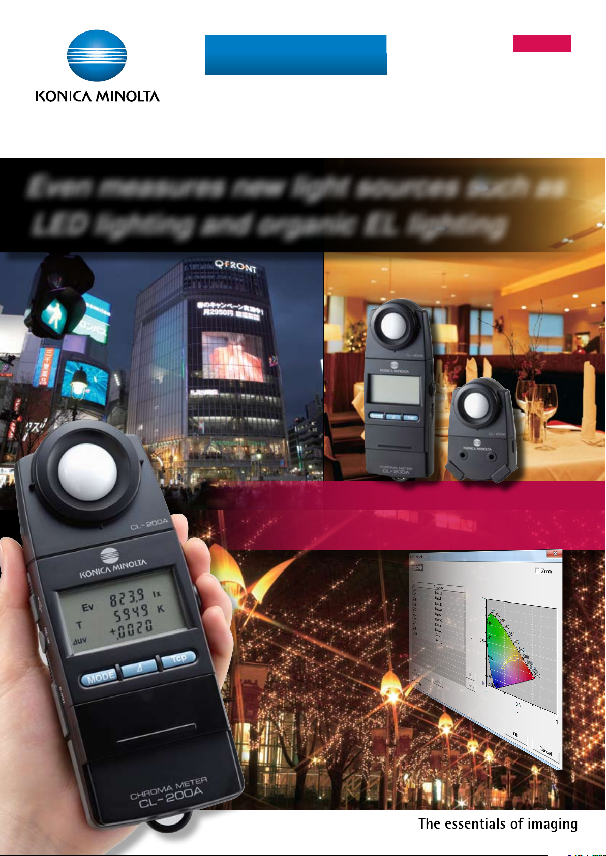
Chroma Meter
CL-200A
Even measures new light sources such as
LED lighting and organic EL lighting
A compact, lightweight instrument
with a detachable receptor. Includes
convenient, easy-to-use software.
Page 2
PASS
FAIL
PASS
FAIL
OK!
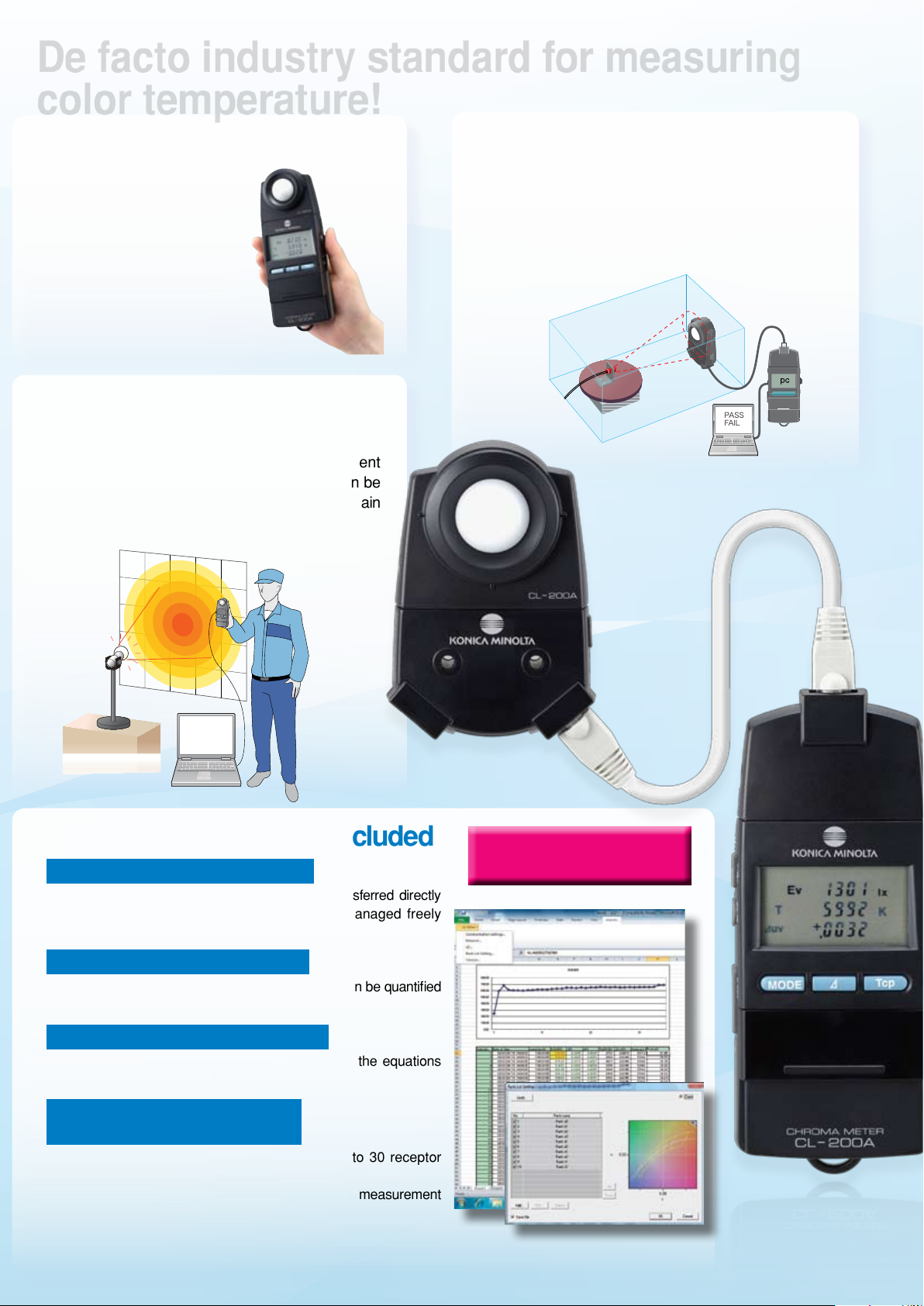
De facto industry standard for measuring
color temperature!
Compact and easy to carry
The CL:200A's compact
body fits in your palm.
Battery-powered so it can
be taken along and used
anywhere.
Data transfer using main
body buttons
When using the CL-200A with Data Management
Software CL-S10w (included), measurements can be
taken and data transferred to Excel® using the main
body buttons as well as computer keys.
Detachable receptor head
The receptor head can be detached and then
connected to the main body using a normal LAN
cable*, making it easy to install the sensor in an
inspection system.
Optional Adapter Units required for receptor head and
*
main body
Excel® add-in software included
Easy, convenient Excel® add-in
Measurement data from the CL-200A can be transferred directly
into Excel
within Excel
Includes LED ranking function
Color variations, the top topic in the LED industry, can be quantified
and a ranking function is also provided.
JIS correlated color temperature
Correlated color temperature is determined using the equations
defined by JIS (Japanese Industrial Standards).
Multi-point measurement and
user calibration also possible
Multi-point measurement management using up to 30 receptor
heads is possible.
User calibration function enables compensation of measurement
values to match a desired standard. Calibration can be performed
by two methods: Single-point calibration or RGB calibration.
®
. The transferred data can then be managed freely
®
.
Data Management Software
CL-S10w
(Standard accessory)
Page 3

Application
examples
Cross-section A
Illuminance (lx)
Horizontal distance (m)
Height (m)
0011223
3
4
-1-2-3
300
10 0
50
10
30
5
Wavelength (nm)
Can also measure illuminance
(JIS AA class)
Measures color
temperature!
Measures dominant
wavelength!
For lighting production and adjustment
When using various types of light sources in a room or open space, it is
sometimes necessary to check the color of the lighting.
By using the CL-200A, it is possible to adjust the lighting color so that the
food in a restaurant looks delicious.
For evaluating light source
characteristics
Evaluation of the light distribution of LED illumination modules or the
illuminance distribution of lighting fixtures can be evaluated.
Even measures
excitation purity!
For color-viewing cabinet maintenance
A color-viewing cabinet like that shown at left is used in industries such
as the printing industry to visually evaluate finished work under controlled
conditions. This color-viewing cabinet provides illumination at a specific
illuminance and color temperature by using fluorescent lamps, halogen
lamps, etc. The CL-200A can be used for the daily maintenance and control
of these lamps as well as to indicate when replacement is needed.
For projector light-source
research and color inspection
The CL-200A can be used to measure the white balance and uniformity of
microprojectors, etc. with internal LED light sources. The ability to connect
multiple receptors using LAN cables enables measurement of not only a
single point in the center, but up to a maximum of 30 points over the entire
projected area.
For LED billboard development
and maintenance
The CL-200A enables quality control of the LED modules for digital signage
to be performed easily. If modules with different color tones are used
together, the billboard will look mottled, but by measuring the chromaticity
and color temperature of modules using the CL-200A and selecting
modules based on measured values, billboard uniformity can be achieved.
Page 4

For accurate measurements of color temperature, use the CL-200A!
0.50
0.40
0.45
0.35
0.30
0.25
0.20
0.25 0.30 0.35 0.40 0.45 0.50 0.55
50000
+0.02uv
+0.01uv
0.00uv
0.01uv
0.02uv
30000
20000
15000
13000
10000
9000
8000
7000
6000
5000
4500
4000
3500
3000
2500
y
0.90
0.80
0.70
0.60
0.50
0.40
0.30
0.20
0.10
0.00
0.10 0.20 0.30 0.40 0.50 0.60 0.70
x
520
530
540
550
560
570
590
600
610
620
650
680〜780
510
500
490
480
470
460
450
380〜440
2000
2500
3000
3500
4000
4500
10000
*
*
*
*
*
*
B
C
A
D55
D65
D75
580
1500
Figure 1: Blackbody locus on xy
chromaticity diagram
Figure 2: Closeup of blackbody locus
on xy chromaticity diagram showing
correlated color temperature region
Measurement accuracies of CL-200A and photographic color meter
When measuring light sources with non-continuous spectrums such as LEDs, etc., accurate illumination color temperature is
particularly required. The CL-200A can measure color temperature accurately.
CL-2 00A
The CL-200A has sensors that closely match the color-matching functions defined by the CIE (International Commission on
Illumination), enabling precise color measurement. The measurement results can be displayed in various color notations such
as "Correlated color temperature and uv" according to the application.
Photographic color meter
In order to take more beautiful pictures, it is sometimes necessar y to attach filters in front of the camera lens to compensate
for the color of the light illuminating the subject. A photographic color meter is a meter used to select the appropriate filters,
with the sensitivity of its sensors adjusted to match that of the film or digital camera sensor. In addition, because it uses
photographic color temperature, which is calculated based mostly on the blue/red balance of the illumination, large errors
may occur if it is used to measure light sources with non-continuous spectrums.
[
Actual measurement data for daylight-color LED bulb
Our company's standard instrument
Measured color temperature
5045 0
]
Color-temperature difference from
standard-instrument measured value
CL-200A 50 11 -34
Photographic color meter 5600 555
Color temperature and correlated color temperature
Color temperature
When an ideal blackbody* is heated, it begins to emit light, and as the temperature increases the color of the emitted light
changes from red to yellow to white. Since the color of the emitted light is determined by the temperature of the blackbody,
the color of the light emitted by the blackbody can be expressed as the absolute temperature of the blackbody (in Kelvin).
This color notation scale is called "color temperature". For example, a 7000K color would be the color of the light emitted by
a blackbody heated to 7000K. Figure 1 shows the color of light emitted by a blackbody at various temperatures plotted on an
xy chromaticity diagram. This curve is called the "blackbody locus"; "color temperature" expresses a color on this blackbody
locus.
Correlated color temperature
Since the color of white light emitted by illumination equipment and displays is generally close to the blackbody locus, the
color of such light sources is normally expressed using "color temperature".
However, the color of such light sources is not directly on the blackbody locus. Because of this, a way to enable similar
color expression for colors within a larger region close to the blackbody locus was devised. This is called "correlated color
temperature", and the larger region is shown by the isotherms on the xy chromaticity diagram in Figure 2.
To accurately express the correlated color temperature of a light-source color, it is necessary to state not only the correlated
color temperature but the difference from the blackbody locus, normally in terms of
uv.
Blackbody
*
An ideal radiator. A body which completely
absorbs all incident electromagnetic
radiation. Although a perfect blackbody does
not actually exist, coal is a familiar object
that acts similarly.
Page 5

General Reference Information
LED Total Flux Measurement System
PC
Baffle
LED
LED holder
Integrating
sphere unit
Self-absorption
compensation LED
Constant-current
power supply
Spectroradiometer CS-2000
(modified for luminance measurement)
LED measurement
software
Illuminance (lx)
0
1
2
3
-1-2-3
300
10 0
50
10
30
5
Colors mix to create white light!
Blue light em itted by LED el ement
Yellow light emit ted by phos phor
Packag e
Electrode
Wavelength ( nm)
LED element
Phosphor
Waveleng th (nm)
Measurements in the LED manufacturing process
When made from blue LED and phosphor
The blue light emitted by the LED mixes with the yellow light
emitted by the phosphor to create white light.
Problem:
Since the spectral emission distribution of the
blue light emitted by the LED varies for each unit,
variations in the resulting white light will occur. Since
usually LED lamps use several LEDs, control of
color mixing is necessar y.
General solution:
Measure the spectral emission
➀
characteristics of each LED element
and rank them accordingly.
Measure the emission characteristics of the
➁
phosphor and rank accordingly.
Combine the ranked LED elements and ranked
➂
phosphor materials to achieve the desired white
light.
Inspect the output light quality of the final assembled white LED lamp.
➃
Variations in white light
How the CL-200A can help:
The CL-200A can measure the chromaticity from the phosphor and also
inspect the output light quality of the final assembled white LED lamp.
LED total flux measurement system
This system combines our top-of-the-line Spectroradiometer CS-2000 modified for illuminance measurement with an LED
❚
total flux measurement adapter to create an LED measurement system that utilizes a spectral measuring instrument
conforming to CIE 122-1996 as the receptor. The total flux emitted in all directions by the LED is diffused by the integrating
sphere and received for measurement by the spectroradiometer.
This system conforms to CIE 127:2007.
❚
Since the spectral response of the receptor matches the CIE spectral luminous efficiency function V(
❚
perform troublesome color correction.
To enable accurate measurements, a self-absorption compensation function is provided to compensate for the reduction
❚
in integrating sphere output due to self absorption of the light source when it is lit inside the integrating sphere.
λ
), there is no need to
Page 6

Certificate No : JQA-E-80027
Registration Date : March 12, 1997
Certificate No : YKA 0937154
Registration Date : March 3, 1995
For correct use and for your safety, be sure to read the instruction
manual before using the instrument.
s
Always connect the instrument to the specified power supply
voltage. Improper connection may cause a fire or electric shock.
s
Be sure to use the specified batteries. Using improper batteries
may cause a fire or electric shock.
SAFETY PRECAUTIONS
Certificate No : JQA-E-80027
Registration Date : March 12, 1997
Certificate No : YKA 0937154
Registration Date : March 3, 1995
KONICA MINOLTA SENSING, INC. Osaka, Japan
Konica Minolta Sensing Americas,Inc
New Jersey, U.S.A. Phone : 888-473-2656(in USA), 201-236-4300(outside USA) Fax : 201-785-2482
Konica Minolta Sensing Europe B.V.
European Headquarter /BENELUX
Nieuwegein, Netherlands Phone : +31(0)30 248-1193 Fax : +31(0)30 248-1280
German Oce München, Germany Phone :
+49(0)89 4357 156 0
Fax :
+49(0)89 4357 156 99
French Oce Roissy CDG, France Phone : +33(0)1 493-82519 Fax : +33(0)1 493-84771
UK Oce Milton Keynes, United Kingdom Phone : +44(0)1908 540-622 Fax : +44(0)1908 540-629
Italian Oce Milan, Italy Phone : +39 02 39011.425 Fax : +39 02 39011.223
Swiss Oce Dietikon, Switzerland Phone : +41(0)43 322-9800 Fax : +41(0)43 322-9809
Nordic Oce Västra Frölunda, Sweden Phone : +46(0)31 7099464 Fax : +46(0)31 474945
Polish Oce Wroclaw, Poland Phone : +48(0)71 33050-01 Fax : +48(0)71 734 52 10
Konica Minolta (CHINA) Investment Ltd.
SE Sales Division Shanghai, China Phone : +86-021-5489 0202 Fax : +86-021-5489 0005
Beijing Branch Beijing, China Phone : +86-010-8522 1551 Fax : +86-010-8522 1241
Guangzhou Branch Guangzhou, China Phone : +86-020-3826 4220 Fax : +86-020-3826 4223
Chongqing Office Chongqing, China Phone : +86-023-6773 4988 Fax : +86-023-6773 4799
Qingdao Office Qingdao, China Phone : +86-0532-8079 1871 Fax : +86-0532-8079 1873
Konica Minolta Sensing Singapore Pte Ltd. Singapore Phone : +65 6563-5533 Fax : +65 6560-9721
KONICA MINOLTA SENSING, INC. Seoul Office Seoul, Korea Phone : +82(0)2-523-9726 Fax : +82(0)2-523-9729
http://konicaminolta.com/instruments/about/network
Addresses and telephone/fax numbers are subject to change without notice. For the latest contact information,
please refer to the KONICA MINOLTA SENSING Worldwide Offices web page :
<Standard accessories>
*
Not included as standard accessory in some areas.
<Optional accessories>
CL-200A
AA Battery (2pcs.)*
Strap
Case T-A10
Cap T-A13
PC
(commercially
available)
Printer
(commercially available)
Data Management Software
CL-S10w
Processing by computer
Printing out data
USB Cable
T-A15 (2m)
Printer Cable
T-A12 (2m)
AC Adapter
External Power
CL-200A
*
Receptor Head
Hood CL-A11
Optional receptor head
For CRT
Measurement
Adaptor Unit for
Main Body
T-A20
Adapter Unit for
Receptor Head
T-A21
With LAN category-5 cable 1m
For Multi-Point Measurement / Detached Head
LAN(10BASE-T )
category-5 straight cable
(commercially
available)
Multi-point measurement requires use of optional AC adapter.
Hard Case
CL-A10
*
CL-200
receptor
head can
also be used.
Ex.: Multi-point
measurement
Ex.: Head and body
connected via
cable
Reference plane
Center of re cepto r
window
Tripod soc ket
7. 5
7. 5
(71.8)
30
(56.3)(46.3)
φ4.5
hole
φ45.2
50
35
69 30
35
27. 5
174
φ25
φ45.2
56.318
13
25
SYSTEM DIAGRAM
Main specifications of Chroma Meter CL-200A
Model Chroma Meter CL-200A
Luminance meter
class
Relative spectral
response
Cosine response
Conforms to requirements for Class AA of JIS C 1609 -1: 2006 "Illuminance
meters Pa rt 1: General measuring instruments"
Closely matches CIE Standard Obser ver cur ves x(
Within 6% (fi') of the CIE spectral luminous efficency V ( )
(f2) Ev: Within 3%
- --
), y( ), and z( )
DIMENSIONS
With receptor head attached to main body
(Units:mm)
Receptor Silicon photocell
Measuring function Tristimulus values : XYZ
Chromaticity: E
Correlated color temperature: EvTcpuv; Tcp(JIS method; available only with
CL- S10 w)
Color difference:
xy; Evu'v'; Ev, Dominant wavelength, Excitation purit y
v
(XYZ), (Evxy), (Evu'v'), Evu'v'(Target : 1)
Other function User calibration function, Data hold function, Multi-point measurement (2 to 30 points)
Measuring range 0.1 to 99,990 lx, 0.01 to 9,999 fcd (Chromaticit y : 5 lx, 0.5 fcd or above ) in
Accuracy E
Repeatability
Temperature drift Ev: ±3% ±1digit of displayed value, xy: ±0.003 ( Based on Konica Minolta's
Humidity drif t Ev: ±3% ±1digit of displayed value, xy: ±0.003 ( Based on Konica Minolta's
four automatically selected ranges ( lx or fcd is switchable)
v (Linearity)
xy: ± 0.002
Ev: 0.5%+1digit (2σ),
xy: ± 0.0005
: ±2%±1digit of displayed value
(800 lx, Standard Illuminant A measured )
(800 lx, Standard Illuminant A measured )
standard measurement conditions)
standard measurement conditions)
With Adapter Unit attached to receptor head
Response time 0.5 sec. (continuous measurement)
Digital output USB
Display 4-significant-digit LCD with back-light illumination
Operating temperature/
humidity range
Storage temperature
/ humidit y range
Power source 2 AA-size batteries / AC adapter (optional)
Batter y life 72 hours or longer ( When alkaline batteries are used ) in continuous measurement
Dimensions 69×174×35mm (2-6/16×6-14/16×1-7/13in.)
Weight 215g (7.6 oz.) not including bat teries
Standard
accessories
Optional
accessories
-10 to 40˚C, relative humidit y 85% or le ss (at 35˚C) with no condensation
-20 to 55˚C, relative humidit y 85% or le ss (at 35˚C) with no condensation
Case T-A10, Cap T-A13, Strap, A A Batte ries ( 2)*, Data Mane gement Software
CL-S10w, USB cable T-A15
Receptor Head, Adaptor Unit for Main Body T-A20, Adapter Unit for Receptor Head T-A21,
AC Adapter AC-A308 (For 1 to 10 receptor heads),
AC Adapter AC-A311 (For 1 to 30 receptor heads),
Printer Cable T-A12, Hood CL-A11, Hard Case CL-A10
Not incl uded as stand ard acc esso ry in s ome are as.
*
•KONICAM INOLTAandtheKoni caMinolt alogoan dthesymbo lmark,a nd
"The ess ential s of imagin g" are regi stered tr ademarks or trad emarks of
KONICA MINO LTA HOLDINGS , INC.
•Win dows® and Exce l® are trade marks of Microso ft Corp oration in the USA
and other c ountries.
•Thes pecic ationsa nddrawi ngsgivenh erearesu bjecttoch angewit hout
prior not ice.
•Scr eenssho wnareforil lustra tionpur poseonl y.
Main specifications of Data Management Software CL-S10w
Typ e Add-in for Excel® * Excel is require d to use this add-in.
Operating
environment
Compatible instruments
One of the following environments with Excel
®
Windows
Windows
*
*
CL- 20 0A, CL-200* * Some functions not usable with CL-200.
XP + Excel® 2003 ( English, Japanese, or Simplified Chinese)
®
7 + Excel® 2007 (English, Japanese, or Simplified Chinese)
For detail s on sys tem requi rement s f or a bove versi ons of Windows®and/ or Excel®,
refer to th eir resp ectiv e speci ficatio ns.
Langu ages in pa renth esis ( ) ar e the OS lan guage.
©2010 KONICA MINOLTA SENSING,INC.
®
installed:
9242-4876-12 BAGAPK➀Printed in Japan
 Loading...