

Page 1
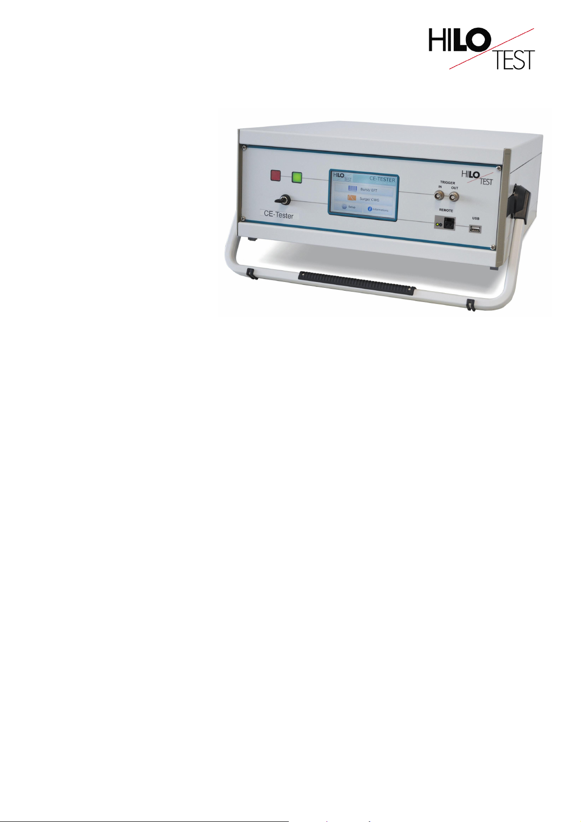
CE - TESTER
Compact EMC-tester
acc. to the standards:
BURST 5kV:
IEC 61000-4-4 : 2012
SURGE 5kV, 2.5kA:
IEC 61000-4-5 : 2007
Magnetic field 50/60 Hz:
IEC 61000-4-8 : 2010
Magnetic field 8/20 µs:
IEC 61000-4-9 : 2001
Voltage dips/variation:
IEC 61000-4-11 : 2004
The CE-TESTER is a compact EMC test unit designed for testing electromagnetic immunity
against pulsed and conducted interference. Demonstrating such immunity is generally a
requirement for compliance with the European EMC directive, a necessary step leading to the
CE mark.
In its basic configuration, the CE-TESTER includes an Electrical Fast Transient Generator
(EFTG), a Combination Wave Generator (CWG) and a Coupling-/Decoupling Network (CDN)
for single-phase power supply lines.
The Electrical Fast Transient Generator fully compliant to IEC 61000-4-4, delivers fast
transient pulses with waveform 5/50 ns and a maximum burst frequency of 1 MHz. It is used
for immunity testing of electronic systems and devices. The four standard IEC 61000-4-4 test
levels may be easily selected by push button or all parameters may be adjusted individually.
The Combination Wave Generator fully compliant to IEC 61000-4-5 and IEEE 587 delivers a
standard impulse voltage with waveform 1.2/50 µs and a standard impulse current with
waveform 8/20 µs. It is a combined impulse-current-/impulse-voltage generator for highimpedance loads RL > 100Ω and may be used for surge testing of components and devices,
as well as for galvanic coupling of surges to cable shields, shielded enclosures and cabinets.
The built-in capacitive Coupling-/Decoupling Network allows superimposition of the
combination wave generator output to the mains voltage of the device under test.
The simulation of voltage dips and voltage variations acc. to IEC 61000-4-11 can be included
as a option. Additional accessories allow the testing of immunity against both pulsed and
power frequency magnetic fields according to IEC 61000-4-8 and IEC 61000-4-9.
Technical specifications subject to change, CE_TESTE_3G.DOC, 10/12
HILO-TEST GmbH, Am Hasenbiel 42, D-76297 Stutensee-Karlsruhe, Tel. 07244/20500-0, www.hilo-test.de
Page 1/3
Page 2

Optionally the CE-TESTER can include a trigger able power supply switch which allows the
simulation of the voltage dips as specified in the standard IEC 61000-4-11. The variation of
power supply voltage is controlled by use of an external motor driven variac. The control of
the external power source is included in the mainframe.
An Induction Coil in conjunction with the Combination Wave Generator output, is used to
simulate pulsed magnetic fields according to IEC 61000-4-9. Combined with the external
power source, the Induction Coil can be used to simulate power frequency magnetic fields
according to IEC 61000-4-8.
Additional Coupling-/Decoupling Networks covering three-phase power supply lines, DC
supply lines and signal lines are also available, as well as a Capacitive Coupling Clamp for
coupling to shielded interconnection lines.
The CE-TESTER excels by its compact design, simple handling and precise reproducibility of
test impulses. It features a microprocessor controlled user interface and a 5” touch screen
unit for ease of use. The microprocessor allows the user to execute either standard test
routines or a “user defined ” test sequence. A standard USB port provides the ability to print a
summary of the test parameters to a USB stick.
The software program CE-REMOTE allows full remote control of the test generator via
Ethernet light guide as well as documentation and evaluation of test results, accordingly to
the IEC 17025. To record definite impulses, it is equipped with an Impulse Recording
Function (IRF)
Moreover all generator functions including the built-in Coupling-/Decoupling Network, may be
computer controlled via the isolated optical interface.
Technical specifications subject to change, CE_TESTE_3G.DOC, 10/12
HILO-TEST GmbH, Am Hasenbiel 42, D-76297 Stutensee-Karlsruhe, Tel. 07244/20500-0, www.hilo-test.de
Page 2/3
Page 3

TECHNICAL SPECIFICATIONS CE-TESTER
Mainframe
Microprocessor controlled touch panel 5”, 800X480, 24 bit
Optical Ethernet Interface for remote control of the generator optional
Interface for saving reports USB
External trigger input /output
Coupling-/decoupling network for power supply lines L1, N, PE
Nominal voltage, nominal current
Coupling impedance (depending on the generator)
Connector for external safety interlock loop 24 V =
External red and green warning lamps 230 V, 60W
Mains power 230 V, 50/60 Hz
Dimensions of desk top case W * H * D 450*185*500 mm3
Weight 25 kg
BURST acc. to IEC 61000-4-4: 2011
Pulse output voltage, adjustable 0.2 - 5.0 KV ± 10 %
Waveform 5/50 ns
Source impedance
Polarity, selectable pos/neg/alt
Burst frequency, adjustable 1.0 kHz - 1.0 MHz
Burst duration, adjustable 0,01 ms - 25 ms
Burst repetition rate, adjustable 10 ms - 1000 ms
HV output for external coupling devices coaxial
Monitor output for pulse output voltage
SURGE acc. to IEC 61000-4-5: 2007
Test voltage (open circuit condition) 0.2 – 5.0 kV ± 10 %
Waveform acc. to IEC 60060 1.2 / 50 µs ± 20 %
Test current (short circuit condition) 0.1 - 2.25 kA ± 10 %
Waveform acc. to IEC 60060 8 / 20 µs ± 20%
Polarity of output voltage/current, selectable pos/neg/alt
Maximum stored energy 120 Joule
Charging time for max. charging voltage < 10 s
HV output isolated from ground HV-OUT, 4mm
Mains synchronous triggering, phase shifting, digitally selectable 0 - 359°, step 1°
Monitor output for pulse output voltage ratio = 1000 : 1 ± 5%
Monitor output for pulse output current
Option: Software CE-REMOTE Test, for remote control
With Impulse Recording Function (IRF)
( XP, WIN7 ) incl. 5 m fibre optic cable and PC Ethernet interface
POWER FAIL acc. to IEC 61000-4-11: 2004
Rated current / Inrush current, max. 16 A / 500A
Monitor output for mains voltage and mains current built-in
Display of mains voltage, mains current and inrush current
Interface for control of an external power source
Option: External power source VPS 250-16
Output voltage, adjustable 0 - 250 V
Rated current 16 A
Control via interface of CE-TESTER
Option: Induction Coil HI 100 acc. to IEC 61000-4-8/9: 2010/2001
Dimensions 1000*1000*600 mm3
Coil factor 1.0 ± 10%
10 V at 1 kΩ
250 V, 16 A ≈ / 10 A =
33 nF / 18 µF / 9µF+10Ω
50 Ω
ratio = 100:1 ± 5%, 50 Ω
10 V ≡ 5 kA ± 5%
Technical specifications subject to change, CE_TESTE_3G.DOC, 10/12
HILO-TEST GmbH, Am Hasenbiel 42, D-76297 Stutensee-Karlsruhe, Tel. 07244/20500-0, www.hilo-test.de
Page 3/3
Page 4

System configuration
The CE-TESTER and its sub-units are available in different configurations:
CE-TESTER 1 including SURGE and BURST
CE-TESTER 2 including SURGE, BURST and POWER FAIL SWITCH
EFTG 4510 Stand alone BURST generator
CE-SURGE Stand alone SURGE generator
PFS 2516 Stand alone POWER FAIL SIMULATOR
Including a power fail switch and a variable power source
Typical configurations:
CE-TESTER 1 +CDN 4416 for 3-phase testing
CE-TESTER 2 +VPS 250-16 for testing surge, burst, power fail, voltage dips and variation
It is possible to build all devices in a 19” rack cabinet.
Technical specifications subject to change, CE_TESTE_3G.DOC, 10/12
HILO-TEST GmbH, Am Hasenbiel 42, D-76297 Stutensee-Karlsruhe, Tel. 07244/20500-0, www.hilo-test.de
Page 4/3
 Loading...