

Page 1
Features
Frequency Range - 150 kHz - 80 MHz
Meets EN 61000-4-6 requirements
Current Rating: up to 25 Amps
Individual Calibration
Two Year Warranty
Coupling / Decoupling Networks
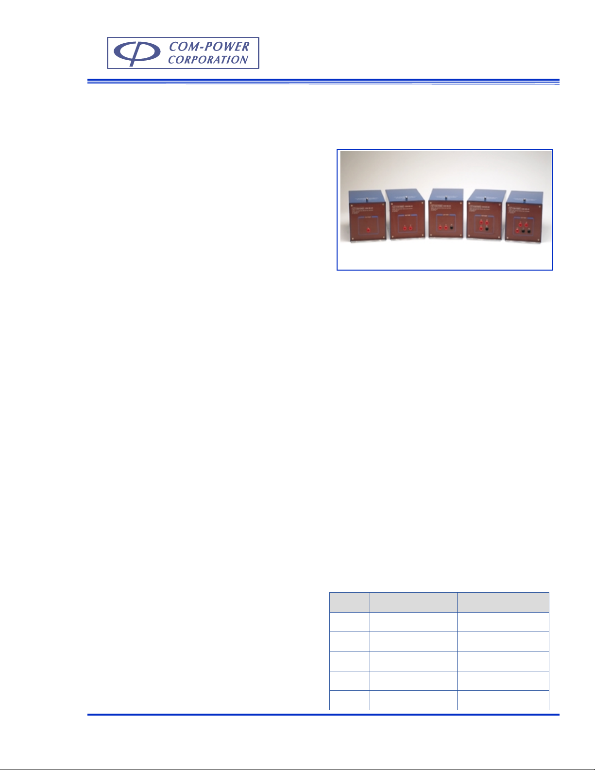
M Series
Models
CDN-M125, M225, M325, M425, M525
Description
The M series powerline Coupling / Decoupling Networks (CDN) are for testing from 150 kHz - 80 MHz
according to the EN 61000-4-6 standard for immunity
to conducted disturbance induced by radio frequency
fields. The standard M series CDNs are a vailable with
25 amperes current rating.
The coupling network deliv ers injected common mode
current disturbance signals through the power line conductors to the equipment under test (EUT). The
decoupling networks are used to ensure that the disturbing signals injected on the powerline of the EUT
by the coupling networks do not interfere with any of
the auxiliary equipment connected to the EUT. Each
CDN contains integrated direct capacitive coupling
along with a high impedance choke for inductive
decoupling.
All CDNs are individually calibrated to meet the impedance requirement of EN 61000-4-6. However, test
level calibration must be performed on site to determine the minimum required test signal needed to
achieve the required voltage levels specified by EN
61000-4-6. The appropriate calibration accessories for
conducting the test is available from Com-Power.
Application
During the test, the CDN is connected to the powerline
cables between the equipment under test (EUT) and
auxiliary equipment (AE). The number of conductors
in the cable will determine which CDN to use for the
test.
The M125 CDN is used to couple common mode and
modulated signals onto single power line systems. This
CDN is ideal for electronic systems that uses the chassis as the DC return. The M225 CDN is for systems
with two wire power conductor cables without an earth
terminals and the M325 is for single phase two line
cables with the an earth ground conductor. The M425
is used for three phase systems. The M525 CDN is used
for three phase systems with neutral and protected earth
ground conductors. All CDNs are also fitted with safety
sockets for connecting the devices under test.
CDN selection table
ledoM
521M
-NDC
522M-NDC522 laruten+esahpelgniS
-NDC
523M
tnerruC
)spmA(gnitaR
521enilelgniS
523 htrae+laruten+esahpelgniS
forebmuN
seniL
noitacilppA
524M-NDC524 htrae+esahpeerhT
-NDC
525M
Com-Power Corporation (949) 587 - 9800 www. com-power.com sales@com-power.com
525 htrae+laruten+esahpeerhT
E-9
Page 2

Specifications
Frequency Range: 150 kHz - 80 MHz
Voltage rating: 480 V AC
600 V DC
Current rating: 25 Amperes
Common mode impedance: 150 kHz - 26 MHz: 150 Ohms ± 20 Ohms
26 MHz - 80 MHz: 150 Ohms + 60 Ohms and - 45.5 Ohms
Maximum RF voltage input: 40 V max
Voltage attenuation (RF/EUT): 9 dB to 12 dB
Insertion loss EUT/AE: 30 dB min from 150 kHz to 2 MHz
50 dB min from 2 MHz to 80 MHz
Coupling factor: 0.3 dB max up to 3 kHz
Decoupling attenuation (RF/AE): 50 dB min, 150 kHz - 80 MHz
AE & EUT connector type: 4 mm Safety Sockets
RF (Disturbance coupling) connector: BNC (f) 50 Ohm
Dimensions (inches): 6 x 6 x 12.5 (all models)
Weight (all model): 5 lbs. max.
Test level calibration components selection table:
ledoMnoitarbilaC
etpadAr
)EA(tupnI
521M-NDC521M-ADA521M-ADA050-PET&515-ADA515-ADA
522M-NDC522M-ADA522M-ADA050-PET&515-ADA515-ADA
523M-NDC523M-ADA523M-ADA050-PET&515-ADA515-ADA
524M-NDC524M-ADA524M-ADA050-PET&515-ADA515-ADA
525M-NDC525M-ADA525M-ADA050-PET&515-ADA515-ADA
noitarbilaC
etpadAr
)TUE(tuptuO
edoMnommoC
rofsretpadA
)EA(tupnI
edoMnommoC
rofsretpadA
)TUE(tuptuO
Typical impedance graph for all models compared to the EN 61000-4-6 requir ements
300
250
200
Max Limit
150
100
Min Limit
Impedance (Ohms)
50
0
0.1 1 10 100
All values are typical unless specified.
All specifications are subject to change without notice.
Com-Power Corporation 20621 Pascal Way, Lake Forest, California 92630 (949) 587 - 9800 www.com-power.com Rev 0102
E-10
Frequency (MHz)
 Loading...