

Page 1
BGL
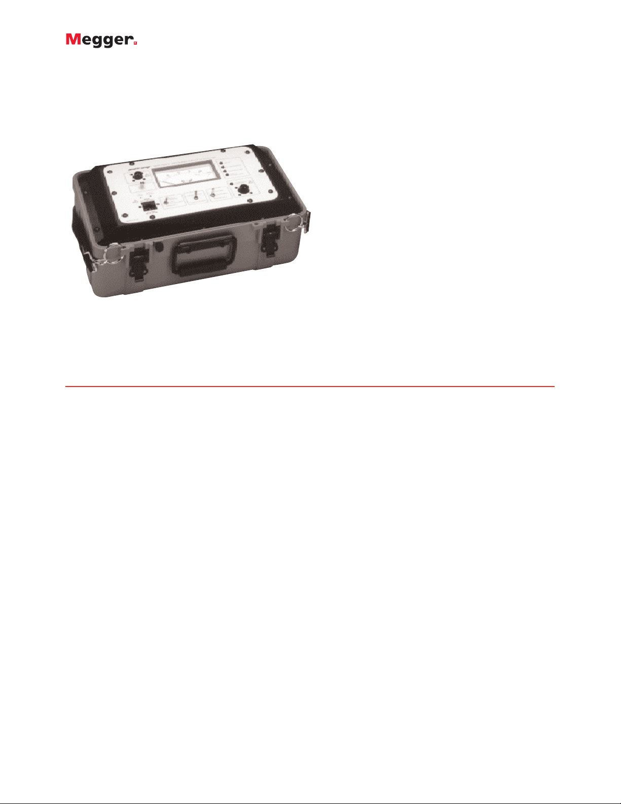
Battery Ground-Fault Locator
■
Locates ground faults on floating
battery systems
■
Operates on live battery systems
■
Multiple fault detection and tracking
■
Automatic operation
■
Battery operated
BGL
Battery Ground-Fault Locator
DESCRIPTION
The Battery Ground-Fault Locator (BGL) simplifies the
tracking of ground faults on floating dc-powered control
systems.
It features automatic operation, can be used on live battery
systems and has the unique capability of detecting,
tracking and locating multiple faults on a battery system
without having to resort to sectionalizing.
This is accomplished by injecting a low- amplitude 25
Hertz test signal on either the positive or negative side of
the power bus and tracking the signal with one of several
available clamp-on sensor pr
A fault simulator also is provided with the instrument,
allowing the periodic verification of the resistance and
capacitance ranges of the BGL.
APPLICATIONS
The BGL allows tracking and locating of ground faults on
live or dead battery systems. Its locating ability is only
limited by the accessibility of the battery cable.
The instrument can make measurements in the presence of
dc current (up to 20 amperes) and ac ripple (charging
current up to 0.5 ampere).
The BGL is useful for locating grounds on any type of
battery system, including those in r
utilities as well as UPS and continuous process systems.
The BGL operates on battery systems that are either
floating or grounded through a resistor. Operators can
obes.
efineries, mines and
determine both the direction and magnitude of faults,
allowing them to ignore high-impedance faults and
concentrate on serious faults.
The BGL is designed to work on battery systems up to 260
volts dc. The instrument even operates in the presence of
surge-suppression capacitors, effectively ignoring them. It
is only sensitive to the power dissipated in the grounding
resistance, hence the resistive paths to ground.
An additional feature of the BGL is its ability to measure
battery system total capacitance to ground, or the
capacitors of any branch of the system. This allows the
operator to deter
resistance range and provides the user with information on
the battery system.
PRINCIPLE OF OPERATION
The instrument operates by injecting a 25 Hertz signal
between the battery system and the ground. The resulting
current is tracked by a clamp-on current probe. The
magnitude of the injected signal is only 3.5 volts and will
not cause any inter
protective relays on the system.
The instrument’s circuitry measures the 25 Hertz power
dissipated in the grounding resistance and calculates the
value of the grounding resistance from knowledge of the
applied voltage.
This method allows the instrument to ef
fects of charging current due to capacitance on the
the ef
battery system or surge suppression capacitors that may be
installed on the system.
mine the maximum practical fault-
ference with the operation of sensitive
fectively eliminate
Page 2

attery Ground-Fault Locator
B
BGL
The wide dynamic range of the instrument allows the
perator to simultaneously track two or more ground
o
faults that may be different in value. The injected signal is
low enough in amplitude that it should not interfere with
the operation of relays, even of the sensitive variety, under
normal operation.
EATURES AND BENEFITS
F
■
Reads resistance directly (1 ohm to 100 kilohms)
■
ocates single or multiple ground faults
L
■
perates on floating or resistance-grounded battery
O
systems
■
Operates on live battery systems
■
Operates in the presence of surge-correction capacitors
■
Fused output leads for maximum user safety
■
Battery operated with internal automatic charger
■
Measures capacitance
■
Lightweight and portable
■
Tough polyethylene plastic sealed enclosure that
provides high shock and vibration resistance
ORDERING INFORMATION
Item (Qty) Cat. No.
Battery Ground-Fault Locator
120 volt, 60 Hz 835140
240 volt, 50 Hz 835140-1
220 volt, 60 Hz 835140-2
120 volt, 50 Hz 835140-3
Included Accessories
Clamp-on current sensor, 33 ft (10 m),
2 in. (50 mm) opening – max dc current: 20 A [1] 835142
Fault simulator [1] 835145
Output lead extension, 14.9 ft (4.5 m) [1] 835144
Output lead, 6.6 ft (2 m) [1] 835143
Power cord, ac 17032
Instruction manual [1] AVTM835140
Optional Accessories
Mini clamp-on current sensor, 0.5 in. (127 mm)
opening – max dc current: 5 A 835146
Busbar clamp-on sensor, 2 x 4 in. (50 x 101 mm)
opening – max dc current: 50 A 835147
SPECIFICATIONS
Input (specify one)
120 V, 60 Hz, 30 VA OR 240 V, 50 Hz, 30 VA
Battery
Lead-acid rechargeable
Resistance Range
1 Ω to 100 kΩ
Capacitance Range
1 to 100 µF
Accuracy
±15% to ±40%
Accuracy depends on resistance/capacitance load
Injected Signal
25 Hz nominal, 3.5 V rms maximum, 110 mA maximum
Maximum Ripple Current
0.5 A (ac)
Environmental
Operating Temperature
32 to 122° F (0 to 50° C)
Storage Temperature
-40 to +149° F (-40 to +65° C)
Relative Humidity
Up to 80%
Dimensions
13 H x 14 W x 10 D in. (330 H x 356 W x 254 D mm)
Weight
25 lb (11.3 kg)
UK
Archcliffe Road, Dover
CT17 9EN England
T +44 (0) 1 304 502101
F +44 (0) 1 304 207342
UKsales@megger.com
UNITED STATES
onze Way
4271 Br
Dallas, TX 75237-1019 USA
T 1 800 723 2861 (USA only)
T +1 214 333 3201
F +1 214 331 7399
USsales@megger.com
OTHER TECHNICAL SALES OFFICES
Täby SWEDEN, Norristown USA,
Sydney AUSTRALIA, T
Trappes FRANCE, Kingdom of BAHRAIN,
Mumbai INDIA, Johannesburg SOUTH
AFRICA, and Chonburi THAILAND
onto CANADA,
or
TEMENT
A
ISO ST
Registered to ISO 9001:2000 Cert. no. 10006.01
BGL_DS_en_V11
www.megger.com
Megger is a registered trademark
 Loading...