

Page 1
Features & Benefits
250 MS/s Clock Rate
Provides up to 125 MHz
Waveforms
256 k Memory Depth
12-Bit Vertical Resolution
Direct DSO
Waveform Transfers
Region Shift Function
Provides 4 ps Edge
Placement
Optional 12-Bit 250 MHz
(ECL) or 12/24-Bit 100 MHz
(TTL) Digital Data Generator
Built-in 1.4 MB, 3.5 in.
Floppy Disk
FFT Frequency Domain
Editor (Opt. 09)
Real-time Waveform
Sequencer to Easily Create
Automatic Test Sequences
and Extremely Long Patterns
Formula Entry of Waveforms
Channel Summing
(with Opt. 02)
Fully Programmable from
Front Panel, RS-232 and
GPIB (IEEE-488.2)
Applications
Analog and Digital Modulation
Wireless Communication
All Forms of Fading Simulation
Navigation
I and Q Impairment
Audio
Computer Peripherals
Automotive
D/A and A/D
Converter Testing
Filter Design
Semiconductor Logic
(ASIC/DSP/FPGA)
CCD, LCD
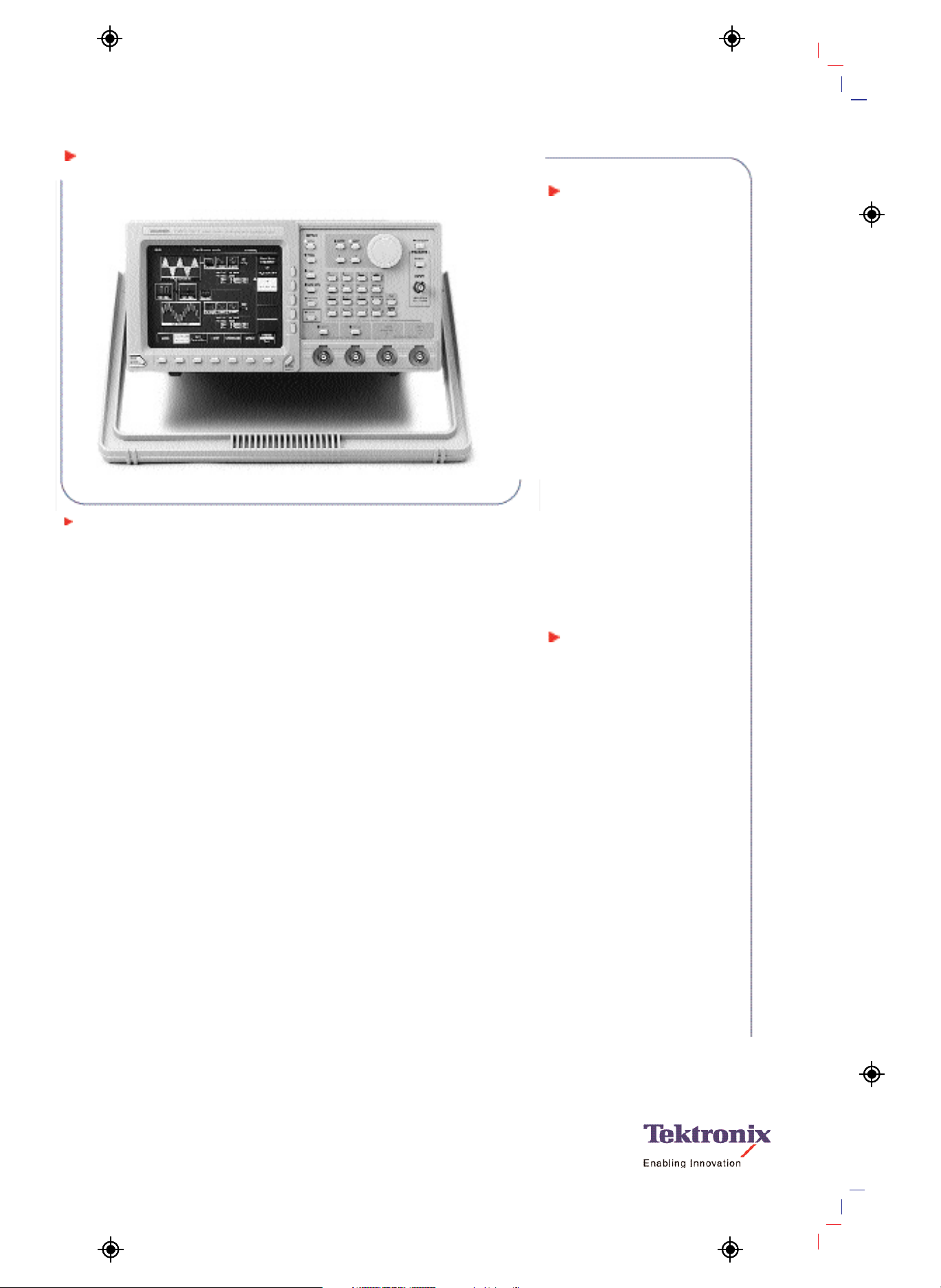
Arbitrary Waveform Generator
AWG2021
AWG2021.
Arbitrary Waveform Generators
•
www.tektronix.com/signal_sources
1
The AWG2021 offers 250 MS/s and 256 k
deep memory. As with the entire AWG2000
Series, the graphical user interface allows
on-screen viewing of waveform editing, sim-
plifying “what if” test scenarios by allowing
the easy creation of composite signals.
The standard AWG2021configuration pro-
vides one 5 V output or a second independ-
ent 5V output (Opt. 02) each with 12-Bit
vertical resolution. Frequency of channel 2
is also independently programmable.
Option 03 adds a 12-Bit wide differential
ECL digital port which can be used in con-
junction with the marker outputs for data
generation up to 14 Bits wide at up to
250 MHz. Or if you prefer, Option 04 provides
TTL digital levels with up to two 12-Bit,
100 MS/s ports for a total of 28 Bits wide.
The built-in frequency domain (FFT) editor
(Opt. 09) is a perfect addition for customers
performing proprietary or standard modula-
tion simulations, filter design or in physical
layer testing. Real-time waveform sequencing
extends the effective record length output
to over a billion points!
The AWG2021 easily simulates signals
where moderate point definition and long
records are required for simulating very
complex waveform conditions. Direct wave-
form transfer capability makes the AWG2021
the perfect complement to selected
Tektronix oscilloscopes.
Page 2

Arbitrary Waveform Generators
•
www.tektronix.com/signal_sources
2
Arbitrary Waveform Generator
AWG2021
Characteristics
Standard Waveshapes
Sine, square, triangle, ramp, pulse, arbitrary, linked
sequence and DC.
Arbitrary Waveforms
Execution Memory –
Waveform: 256 Kwords.
Marker: 256 Kwords x 2 Bits.
Data Points of Waveform Size: 64 to 256 K
in multiples of 8.
Real-time Sequencer Memory –
8 K individual waveforms.
Loop Counter: 1 to 65,535 repeats.
Burst Mode Counter: 1 to 64 K cycles.
Catalog Memory Clock
Frequency Range – 10 Hz to 250 MHz.
Resolution – 4 digit.
Accuracy – 50 ppm (+15 ºC to +30 ºC).
Skew between CH. 1 and CH. 2 (Opt. 02 only) –
Within 4 ns.
Operating Modes
Continuous – Output continuous at programmed
waveshape, frequency, amplitude and offset.
Triggered – Output quiescent until triggered by
an external, GPIB or manual trigger; then generates
a sequence only one time.
Gated – Same as triggered mode except period is
executed only for the duration of the gated signal
until the sequence started is completed.
Burst – Output quiescent until triggered by an
external, GPIB or manual trigger; then generates
“n” sequences or cycles.
Waveform Advance – Continuously generates the
waveform in a predefined sequence; the next trigger advances to the next waveform in sequence.
Autostep – Generates the predefined waveform
once in the Autostep File; the next trigger advances
the waveform.
Main Output
Amplitude (Excluding ADD and Multiply
Operation) –
Digital-to-Analog Resolution: 1/4096 (12-Bit).
Range: 0.05 V to 5 V
p-p
into 50 Ω DC.
Accuracy: 0.05 V to 0.5 V, ±(0.5% of amplitude
+5 mV); 0.501 V to 5 V, ±(1% of amplitude
+25 mV).
Offset –
Range: –2.5 V to +2.5 V into 50 Ω, (–100 mA to
+100 mA).
Resolution: 0.2 mA.
Accuracy: ±(1% of offset +0.2 mA).
Pulse Response –
15 ºC to +30 ºC: Flatness, within 3% after 20 ns
from rise/fall edges; Aberrations, within 7% +10 mV.
+10 ºC to +40 ºC: Rise/Fall time, <4.2 ns; flatness,
within 5% after 20 ns from rise/fall edges; aberrations, within 9% +10 mV.
Impedance – Typically 50 Ω.
Sinewave (Amplitude 1 V, 100 kHz Reference) –
Flatness: Within 4%.
THD: 1.0 V, ≤50 dBc, 0.5 V, ≤66 dBc.
Spurious: ≤66 dBc.
Channel Summing
(Opt. 02 only)
AM (Multiply) –
Output: Within 5%.
Frequency Response: DC to 30 MHz.
External AM –
Sensitivity: 2 V
p-p
(±5%) signal produces
100% modulation.
Frequency Response: CH 1, DC to 30 MHz;
Ext. Signal, DC to 4 MHz.
Add –
Output: Within 5%.
Frequency Response: DC to 30 MHz.
Filters
3 dB Cutoff Frequency –
1 MHz: Within 20%.
5 MHz: Within 20%.
20 MHz: Within 20%.
50 MHz: Within 20%.
Delay –
1 MHz: Typically 390 ns.
5 MHz: Typically 78 ns.
20 MHz: Typically 18 ns.
50 MHz: Typically 11 ns.
Auxiliary Outputs
Markers 1 and 2 –
Amplitude:
Marker 1 >1.2 V into 50 Ω, >2.4 V into
open circuit.
Marker 2 >1.2 V into 50 Ω, >2.4 V into
open circuit.
Impedance: 50 Ω.
Marker to Signal Delay: Within 15 ns.
Sync –
Amplitude: >1.2 V into 50 Ω, >2.4 V into
open circuit.
Impedance: 50 Ω.
Sync to Signal Delay: Within 15 ns.
Clock –
Amplitude: 1 V ±0.3 V into 50 Ω.
Impedance: 50 Ω.
Digital Data Out (Opt. 03, eliminates RS-232
Interface) –
Level: Differential ECL compatible.
Output Signals: Data (D0 to D11).
Skew Between Data: Within 1 ns.
Clock to Data Delay: Within 3 ns.
Connector: 68-Pin mini-D sub.
Auxiliary Inputs
Trigger –
Threshold Level: –5 V to +5 V.
Resolution: 0.1 V.
Accuracy: ±(5% x Level + 0.1 V).
Pulse Width: 15 ns minimum.
Input Swing: 0.2 V minimum.
Maximum Input Volts: 10 V
p-p
when 1 MΩ selected;
5V
RMS
when 50 Ω selected.
Impedance: 1 MΩ with 30 pF max.
Trigger to Output Signal Delay: External clock,
100 ns maximum +1 clock.
Trigger Holdoff – 5µs maximum.
AM (Opt. 02 only) –
Range: 2 V
p-p
(–1 V to +1 V) for 100% modulation.
Maximum Input: ±5 V
p-p
,10kΩ impedance.
System Clock –
Threshold Level: 0.3 V ±0.1 V.
Input Swing: 0.8 V minimum.
Pulse Width: 2 ns minimum.
Maximum Input Voltage: ±2 V
p-p
.
Impedance: 50 Ω.
Frequency Range: Up to 250 MHz phase coherent.
Programmable Interface
GPIB – IEEE 488.2-1987 compatible.
RS-232 – 9-Pin D connector.
Page 3

Arbitrary Waveform Generator
AWG2021
Environmental
Temperature –
Operating: +10 ºC to +40 ºC.
Nonoperating: –20 ºC to +60 ºC.
Temperature Change –
Operating: +15 ºC per hour (no condensation).
Nonoperating: +30 ºC per hour (no condensation).
Humidity –
Operating: 20% to 80% (no condensation).
Nonoperating: 5% to 90% (no condensation).
Altitude –
Operating: To 4.5 km (15,000 ft.). Maximum operating temperature decreases 1 ºC for each 300 m
above 1.5 km.
Nonoperating: To 15 km (50,000 ft.).
Vibration – Operating: 0.33 mm p-p, 10 Hz to
55 Hz for 15 minutes.
Shock – Nonoperating: 30 G (1/2 sine) 11 ms
duration.
Bench Handling – Operating: Drop from 10 cm
(4 in.) tilt or 45º, whichever is less.
EMC –
Emissions: Within limits of FCC CFR 47, Part 15,
Subpart B, Class A; VFG 243; EN55022, B;
EN6055-2.
Immunity: Within limits of IEC 801-3, IEC 801-2,
IEC 801-4.
Electrical Discharge – Operating max test voltage:
15 kV (150 pF through 150 Ω).
Safety – UL1244, CSA231, EN61010-1,
IEC61010-1.
Power
Source Power –
Voltage Ranges: 90 to 127 V AC or 90 to 250 V AC.
Line Frequency: 90 to 127 V, 48 to 440 Hz;
90 to 250 V, 48 to 63 Hz.
Maximum Current – 4 A at 50 Hz, 90 V.
Maximum Power Dissipation – 300 W.
Fuse Rating – UL 198.6 (3AG): 6 AFAST, 250 V.
IEC 127:5 A (T), 250 V.
Physical
Characteristics
Dimensions mm in.
Height (with feet) 164 6.4
Width (with handle) 362 14.3
Length (with front cover) 491 19.25
Length (with handle 576 22.2
extended)
Weight kg lbs.
Net 10.7 23.6
Ordering Information
AWG2021
250 MS/s Arbitrary Waveform Generator.
Includes: User/Programmer’s Manual
(070-9097-05/070-8657-05), GPIB programming
examples disk, sample waveform library disk,
Cal. Certificate, power cable.
Please specify power plug and manual version
when ordering.
Recommended Accessories
Accessory Pouch – Order 016-1159-00.
Front Cover – Order 200-3232-01.
RS-232-C Cable – 9-Pin to 25-Pin. Order
174-1453-00.
Rackmount Kit – Order 040-1444-00.
12-Bit Digital Cable –
Opt. 03: Order 012-1408-00 ECL Digital Cable.
Opt. 04: Order 174-3129-00 TTL Digital Cable.
GPIB Cable – Order 012-0991-00.
Options
Opt. 02 – Independent, 256 K second channel.
Opt. 03*
1,*3
– ECL digital cable. Order
012-1408-00.
Opt. 04*
1,*2,*3
– TTL digital cable. Order
174-3192-00.
Opt. 09*
1
– Add FFT editor. Allows editing
waveforms in the frequency domain.
Opt. 1R – Rackmount. Floppy moved to front.
Opt. L0 – English manual.
*1Options 03, 04 and 09 are mutually exclusive.
*
2
12-Bit with single channel, 24-Bit with dual channel
(Opt. 02).
*
3
Eliminates RS-232 interface.
Power Plug Options
Opt. A0 – North America Power.
Opt. A1 – Universal EURO Power.
Opt. A2 – United Kingdom Power.
Opt. A3 – Australia Power.
Opt. A4 – 240 V, North America Power.
Opt. A5 – Switzerland Power.
Service
Opt. C3 – Calibration Service 3 Years.
Opt. C5 – Calibration Service 5 Years.
Opt. D1 – Calibration Data Report.
Opt. D3 – Calibration Data Report 3 Years
(with Option C3).
Opt. D5 – Calibration Data Report 5 Years
(with Option C5).
Opt. R3 – Repair Service 3 Years.
Opt. R5 – Repair Service 5 Years.
Warranty
One year parts and labor.
Arbitrary Waveform Generators
•
www.tektronix.com/signal_sources
3
Page 4
Arbitrary Waveform Generator
AWG2021
Arbitrary Waveform Generators
•
www.tektronix.com/signal_sources
4
Our most up-to-date product information is available at:
www.tektronix.com
Copyright © 2003, Tektronix, Inc. All rights reserved. Tektronix products are covered
by U.S. and foreign patents, issued and pending. Information in this publication
supersedes that in all previously published material. Specification and price change
privileges reserved. TEKTRONIX and TEK are registered trademarks of Tektronix,
Inc. All other trade names referenced are the service marks, trademarks or registered trademarks of their respective companies.
05/03 HB/www 76W-10020-2
Product Area Assessed: The planning, design/development and manufacture of electronic Test and Measurement instruments.
Product(s) complies with IEEE Standard 488.1-1987, RS-232-C, and
with Tektronix Standard Codes and Formats.
Contact Tektronix:
ASEAN / Australasia / Pakistan (65) 6356 3900
Austria +43 2236 8092 262
Belgium +32 (2) 715 89 70
Brazil & South America 55 (11) 3741-8360
Canada 1 (800) 661-5625
Central Europe & Greece +43 2236 8092 301
Denmark +45 44 850 700
Finland +358 (9) 4783 400
France & North Africa +33 (0) 1 69 86 80 34
Germany +49 (221) 94 77 400
Hong Kong (852) 2585-6688
India (91) 80-2275577
Italy +39 (02) 25086 1
Japan 81 (3) 3448-3010
Mexico, Central America & Caribbean 52 (55) 56666-333
The Netherlands +31 (0) 23 569 5555
Norway +47 22 07 07 00
People’s Republic of China 86 (10) 6235 1230
Poland +48 (0) 22 521 53 40
Republic of Korea 82 (2) 528-5299
Russia, CIS & The Baltics +358 (9) 4783 400
South Africa +27 11 254 8360
Spain +34 (91) 372 6055
Sweden +46 8 477 6503/4
Taiwan 886 (2) 2722-9622
United Kingdom & Eire +44 (0) 1344 392400
USA 1 (800) 426-2200
USA (Export Sales) 1 (503) 627-1916
For other areas contact Tektronix, Inc. at: 1 (503) 627-7111
Updated 20 September 2002
 Loading...