

Page 1
AM2 Niagara products feature a multiprocessor architecture, which guarantees that call volume is not affected by
the number of operating channels or the nature of the tests
that the user chooses to perform. Extensive use of high
speed microprocessors and Digital Signal Processors
(DSPs) make AM2 Niagara versatile, accurate and fast.
All tone detectors are based on DSPs. Never needing calibration, AM2 Niagara systems will last well into the next
generation of switching systems.
To maintain the maximum level of performance, functionality and flexibility, every AM2 Niagara is powered by a
32-bit RISC processor, controlled via user defined scripts
and protocols and managed via FeatureCall, a Windows
based graphical user interface. In addition, every line or
channel in an AM2 Niagara is served by “local” DSPs to
identify call progress tones, detect digits and to verify the
voice path after a connection has been established. The
combination of these capabilities allows the user of AM2
Niagara to create the complex call testing applications necessary to develop and test today’s communication systems
and applications.
18B00021B-1995M
Leading Edge Technology The Ameritec Commitment
Ameritec Corporation has been manufacturing Bulk Call
Generators for testing switches with analog, PCM, ISDN and
SS7 interfaces, as well as other telecommunications test
equipment, for over fifteen years. Ameritec test equipment is
used by major telecommunication equipment manufacturers,
telephone companies, network service providers and PTTs
worldwide. Ameritec is an independent test equipment
manufacturer, not owned or affiliated with any switch
manufacturers or service providers -- your assurance of
neutral and unbiased testing.
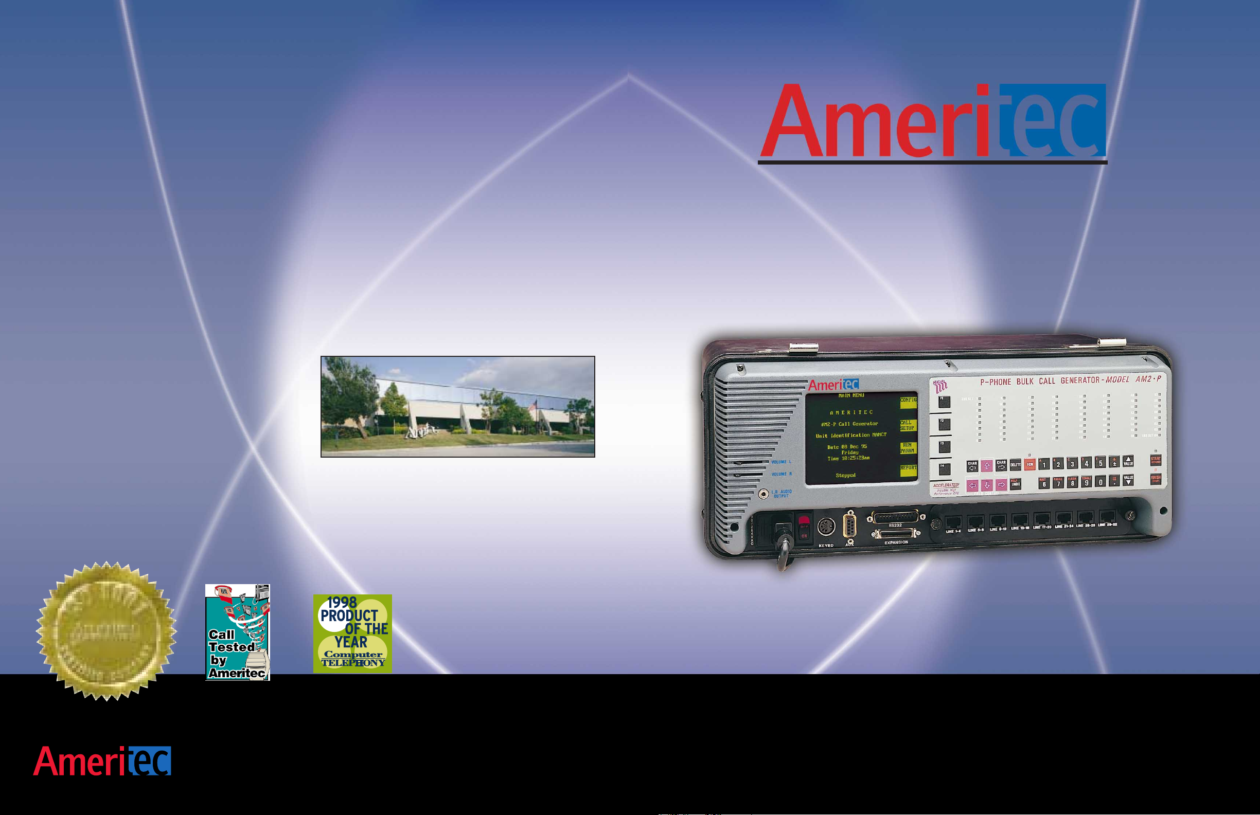
Portable Call Generators
AM2-A Analog AM2-D CAS
AM2-B ISDN BRI AM2-DX ISDN-PRI
AM2-P P-Phone (EBS) AM2-S7 SS7
AM2-Niagara¨
760 Arrow Grand Circle ¥ Covina CA 91722 ¥ +626 915 5441 ¥ www.ameritec.com
Page 2
T1/E1
PRI
TESTING
• Call Volume
• Delay to Answer
• Trunk & Station Simulation
• Prompt Response
• Simulate Callers
- Pulse, DTMF, MFR1
& MFR2 Signaling
- Secondary Tone
and digits
• Packet Loss (VoP)
• Round Trip Delay (VoP)
• ...(and more)
ANALOG/BASIC RATE/P-PHONE
AM2 Niagara w/FeatureCall
Graphical User Interface
1234\1234
1234
1234\1234
1234
Ameritec’s AM2 Niagara®family of products is
comprised of fully self-contained portable test
instruments designed to meet the rigid demands of
today’s telephony applications developer in both
laboratory and field applications. The AM2 Niagara,
simply put, makes telephone calls -- and lots of them!
Each AM2 Niagara unit allows interfacing to
different line types. One model interfaces to Analog
POTS lines, another to Analog P-Phones lines, others
to T1, E1, PRI, BRI, and SS7. The AM2 Niagara
allows users to develop a test environment with the
ability to test highly complex call scenarios.
•
AM2-A Analog Call Generator
provides physical interfaces for
64 analog line and 160 total lines
with the AM2E-A Expansion unit.
•
AM2-P P-Phone Call Generator
provides the physical interface
for 32 EBS lines.
•
AM2-B Basic Rate ISDN
Call Generator provides physical
interfaces for 32 BRI/BRA
ISDN U-Interface (2B1Q) lines.
•
AM2-D/De T1/E1 Digital Call
Generators provide physical interfaces
for four 1.544 Mbps T1 CAS trunks
or four 2.048 Mbps E1 CAS trunks.
•
AM2-DX/DXe Primary Rate
ISDN Call Generators provide physical
interfaces for four 1.544 Mbps T1
CCS trunks or four 2.048 Mbps
E1 CCS trunks.
•
AM2-S7/S7e SS7 Call Generators
provide physical interfaces for one to
four 1.544 Mbps T1 CCS trunks or
2.048 Mbps E1 CCS trunks and
supports up to eight SS7
signaling links.
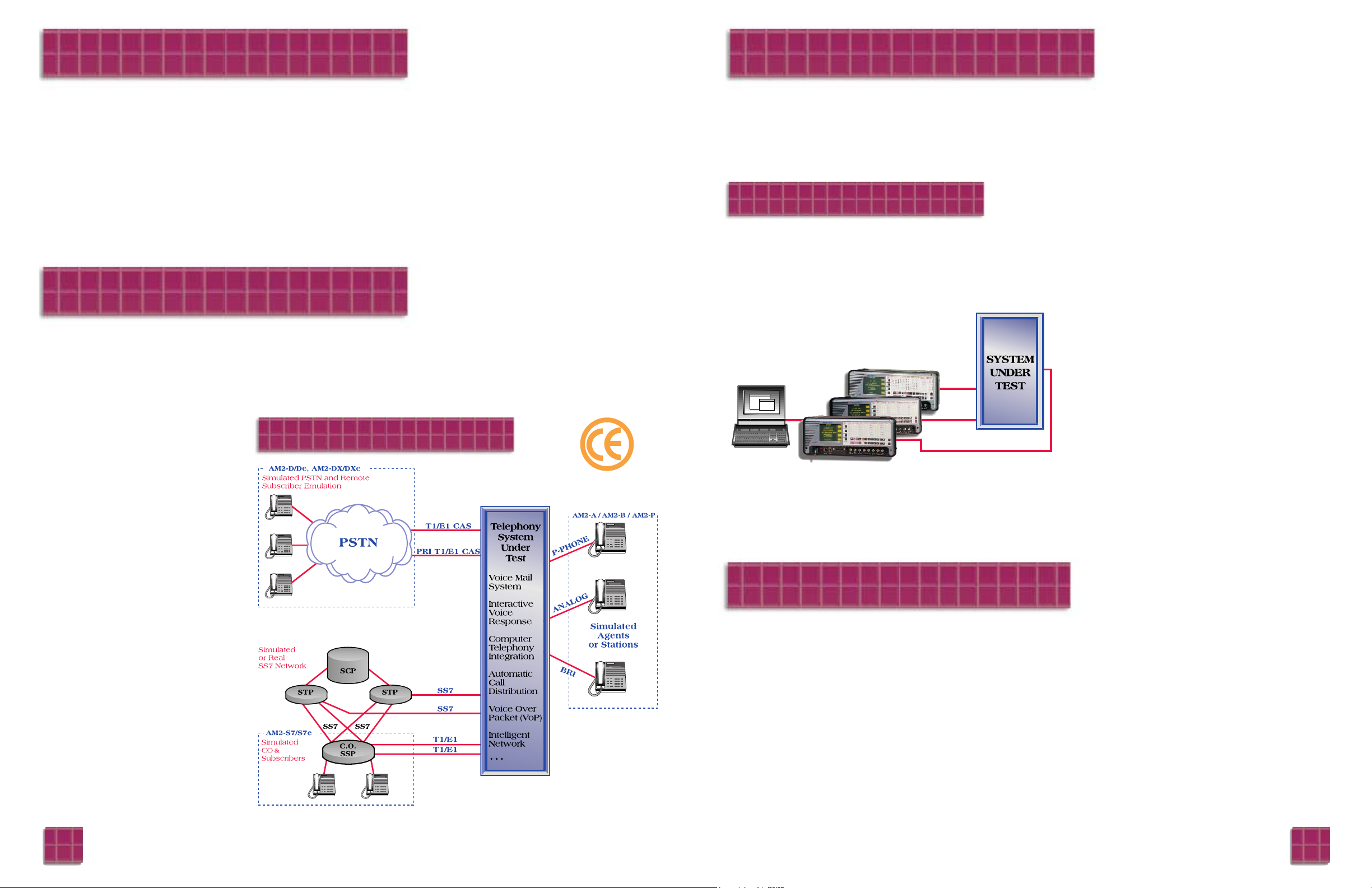
AM2 Niagara units are ideally suited for testing complex, interactive
applications under high call loads on dozens of lines simultaneously in the field
or a dedicated lab environment.
Applications that previously were too costly to test automatically can be easily
automated with the AM2 Niagara.
Such test applications include:
•
Central Office or PBX Switches and Networks
•
Voice Over Packet (VoFR, VoIP) Systems
•
Intelligent Network (IN) applications
•
Voice Mail systems
•
Computer Telephony Integration (CTI) systems and applications
•
Automatic Call Distribution (ACD) systems
•
Interactive Voice Response (IVR) systems
•
Paging systems
Each AM2 Niagara can simulate one to hundreds of telephony subscribers. The
actions of each simulated subscriber are independently controlled through
unique parameter fields defined in user programmed Call Scripts.
Scripts define calling patterns and can simulate practically any action a live
caller can perform. Scripts also simulate multiple subscribers allowing testing
of multiple-party calls such as conference calling.
•
Signaling: All interface specific signaling functions supported through
Call Scripts and user programmable signaling protocols.
•
Dialing: Multiple unlimited length dial strings, multiple dialing types,
including in-band end-to-end signaling (e.g. DTMF digits for interactive
applications).
•
Digit decoding: Decode in-band DTMF or MF digits.
•
Tone Send: Send pre-programmed single frequency tones.
•
Tone Receive: Detect any single frequency tone.
•
Path Verification: Comprehensive two-way verification of multiple party
voice and data path connections via in-band sequences, BERT patterns,
X.25 packet data, or packet drop detection (VoP).
•
Voice Replay: Optional feature allowing replay of pre-recorded audio
samples on demand.
•
ADSI: Optional feature permits the testing of caller ID functionality.
•
Delays: Event-to-Event delay measurements, round trip delays (VoP).
Testing Your Applications
Test configurations can, via Ameritec’s FeatureCall
GUI, control up to 32 AM2 Niagara’s via an Ethernet
®
TCP/IP LAN.
Through the use of user defined call scripts and line
protocols, users can tailor test scenarios to meet a
wide range of testing requirements. Whether the
testing demand is focused on development, production
testing, quality assurance or regression testing, the
AM2 Niagara family provides the flexibility to satisfy
your testing needs.
Introduction
Testing Applications
Models
Capabilities in Call Scripts include:
The AM2 Niagara has the flexibility to serve a wide range of telephony testing requirements including both
switch and network testing applications, in a captive lab or as a fully self-contained test tool. Whether your
application calls for a single interface, or for multiple physical interfaces, the AM2 Niagara family
provides a configuration that will meet or exceed your needs.
21
Page 3
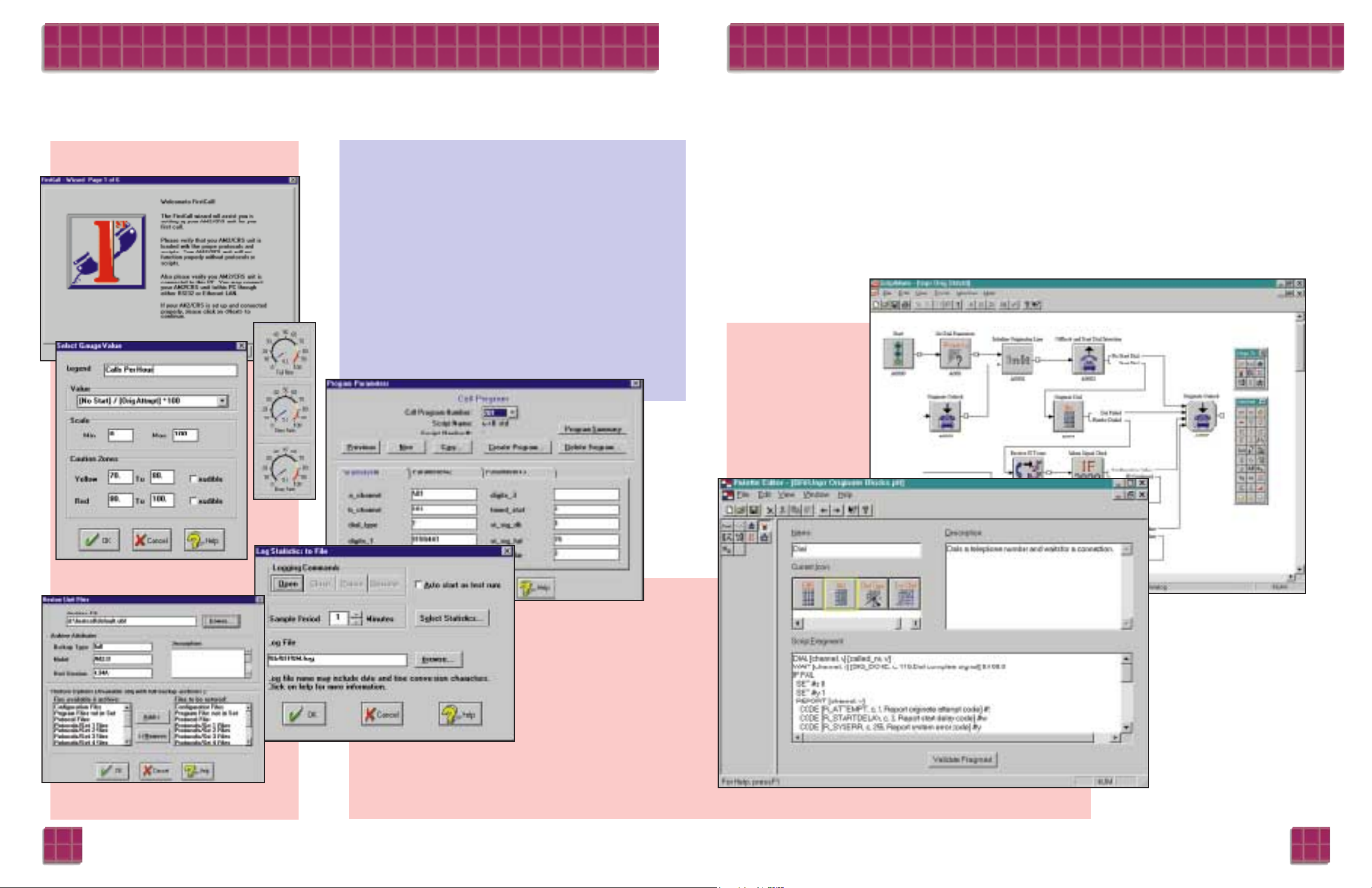
FeatureCall™ - Graphical User Interface
Each AM2 Niagara comes with FeatureCall, a Windows based Graphical User Interface (GUI) that provides
control and management, via a personal computer, of one or more Ameritec Call Generators via a TCP/IP LAN
or a single RS232 port. FeatureCall provides the user with simple, easy to use tools that allow you to:
• Create a system of 1 to 32 AM2 Niagara Call
Generators also (Crescendo®, and AM2S Squirt™)
• Create and start a test case in five easy steps using the
FirstCall™ Test Case Wizard
• Using Test Case™ create batteries of tests that can be
set to start on a schedule that you define days, weeks,
or months in advance
• Create traffic profiles using TrafGen™
• Automatically load test cases into your
AM2 Niagara from a test library that you build
using the backup and restore function of FeatureCall
• See your test case results as they run via a Gauge field
that allows you to define the areas of the test that are
critical for you to monitor
• Create reports the way you like them using the
Statistic Logging and Report Generation capability of
FeatureCall
Create a test case in 5
simple steps
Manage your test cases with a
test case repository
Create reports that verify
your test results
View the way the test
is running
Make changes to the
test case as it runs
Create or modify your
call flow diagram
interactively
View script detail
fragment whenever
you wish
ScriptMate™ - Graphical Test Script Builder
Testing complex telephony applications requires you to develop many test
cases. Limited programmability or learning a programming language used to be
your choices - until ScriptMate! ScriptMate is a graphical tool that allows you
to develop sophisticated test scripts by simply drawing the test sequence!
AM2 Niagara Call Generators offer you the ultimate in flexibility by providing
powerful built-in test case scripting capabilities. This level of flexibility is what
gives the AM2 Niagara its power. ScriptMate is a tool that unlocks this power
with an intuitive, easy-to-use, graphical test script generation method.
ScriptMate is a companion program to FeatureCall and allows you to easily
develop call test scripts by dragging, dropping and interconnecting simple icons
to create a graphical Call Flow Diagram. With a single click of the mouse, the
Call Flow Diagram is converted into a complete Script source file that can be
loaded into your
AM2 Niagara using
FeatureCall.
43
Page 4

Call Scripts &
Call Programs
Call Scripts are templates
defining the actions of a single
caller. The Call Script defines
calling patterns, voice path confirmation requirements and the
supplemental tones and digits used
in simple applications and complex
calling scenarios. A number of scripts
for common testing needs are provided
with each unit.
Using the Call Script as a template, call
variables (parameters) such as “dialed
number” are added to create a Call
Program. There is a separate Call
Program for each line or channel
in the unit. Call variables can be
changed by the user to build
new Call Programs, even with
the unit running tests. All Call
Programs are stored in
non-volatile memory.
User Defined Functionality
All AM2 Niagaras are furnished with front panel controls and FeatureCall, Ameritec’s Windows based
Graphical User Interface (GUI) that provides control for test applications with a single AM2 or multiple units
via an RS232 port or over a TCP/IP LAN. FeatureCall provides an easy method to configure units,
create tests parameters and run test cases.
Customizing Call Scripts & Protocols
The AM2 allows users to develop scripts and protocols to meet their specific
needs. Custom scripts and protocols may be developed by simply modifying
the ones supplied with the unit, or new ones may be developed from the ground
up using available tools.
Call Scripts are developed by using either ScriptMate, Ameritec’s Graphical
test script generator tool or in a standard Text Editor. Scripts can be automatically downloaded to a unit through FeatureCall’s Call Setup Script window.
Protocols can be developed or customized using Ameritec’s Protocol
Development Kit. The kit runs on a personal computer and consists of a
protocol development guide and an assembler/linker.
Automation Interface
As an alternative to the front panel control or FeatureCall, the AM2 provides
a control interface for users with proprietary test systems software. The communication is a command line format that allows easy integration of the AM2
into an automated test system.
Protocol Assignments
The AM2 uses Protocol State Tables to translate the call instructions from the
Call Program Test Set to a sequence of signaling events that are recognized by
the network. The AM2 can support multiple protocols running simultaneously
and the user has the ability to assign them to lines and channels as necessary.
Each AM2 is supplied with protocols that are standard for their model type.
Statistics & Error Messages
Statistics are automatically accumulated in the unit.
Reports include totals for each line/channel, the
number of errors recorded as well as totals for the
system. The amount of statistical information reported
is at the control of the user. Reports may be output to
a printer or computer.
The Real Time Error Log automatically records
error conditions occurring in the running Test Set.
Errors are reported on call setup, call completion and
other conditions defined by Protocol State Table and
Call Script. Each error record contains the Call
Program name, line or channel affected, time and date
of the error, the error type, and a short description of
the error. The report also contains the start and stop
times of the Test Set.
Call Program Test Sets
A Call Program Test Set consists of a collection of
Call Programs that have been assigned to various lines
or channels for convenient pre-programmed or
automated testing.
Call Scripts
(Template)
Call
Programs
Call
Instructions
Call
Signaling
Call
Variables
(Parameters)
Statistics & Error Messages
Multiple Call Programs =
Call Program Test Sets
Protocol Assignments
5 6
Page 5

Voice Channel Functions
Tone detectors and Circuit Switched Voice Functions
The AM2 Niagara product line consists of different
models providing physical interfaces for Analog
P-Phone, T1/E1 CAS, ISDN PRI/BRI and SS7.
Call Programs
Voice Path Confirmation
Digit Generators
Dialed digit strings are of unlimited length
Printouts and Reports - Call Statistics
Data is internally stored
General Characteristics
Voice Replay Option
This option provides up to 64 two second recorded
messages for AM2 Niagara Models AM2-A, AM2-B,
AM2-D, AM2-De and AM2-P
Line and channel path • 10 user selectable single tone signals to send
verification -- unique channel ID tones
Circuit Switched Voice • Encoding Scheme:
for Digital AM2 0: 1025 Hz 1: 1150 Hz 2 : 1275 Hz 3: 1400 Hz
Models): 4: 1525 Hz 5 : 1650 Hz 6: 1775 Hz 7: 1900 Hz
8: 2025 Hz 9 : 2150 Hz
• 64 user selectable single tone signals
Circuit Switched Data: • 511 and 2047 BERT pattern test for 56 kBps or
(Digital AM2 Models 64 kBps channels
only): • 511-bits pattern conforms to CCITT 0.153
• 2047-bits pattern conforms to CCITT 0.152
Packet Switched Data: • Up to 5 user selectable X.25 packets for
(AM2-DX/DXe and confirmation
AM2-B only)
Voice Over Packet Option
General Specifications: The general specifications
define the features and capabilities that are common to
all AM2 Niagara Models.
Call Program Sets: 4 per unit, stored in non-volatile memory
Call Programs: 480 per unit, memory resident (640 for
AM2-B)
Features: • FeatureCall Graphical User Interface
• Commonly used scripts supplied with unit
• Custom scripts created and downloaded from
FeatureCall
System Start Modes: • Synchronous
• Random
• Manual
Trouble Encounter Response: • Continue
• Call stop
• Unit stop on trouble
Detectors: • Tone detectors are based on Digital Signal
Processors (DSPs) 1 per channel/line
Call Progress Detectors: • One detector per line or B-channel
• Detects: dial tone, busy, reorder, ring,
ringback, supervision, wink
Path Confirmation • One receiver per line or B-channel
Receiver: • Frequency range: 10 to 2500 Hz
• Accuracy: 1%, ± 10 Hz
• Sensitivity: 0 dBm to -24 dBm
• Response Time: 12.5 ms
Signaling Tone • One receiver per channel
Decoders: • Detects signaling tones for SOCOTEL
(AM2-D/De Only) and ITU-T (CCITT) #5 signaling schemes
MF Receiver: • Decodes received MF digits DTMF, MFR1 MFR2
• Response time: under 40 ms
• Dynamic range: 35 dBm
Dial Pulse Generator: • Programmable dial speed: 1 pps to 999 pps
• Dial break: 1 to 99%
• Inter-digit time: 1 to 999 ms
Multitone • One digit generator per line
Digit Generators: • Dialing codes: MF R1, MF R2, DTMF
• Default level: -9 dBm
• Default frequencies: Nominal ± 0.005%
• Programmability: Each line individually
programmable for level 0 dBm to
-50 dBm in 1 dB steps for each frequency
component
• Programmable frequency range:
Up to 12.5% above or below nominal in
0.1% steps for each frequency component
Controls
Manual Reports: • Call statistics for each line or channel
• Totals for all lines and channels
Automatic Reports • Prints automatically on the hour or every
half or quarter hour
• Report categories are user selectable
Call Statistics for • Call attempt count
each originate line • Call completion count
or channel: • Delayed dial tone (AM2-A only)
• No dial tone count (AM2-B only)
• Delayed start signal count (Except AM2-A)
• No start signal count (Except AM2-A)
• No alert signal count
• No voice path or B-channel confirmation count
• Busy signal encountered count
• No answer signal count
• Ring time-out count (Except AM2-B,
AM2-DX/DXe)
• Average dial tone delay
• Average post dial delay
• Custom code report count (programmable
in test script)
Call Statistics for each • Attempted calls count
terminate line or • Completed calls count
channel: • Custom code report count (programmable
in test script)
For each packet • Call Attempts
switched originate • Completed Calls
channel • Average connect acknowledge delay
(ISDN-BRI and • Slow connect acknowledge delay
ISDN-PRI only): • No connect acknowledge
• Number of packets sent
• Number of packets re-sent
• Average packet delay
• Custom code report count (programmable
in test script)
For each packet • Attempted calls count
switched terminate • Completed calls count
channel • Custom code report count (programmable
(ISDN-BRI and in test script)
ISDN-PRI only):
Audio Monitor • Two volume controls adjust the stereo level of
Interface: the internal loudspeaker
User Interface: • FeatureCall Graphical User Interface
• Command line control via RS232C or Telnet,
(TCP/IP Ethernet)
RS232/V.24 Ports: • Two Serial Ports: Main / Auxiliary. Full duplex
on 3 wires. Provide GUI access, printer output,
remote control and chaining operations.
Ethernet: • 10 Base-T interface
• Telnet
• TCP/IP
• Configurable addressing via RS232 port: IP,
Subnet Mask, Gateway and Transmission Frame
Type
• IEEE 802.3 or Ethernet II packet format
• Maximum Transmission Unit (MTU) limit
1492 for IEEE 802.3, or 1500 for Ethernet II
• 48 bit Ethernet address
• Class 1 Logical Link Control (LLC)
• Address Resolution Protocol (ARP)
• Internet Control Message Protocol (ICMP)
• User Datagram Protocol (UDP)
PC Requirements • MS-DOS operating system 3.3 or
FeatureCall higher
(Customer provided): • Microsoft Windows operating system
version 3.x and/or Windows ‘95
• 486DX or higher microprocessor
• 4 MB of memory, 8 MB recommended
• Hard Disk space required for installation:
5 MB minimum
• One 3.5” high density disk drive
• SVGA or higher resolution monitor
• Windows compatible mouse
• RS232 19,200 Baud com:port
• Ethernet TCP/IP Packet Driver (optional)
Dimensions: • 16.8" Wide (730mm) x 7.2" High (185mm) x
11.5" Deep (295mm)
Power: • 90 to 264 VAC, 47 to 65 Hertz, 65 Watts
Weight: • 16.5 Pounds (7.5 Kilograms)
AM2 Niagara Unit Specifications
Voice Replay Option:
Adds VoP measurement capabilities to all models
except AM2-B, AM2-P
Voice Over Packet Option:
Real Time Error • Displayed or printed as they occur
Reports: • Details of the last 100 errors are stored
• Error reports include: type, the line(s) or
channel(s), time
• Error types recognized and reported:
• Slow dial tone (AM2-A only)
• No dial tone (AM2-A only)
• Slow start (Except AM2-A)
• No start (Except AM2-A)
• No alert tone
• Path or B-channel confirmation failed
• No answer signal
• Ring time-out (Except AM2-B and
AM2-DX/DXe)
• Busy
• Protocol cause values (ISDN-BRI,
ISDN-PRI & SS7 only)
• Custom code report count
(programmable in test script)
Display: • Flat panel high resolution electroluminescent
screen with bit-mapped graphics capability
characters 8 x 16 pixels
Display Format: • 40 characters by 16 lines
User Init: • Menu Driven
Keypad: • 29 keys including 4 soft, curser keys, function
keys, numeric keys, and unit start and
finish keys
Voice Path Confirmation: • Golden Voice™ signal designed to pass
through vocoder
Packet Drop Out Count: • Count lost packets for frame sizes of
5, 10, 15, 20, 30, 40 and 100ms
Measure Delays Through • Round Trip Delay
Systems: • One Way Delays
Measure Clipping of Voice: • Peak and average clipping of standard reference
with ± 10ms accuracy
7 8
Number of channels per option: • 64
Length of each phrase: • 2 seconds, repeated until a new phrase or quiet
is selected
Number of phrases: • 64 per option
(Voice Messages)
Phrase selection: • SENDVOX command in script
Voice output: • Selected voice signal is output on the channel
assigned in the Call Program
Output level: • Determined at the time of recording
Recording: • Created in a PC with a sound card and Ameritec
software
Required recording hardware: • Creative Labs Sound Blaster™ or equivalent,
16- bit audio card
• EPROM Programmer
• PC running DOS 3.x or higher
All Models Available in
CE Compatible Versions
Page 6

The AM2-A Analog Call Generator provides line
interfaces for 64 analog lines and 160 total lines with
the AM2E-A Expansion Unit.
System
FSK
Expanded System Specifications for ADSI Option
Provides Analog Display Service Interface
(ADSI)/Caller ID test functionality on AM2 Niagara
Model AM2-A.
Dual Tone Alert Signal Detection
Capacity: • 64 Analog lines:
Signaling Protocols: • Bellcore TR-NWT-000030, or
• British Telecom (BT) SIN 227 and SIN 242,
Cable Television Association (CTA)
TW/P&E/312
US Signaling Protocols: Low tone frequency: 2130 Hz ± 0.5%
High tone frequency: 2750 Hz ± 0.5%
Receive signal level: -14 dBm to -32 dBm per
tone, off hook
Signal reject level: -45 dBm
Twist: Up to 6 dB
Unwanted signals: Less than -7 dBm ASL
near end of speech
Duration: 75 to 85 ms
Speech present: Yes
Non-US Signaling Protocols: Low tone frequency: 2130 Hz ± 1.1%
High tone frequency: 2750 Hz ± 1.1%
Receive signal level: -2 dBV to -40 dBV per
tone, off hook
Signal reject level: -45 dBm
Twist: Up to 7 dB
Unwanted signals: Less than -20 dBm 300 to
3400 Hz
Duration: 88 to 110 ms
Speech present: No
US Signaling Mark frequency (logic 1): 1200 Hz ± 1%
Protocols: Space frequency (logic 0): 2200 Hz ± 1%
Received signal level mark: -12 dBm to -32 dBm
Received signal level space: -12 dBm to -36 dBm
Twist: Up to 10 dB
Unwanted signals: Less than -25 dBm 200 to
3200 Hz
Transmission rate: 1200 Baud ± 1%
Word format: 1 start bit = 0, 8-bit word
(LSB first), 1 stop bit = 1
Non-US Signaling Mark frequency (logic 1): 1300 Hz ± 1.5%
Protocols: Space frequency (logic 0): 2100 Hz ± 1.5%
Received signal level mark: -8 dBV to -40 dBV
Received signal level space: -8 dBV to -40 dBV
Twist: Up to 6 dB
Unwanted signals: Less than -20 dBm 300 to
3400 Hz
Transmission rate: 1200 Baud ± 1%
Word format: 1 start bit = 0, 8-bit word
(LSB first), 1 stop bit = 1
AM2-A and AM2E-A Specifications:
ADSI Option:
The AM2-P Analog Call Generator provides line
interfaces for 16 to 64 analog lines.
System
Signaling Channel
AM2-P Specifications:
Capacity: • 32 P-Phone (EBS) originating/terminating lines
Each line emulates up to:
• 1 primary set and 3 add-ons
• 1 extension set and 3 add-ons
Call Volume: • 7,500 confirmed calls per hour
Line Types: • Lines compatible with NIS S106-1
• DTMF, MF R1 and MF R2 dialing
• 900 ohm impedance
• Simulated sets are not loop powered
9
10
Capacity: • AM2-A 64 analog lines
AM2E-A 96 analog lines
Call Volume: • AM2-A typically 16,000 confirmed calls per
hour (DTMF dialing, tone ID confirmation, 64
paired lines)
• With AM2E-A expansion unit 40,000 confirmed
calls per hour (80 paired lines)
Line Interface • Loop Start, 2-wire (optional Ground Start)
Options: • Pulse, DTMF, MF R1 & MF R2 dialing
• 900 ohm impedance (optional 600 ohm
impedance)
• Optional 50Hz, 12Hz and 16kHz Meter Pulse
Detection
Front Panel Indicators: • 64 LEDs, one per line
• Line Status Display:
Dark: Idle line
Green: Originate line off hook
Yellow: Terminate line off hook
Red: Line error
Message Format: • Amplitude Shift Keying (ASK), 16 Bit envelope
Carrier Frequency: • Transmit : 8,000Hz ±200ppm
Level: 1.3 volts peak-to-peak,
± 0.2 volts
• Receive: 8,000Hz ±200ppm
Level: 1.5 volts peak-to-peak
maximum
0.9 volts peak-to-peak
minimum
Bit Rate: • 1,000 bits per second ±2% half-duplex
Page 7

System Signaling Systems
AM2-D System
The AM2-B Basic Rate ISDN FeatureCall Generator
provides the line interfaces for 32 BRI/BRA-ISDN
U-Interface (2B1Q) lines.
The AM2-D Digital Call Generator provides the inter-
face for one to four 1.544 Mbps T1 or one to four
2.048 Mbps E1 trunks (AM2-De).
AM2-B Specifications: AM2-D and AM2-De Specifications:
Capacity: • 32 BRI/BRA ISDN U-Interface lines
• Each U-Interface port emulates 1 to 8 TEs
Call Volume: • Typically 48,000 confirmed calls per hour
(depending on switch performance)(32Lines)
• X.25 Packets per second: Up to 2,024 packets
per second
Front Panel Indicators: • B-channel: 64 LEDs, one per B-channel
• B-channel Status Displayed:
Dark: Idle line
Green: Originate call
Yellow: Terminate call
Red: Error
• D-channel: 32 LEDs, one per D-channel
Dark: Idle line
Green: Call in progress
Red: Error
Trace Port: • One RJ-45 Trace/Insert Port
• 4-wire, ISDN-S/T Interface provides access to
any U-Interface line
• Switch selectable: insert or trace
Test Loops: • Meets transmission requirements for Loop #1
through Loop #15 of ANSI’s 15 telephone plant
test loops
Warm and Cold Starts: • Warm Start: 300 ms synchronization
• Cold Start: 15 second synchronization
AM2-De System
Indicators and Alarms
11 12
Layer 1: • 2B1Q, ANSI T1.601-1992 ISDN Basic Access
Interface for use on metallic loops for
application on the network side of the NT
• Data Transmission: Full duplex at a rate of
160 kBps
Layer 2: • Q.921/LAPD and LAPB (X.25) Layer 3: Q.931
and equivalent standards
• Up to 8 different L3 protocols may be
downloaded to unit
• Permits L3 protocol assignment for each
U-Interface
• Various international protocols supported
• Additional protocols can created and
downloaded from Workstation or PC
Packet Data: • X.31 Case A and Case B
• BPS: B-channel X.25 packet data
• DPS: D-channel X.25 packet data
Circuit Switched: • CSD: Circuit switched data (BERT)
• CSV: Circuit switched voice
Supported • National ISDN (N1)-1
Standard: • National ISDN (N1)-2
• Euro-ISDN
• #5ESS Custom
• EKTS
• ETSI
Capacity: • AM2-D:
• Four 1.544 Mbps PCM 24 channel T1
CAS trunks
• Menu selectable D3/D4 Framing or ESF
• Up to 96 simultaneous calls (4 spans)
• All channels can originate or terminate calls
• PCM timing may be sourced internally or from
one of the four trunks within the group
Interface Options: • Bantam 100 ohm balanced input connectors
• Bantam 120 ohm balanced input connectors
Call Volume: • AM2-D: 48,000 confirmed calls per hour (4 spans)
Front Panel Indicators: • One per channel or time slot
• Channel Status Display:
Dark: Idle line
Green: Originate call
Yellow: Terminate call
Red: Error
• Layer 1 Indicators:
PCM Sync (green: normal, red: out-of-sync)
Frame Error, CRC Error, Slip (dark: normal,
red: error)
• AM2-D Alarm Indicator:
Dark: Normal
Red: Indicates red, yellow or blue alarm
received
• AM2-De:
Provides status of TS16 (dark: normal, yellow:
Distant multiframe alarm, red: signal all ones
alarm
Capacity: • AM2-De:
• Four 2.048 Mbps PCM 32 channel E1
CAS trunks
• Menu selectable CRC-4
• Up to 120 simultaneous calls (4 Spans)
• All channels can originate or terminate calls
• PCM timing may be sourced internally or from
one of the four trunks within the group
Interface Options: • Triple Banana 120 ohm, balanced input connectors
• BNC 75 ohm, unbalanced input connectors
• Siemens 1, 6/5, 6 (DIN 47295), 75 ohm,
unbalanced input connector
• Bantam 120 ohm balanced input connectors
Call Volume: • AM2-D: 48,000 confirmed calls per hour (4 spans)
Page 8

AM2-S7 System
The AM2-S7 Call Generator provides the interface
for four 1.544 Mbps CCS T1 or one to four 2.048
Mbps CCS E1 trunks (AM2-S7e).
AM2-S7 and AM2-S7e Specifications
Signaling System
The AM2-DX Primary Rate ISDN Call Generator
provides the interface for one to four 1.544 Mbps CCS
T1 or one to four 2.048 Mbps CCS E1 trunks
(AM2-DXe).
AM2-DX and AM2-DXe Specifications
AM2-DXe System
AM2-DX System
Signaling Systems
AM2-S7e System
14
13
Indicators and Alarms
Front Panel Indicators: • One per channel or time slot
• Channel Status Display:
Dark: Idle line
Green: Originate call
Yellow: Terminate call
Red: Error
• Layer 1 Indicators:
PCM Sync (Green: normal, red: out-of-sync)
Frame Error, CRC Error, Slip (dark: normal,
red: error)
• AM2-DX Alarm Indicator:
Dark: Normal
Red: Indicates red, yellow or blue alarm
received
• AM2-DXe: Provides status of TS16 (dark:
normal, yellow: distant multiframe alarm,
red: signal all ones alarm
Capacity: • Signaling links:
• Eight 56/64K SS7 Signaling Links per unit.
Modular Interface options include:
Two x T1 1.544 Mbps (AM2-S7)
Two x E1 2.048 Mbps (AM2-S7e)
Eight x V.35 56/64 kBps
Eight x DSOA 56 kBps
• Fully associated links using time slots in the
voice/data circuits are supported
• AM2-S7 Voice & Data Circuits:
• Four 1.544 Mbps PCM 24 channel
T1 CCS trunks
• AMI and B8Zs Line Coding
• D4 or ESF framing
• AM2-S7e Voice & Data Circuits:
• Four 2.048 Mbps PCM-30/PCM-31
E1 CCS trunks
• HDB3 line coding
• CRC4 framing
AM2-S7 Interface • 1.544 Mbps Signaling Interface option with
Option: 8 SS7 signaling links. Bantam 100 ohm,
balanced input
• 1.544 Mbps Signaling Interface option with
8 SS7 signaling links. Bantam 120 ohm,
balanced input
• V.35 Signaling Interface Option with 8 SS7
signaling links on 8 V.35 Interfaces, T1,
100 ohm, unbalanced input
• V.35 Signaling Interface Option with 8 SS7
signaling links on 8 V.35 Interfaces, T1,
120 ohm, unbalanced input
• DSOA Signaling Interface Option with 8 SS7
signaling links on 8 DSOA Interface. T1,
100 ohm, balanced input
• DSOA Signaling Interface Option with 8 SS7
signaling links on 8 DSOA Interface. T1,
120 ohm, balanced input
Call Volume: • AM2-S7: 48,000 confirmed calls per hour
(4 spans)
Signaling Protocols • Bellcore Q.702 at level 1
AM2-S7 • Bellcore Q.703 at level 2
• Bellcore Q.704 at level 3
• Bellcore Q.761 to Q.766 ISUP signaling
Signaling Systems
Capacity: • AM2-S7e Voice & Data Circuits:
• Four 2.048 Mbps PCM-30/PCM-31
E1 CCS trunks
• HDB3 line coding
• CRC4 framing
• Modular interface options:
• Balanced 100 ohm or 120 ohm, Bantam
• Unbalanced 75 ohm, BNC
AM2-S7e Interface • 2.048 Mbps Signaling Interface option with
Option: 8 SS7 signaling links. BNC 75 ohm, balanced
input
• V.35 Signaling Interface option with
8 SS7 signaling links on 8 V.35 Interface.
E1, 75 ohm, balanced input
Call Volume: • AM2S-S7e: 60,000 confirmed calls per hour
(4 spans)
Signaling Protocols • VN4
AM2-S7e: • CCITT Q.702 at level 1
• CCITT Q.703 at level 2
• CCITT Q.704 at level 3
• CCITT Q.761 to Q.766 ISUP signaling
• BTNR 167
• Regional TUP varieties
Indicators and Alarms
Front Panel Indicators: • One per channel or time slot
• Channel Status Display:
Dark: Idle line
Green: Originate call
Yellow: Terminate call
Red: Error
• Layer 1 Indicators: PCM Sync (green: normal,
red: out-of-sync) Frame Error, CRC Error, Slip
(dark: normal, red: Error)
• AM2-S7 Alarm Indicator:
Dark: Normal
Red: Indicates red, yellow or blue alarm
received
• AM2-S7e: Provides status of TS16 (dark:
normal, yellow: distant multiframe alarm,
red: Signal all ones alarm
Capacity: • AM2-DX:
• Four 1.544 Mbps PCM 24 channel
T1 CCS trunks
• 24 timeslots (23B+D) per trunk
• AM1 and B8ZS Line Coding
• Menu selectable D3/D4 Framing or
ESF formats
Interface Options: • Bantam 100 ohm balanced input connectors
• Bantam 120 ohm balanced input connectors
Call Volume: • AM2-DX: 48,000 confirmed calls per hour
(4 spans)
Capacity: • AM2-DXe:
• One to four 2.048 Mbps PCM 32 channel
E1 CCS trunks
• 32 timeslots (30B+D) per trunk
• HDB3 Framing
• Menu selectable CRC-4 on/off
Interface Options: • Triple banana 120 ohm, balanced input connectors
• BNC 75 ohm, unbalanced input connectors
• Siemens 1, 6/5, 6 (DIN 47295), 75 ohm,
unbalanced input connector
• Bantam 120 ohm balanced input connectors
Call Volume: • AM2-DXe: 60,000 confirmed calls per hour
(4 spans)
Signaling System Layer 1: • Complies with ANSI T1.408
• Complies with ITU-T (CCITT) 1.412 and 1.431
Signaling System Layer 2: • Q.921/LAPD and LAPB (X.25) Signaling
Signaling System Layer 3: • Q.931 and equivalent standards
• Up to 8 different L3 protocols may be down
loaded to unit
• Menu selection of L3 protocol for each B- and
D-channel
• D- or signaling channel may be assigned to any
physical time slot
• Various international protocols supported
• Additional protocols can be created and
downloaded from Workstation or PC
Packet Data: • X.31 Case A and Case B
• BPS: B-channel X.25 packet data
• DPS: D-channel X.25 packet data
Circuit Switched: CSD: • Circuit switched data (BERT)
• CSV: Circuit switched voice
 Loading...