

Page 1
Page 2

Before Use
● The size and appearance of this monitor may be changed for improvement without
notice.
● This user manual contains proprietary information that is protected by copyright.
All rights are reserved. No part of this user manual may be reproduced, photocopied,
transcribed, translated or transmitted in whatsoever from without the prior permission
of the manufacturer.
● Damage caused by using the unauthorized components or disregard of the information
and cautions in this user manual is not covered by the warranty service.
● If you have problem with your monitor, please check TroubleShooting in this user
manual before asking for help service center.
● The information in this user manual is subject to change without notice.
● If you let display the static images on the LCD monitor for prolonged time, the LCD
monitor may show you the screen images retention. It is not a continuous condition
and will fade away in a period time. The Image retention is a condition that may occur
on all LCD monitors.
E
nglish
● The LCD consists of about 5 million pixels. One pixel includes 3 dots and some of dots
could be seen bright and dark compared to other dots. Please, note that it may occur
on all LCD monitors and it is not a product inferiority.
Page 3

E
nglish
CE Conformity Notice
The Product herewith complies with requirements of the Low Voltage Directive
73/23/EEC and the EMC Directive 89/336/EEC and carries the ‘CE’ mark accordingly.
Confirms to the following hamonized European standards have been applied:
EMC : EN 55022 Class B : 1998
EN 55024 : (EN 61000-4-2 : 1995, A1 : 1998, EN61000-4-3 : 1996, EN 61000-4-4:
1995, EN61000-4-5 : 1995, EN61000-4-4 : 1996, EN61000-4-8 : 1993 and
EN61000-4-11 : 1994)
EN61000-3-3 : 1995, A1 : 98, A2 : 98
EN61000-3-3 : 1995
FCC Compliance Statement
This device complies with Part 15 of the FCC Rules. Operation is subject to the following
two conditions : (1) this device may not cause harmful interference, and (2) this device must
accept any interference received including interference that may cause undesired
operation.
INFORMATION TO THE USER
This equipment has been tested and found to comply with the limits for a Class B digital
device pursuant to Part 15 of the FCC Rules. These limits are designed to provide
resonable protection against harmful interference in a residential installation.
This equipment generates, uses and can radiate radio frequency energy and if not installed
and used in accordance with the instructions, may cause harmful interference to radio
communication. However, there is no guarantee that interference will not occur in a
particular installation. If this equipment does cause harmful interference to radio or
television reception, which can be determined by turning the equipment off and on, the user
is encouraged to try to correct the interference by one or more of the following measures:
- Reorient or relocate the receiving antenna.
- Increase the separation between the equipment an receiver.
- Connect the equipment into an outlet in a circuit different from that to which the receiver is
connected.
- consult the dealer or an experienced radio / TV technician for help.
WARNING
Changes or modifications not expressly approved by the manufacturer could void the use’s
authority to operate the equipment.
Page 4
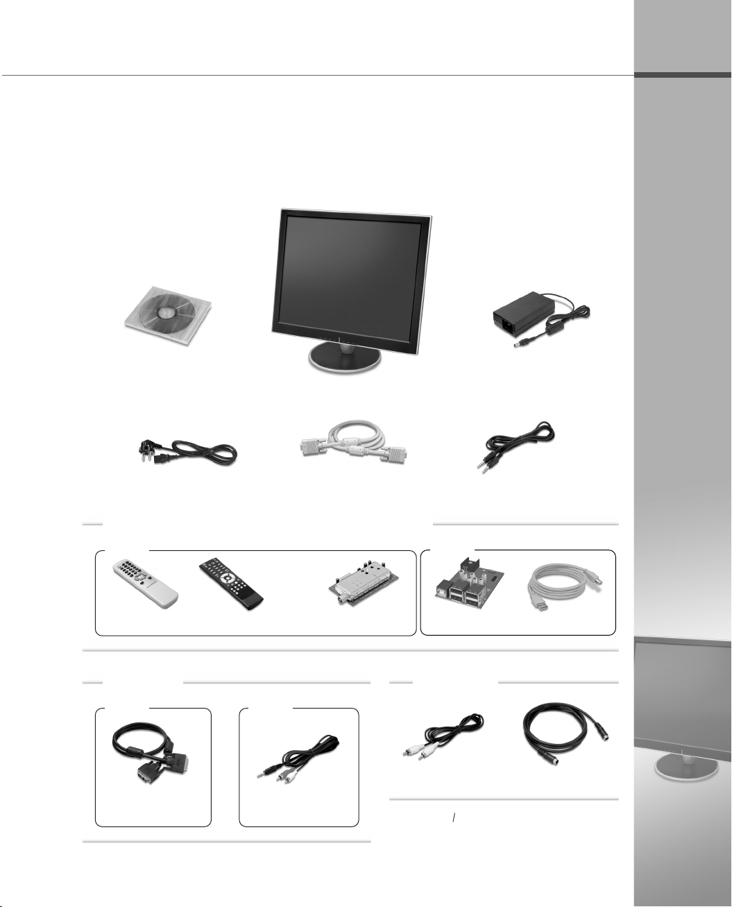
Unpacking
After opening the box, make sure the following items are provided with the monitor.
If you find that any of these items is missing or appears damaged, contact your
dealer immediately.
Monitor Driver
User Manual
Power Cord
Monitor
VGA Signal Cable
DC Adapter
Audio Cable
Optional (Simultaneous Selection is not possible)
TV
USB
E
nglish
Remote Control
Optional
DVI
DVI(Digital Video
Interface) Cable
Remote Control(TTX)
VIDEO
Audio(RCA) Cable
TV Tuner(included)
Video(RCA) Cable
*
The actua monitor and accessories may
appear differently from those shown on
the above figure.
USB 4 Port
Unbundled
USB Cable
S-Video Cable
Page 5
Instructions for Safety
E
nglish
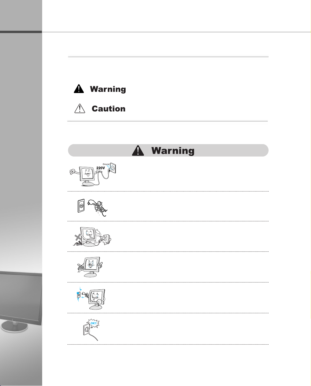
▶ Matters that demand special attention are divided into ‘Warning’ and
‘Caution’, and are detailed a follows.
In case of the possibility that a serious injury or death
may occur during a violation of the instructions.
In case of the possibility that a slight injury or product
damage may occur during a violation of the instructions.
● Don’t plug the power adapter into a non-grounding
power outlet.
● Never touch the power plug with wet hands.
An electric shock accident may occur.
●
Don’t plug with other electrical cords into one power outlet.
An electric shock or fire accident may occur.
● Only use the adapter provided with the monitor.
An electric shock or fire accident may occur.
● Don’t use a power cord or plug that is frayed or damaged.
An electric shock or ignition may be caused.
● Insert the plug completely so that the power supply unit
can be connected tightly.
Unsafe power connection may cause a fire.
Page 6
E
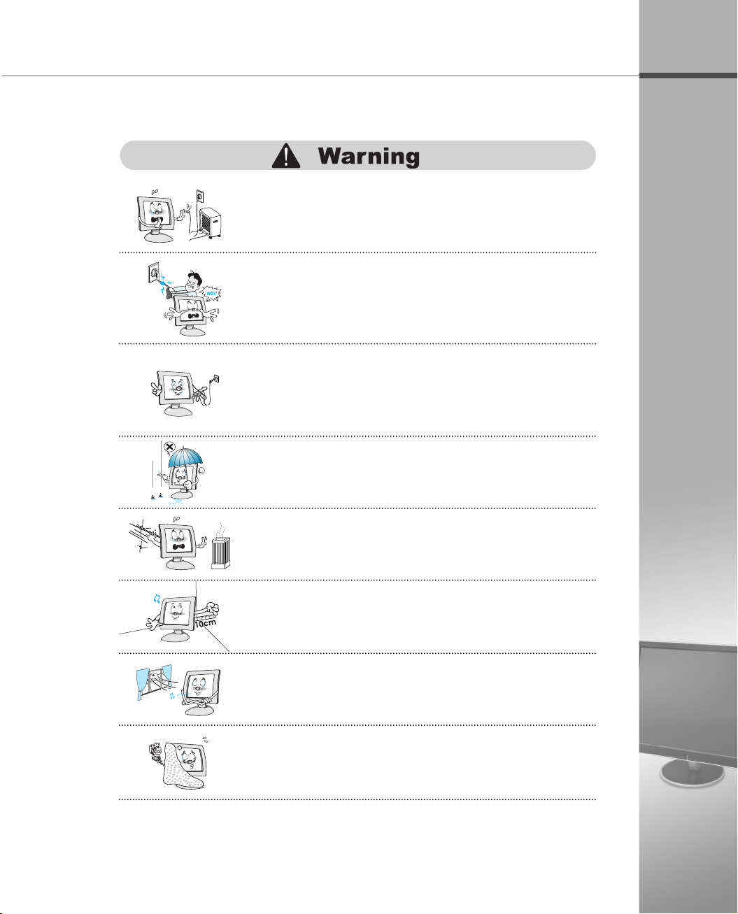
● Keep the power cord from proximity to a heating instrument.
The covering material of the cord may melt, causing a fire or
electric shock.
● Grasp the power plug at the base to remove it from the
wall, and pull firmly but gently.
If you yank at the cord, the wire may be broken, causing
ignition or heat generation.
● Pull the power cord out when the monitor is not used for
a long time, or while you are away.
A dust covering may cause an electric shock, electric leakage,
or fire by heat generation, ignition, and insulation degradation.
● Select a cool, dry area and protect your monitor from
extremes in temperature, humidity, dust and smoke.
Accidents of electric shock, fire or failure may occur.
● Avoid direct sunlight or any other source of heat such
as a fireplace.
A fire or electric shock accident may be caused.
nglish
● Place the monitor at a proper distance (over 10 cm)
away from the wall for sufficient ventilation.
A fire may be caused due to an increase in internal temperature.
● Place the monitor in a well-ventilated room.
A fire may be caused due to an increase in internal temperature.
● Note that air-flow holes must not be blocked such as a
table cloth or curtain.
A fire may be caused due to an increase in internal temperature.
Page 7
E
nglish
● Don’t block or obstruct the air-flow holes of the monitor.
A fire or damage of the monitor may be caused due to an
increase in internal temperature.
● Don’t spill liquids such as chemicals, water on the monitor.
A fire or electric shock accident may be caused.
● Never disassemble and repair the monitor but trained
repair engineers.
A fire or electric shock accident may be caused. If you need the
repair and adjustment, please contact the appropriate sales
agency or customer counsel window for check-ups.
● Don’t insert metals (such as coins, hair pins or ironware)
or flammable items (such as paper or matches) into the
monitor.
A fire or electric shock accident may be caused.
● Stop using in case of smoke or abnormal odors.
Immediately turn off the power and pull out the power
cord from the wall and then contact the service center.
Continuity of use in such a state may cause a fire or electric
shock.
● Don’t spray any liquids directly onto the monitor.
An electric shock or fire accident may occur.
● Clean the LCD panel with a soft material such as cotton
cloth after removing the power cord from the monitor.
A fire or electric shock accident may be caused.
Page 8
● Place the monitor on a stable and secure surface.
Fall or displacement of the monitor may cause an injury.
● Turn off the monitor and disconnect all cables from the
monitor before moving the monitor.
● Be careful with the shock when moving the monitor.
● Don’t scratch or jolt the monitor surface.
Damage or failure of the panel may be caused.
● Take hold of the monitor with both hands setting the panel
forward.
If the monitor is dropped, contact the service center to check it
for a susceptibility to fire or electric shock.
E
nglish
● Often take a rest to protect your eyes when you work
for a long time.
● Don’t press upon the panel or scratch the surface with
your hands or sharp item such as a nail, pens.
Damage or failure of the panel may be caused.
● The fluorescent light of the monitor contains a mercury
which could be exploded. Don’t discard or bury the
monitor without permission of the law concerned.
Page 9

CONTENTS
E
nglish
Installing the Monitor
1.1 Features …………………………………………………………………… 1-1
1.2 Installing the Support
Installing the Support
1.3 Monitor Overview
Front Side
Rear Side
1.4 Connecting the Peripheral Devices
…………………………………………………………………… 1-4
…………………………………………………………………… 1-4
…………………………………………………… 1-2
……………………………………………………… 1-2
………………………………………………………… 1-3
………………………………… 1-5
Installing the Monitor Driver
2.1 Installing the Monitor Driver Under Windows…………………… 1-9
Windows XP
2.2 Installing the Monitor Driver Under Linux
…………………………………………………………………………… 1-10
Linux
Adjusting the OSD
………………………………………………………………… 1-9
………………………… 1-10
(On Screen Display)
Menu
3.1 Selecting and Adjusting the OSD(On Screen Display) Menu
………………………………………………………………………………… 1-11
Selecting and Adjusting the OSD Menu
3.2 OSD(On Screen Display) Menu Functions
OSD Main Menu
OSD Sub Menu
CHANNEL MENU OSD (PAL/SECAM)
V-CHIP OSD
Punction for Teletext
…………………………………………………………… 1-12
…………………………………………………………… 1-12
………………………………………………………………… 1-20
……………………………………………………… 1-23
……………………………… 1-11
……………………… 1-12
……………………………… 1-16
Troubleshooting/Specification
A.1 Troubleshooting ………………………………………………………… A-1
A.2 Specification
……………………………………………………………… A-2
Page 10

1.1 Features
Adopt the 19.0” TFT LCD Narrow Bezel Panel
Adopt the 19.0” LCD(Liquid Crystal Display) narrow bezel panel which allows you
efficient use in a small space due to the slim design with wide screen.
AUDIO
It gives user an amplified stereo sound through internally installed speakers (2 W).
Support DVI (Digital Video Interface) (Optional)
High quality screen through direct digital signal from the computer.
Support the USB Ports (Optional)
It can be embedded to use the USB without an external Hub.
Enable to watch TV (Optional)
Enable to watch TV after connecting antenna cable.
Installing the Monitor
1-1
Page 11
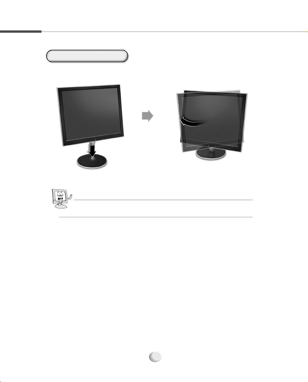
1.2 Installing the Support
Installing the Support
For safe use of the LCD monitor, it is necessary to fix the base. Install the base as shown in
the figure below.
CCaauuttiioonn
Be careful not to damage the LCD panel when installing the base.
1-2
Page 12

1.3 Monitor Overview
This section identifies the name of each component of the monitor and briefly
describes the function of each component.
Front Side
TFT LCD Display
Displays the current
contents of the
display.
SELECT Button
Selects the OSD
menu item and the
submenu item to be
adjusted in the OSD
menu window and
save the modified value at any
selected item. (If you press
continuously every two times, the
input source will be switched.)
MENU Button
Displays or Exits the OSD menu
window.
DOWN Button
Moves to the down menu item in the OSD menu
window.
UP Button
Moves to the up menu item in the OSD menu window.
appropriate condition to present mode.
This does not function when DIGITAL
Decreases the value of the
selected item. (Decreases the
volume without pressing the
Increases the value of the
selected item. (Increases the
volume without pressing the
POWER Button
Turns the monitor on
When you press this button, it is
automatically adjusted to the most
VIDEO CARD(DVI Card) is used.
(It is adjusted automatically)
Installing the Monitor
LEFT Button
MENU Button.)
RIGHT Button
MENU Button.)
and off.
AUTO Button
NNoottee
When watching the TV after connected TV tuner(Optional), use the
UP/DOWN Button without pressing the MENU Button to select TV
Channel.
1-3
Page 13

Rear Side
ANALOG Connector
Connects the VGA signal
cable to the VGA connector on
the computer.
DC-IN
Connects the DC
adapter to input the
power.
AUDIO IN
Connects the
audio cable to
the LINE OUT jack
on the computer or
the stereo jack on
the camcorder/VTR.
AUDIO OUT
Connects a set of
headphones or
external speakers.
TV Tuner (Optional)
Connects the TV antenna
cable.
USB DOWN 4 Port
(Optional)
Connects USB devices.
USB UP Port (Optional)
Connects the USB cable to the USB
connector on the computer.
VIDEO Jack (Optional)
Connects the video cable to the VIDEO jack on the
camcorder or VTR.
DVI Connector (DIGITAL) (Optional)
Connects the DVI cable to the DVI connector
on the computer.
NNoottee
▶ Self Diagnostics (ANALOG)
If the signal cable is improperly connected between the monitor
and the computer, the Self Diagnostics ANALOG NO SIGNAL
message appears on the monitor.
▶ Self Diagnostics (DIGITAL)(Optional)
If the signal cable is improperly connected between the monitor
and the computer, the Self Diagnostics DIGITAL NO SIGNAL
message appears on the monitor.
▶ To enjoy the sound with your monitor, at first you must connect the audio cable to AUDIO
IN jack on the monitor and LINE OUT jack on the computer, and then connect a set of
headphones or external speakers.
S-VIDEO Connector (Optional)
Connects the s-video cable to the S-VIDEO connector on the
camcorder or VTR.
1-4
Page 14

1.4 Connecting the Peripheral Devices
Turn off the monitor, computer and other peripheral devices before connecting the
monitor and peripheral devices.
Connecting the power
1
Plug into the power outlet at 220V or 110V. (The voltage is set utomatically.)
DC Adapter
Power Cord
Connecting the computer
2
Connect the VGA cable to the Analog connector or the DVI cable to the DVI connector
on the computer.
DC-IN Jack
Installing the Monitor
Connecting the Analog Connector
Analog Connector
VGA Cable
1-5
Analog Connector
Page 15

Connecting the DVI Connector(Optional)
DVI Connector
DVI Connector
DVI Cable
Connecting Audio Devices
3
Connect the audio cable to the AUDIO IN on the monitor and the LINE OUT on the computer
or connect the audio cable (RCA) cable to the AUDIO IN on the monitor and the stereo on the
camcorder/TV and connect a set of headphones or external speakers to the AUDIO OUT.
Set of
AUDIO OUT
headphones
or
Camcorder
Stereo
AUDIO IN
AUDIO(RCA) Cable
External Speakers
LINE OUT
AUDIO Cable
1-6
Page 16

Connecting the Camcorder(Optional)
4
Connect the S-VIDEO connector or VIDEO connector.
S-VIDEO Connector
VIDEO Connector (RCA Type)
Installing the Monitor
Camcorder
S-VIDEO
Connector
VTR
Camcorder
Connecting the TV Antenna(Optional)
5
VIDEO
Connector
VTR
TV Tuner (Optional)
TV Antenna Cable
1-7
Page 17

Connecting USB Devices (Optional)
6
At first, connect the USB cable to the USB UP port on the monitor and USB connector
on the computer and then, connect USB devices to the USB DOWN port on the
monitor.
USB DOWN Port
USB Connector
USB UP Port
USB Cable
USB Keyboard
USB CCD
or
or
Camera
USB Mouse
1-8
Page 18

2.1
1
2
3
4
Installing the Monitor Driver Under Windows
Insert the monitor driver installation CD into the CD-ROM drive.
To install the driver, select the relevant model in the Install the Driver window,
which is displayed automatically .
To use the monitor as a DVI, by connecting a computer that supports DVI, select
19.0 DIGITAL MONITOR.
If the program doesn’t run automatically, go to the drive containing the driver
installation CD and run the setup.exe file.
Installing the Monitor Driver
1-9
Page 19

2.2
Linux
You’d make xf86config file to run X-Window. Your monitor is surely and easily
1
configured with this file. This file will be made as running xf86config.
Press Enter in the first and second window after running xf86config file.
2
In third window, we come up with the mouse setting window.
3
Configure it as opt for user system.
4
Next will be the screen for selecting Keyboard.
5
Configure it as opt for user system.
6
First, configure a horizontal frequency. Please refer to the horizontal frequency in
7
monitor manual. (User may directly input frequency.)
Installing the Monitor Driver Under Linux
Next, configure a vertical frequency. Please refer to the horizontal frequency in
8
monitor manual. (User may directly input frequency.)
Then, configure a monitor.
9
Type in the model name of monitor. The monitor’s identification and description
10
(typed in here) aren’t directly related with the execution of X-Window.
After complete with other hardware settings, run X-Window.
11
As the configuration has been successfully finished, save a configuration file.
12
Now run X-Window. Theoretically, it is supposed to be executed. But in some cases,
13
it won’t even start. In this case, edit a xf86config file.
1-10
Page 20

3.1
Selecting and Adjusting the OSD
You can select the OSD menu in the OSD window by using all the control buttons under the
display. To change the current settings or adjust it to what you prefer, please follow these steps.
(On Screen Display)
Menu
Selecting and Adjusting the OSD Menu
MENU
MENU
(Exit the OSD menu window)
Press the MENU button to open the OSD menu window.
1
Press the UP/DOWN button to move the desired main menu item.
2
The main menu item you moved is highlighted, press the SELECT button.
3
Press the UP/DOWN button to move the desired submenu item.
4
The submenu item you moved is highlighted, press the SELECT button.
5
Press the LEFT/RIGHT button to modify the current value.
6
Press the SELECT button to save the modified value.
7
UP/DOWN
SELECT
(Save the modified value)
SELECT
(Select the main menu item)
LEFT/RIGHT
UP/DOWN
SELECT
(Select the submenu item)
Adjusting the OSD Menu
To close the OSD menu window. press the MENU button or select Exit (in the submenu
8
window) in order.
NNoottee
OSD window will be disappeared in a few seconds if there’s no input on OSD windows.
1-11
Page 21

3.2
OSD(On Screen Display) Menu Functions
OSD Main Menu
Software Version
Screen Resolution Screen Frequency
OSD Sub Menu
BRIGHTNESS/CONTRAST
Controls the brightness and contrast of the display.
NNoottee
If the INPUT SOURCE is DVI, you
cannot select COLOR and POSITION
Menu.
COLOR
Controls the color(
Red, Green, Blue)
of the display.
BRIGHTNESS : Controls the brightness of the
display.
CONTRAST : Adjusts the level of difference
between light and dark areas of
the display.
EXIT : Exits BRIGHTNESS/CONTRAST menu.
RED : Changes the value of red.
GREEN : Changes the value of green.
BLUE : Changes the value of blue.
EXIT : Exits COLOR menu.
1-12
Page 22

NNoottee
When adjusting COLOR in video, TINT adjusts the tint of the display.
POSITION
Adjusts the position of the display.
HORIZONTAL : Adjusts the horizontal position of the
display.
VERTICAL : Adjusts the vertical position of the display.
CLOCK : Increases or decreases the number of
pixel to adjust the horizontal size.
PHASE : Adjusts the focus and clarity of the display.
EXIT : Exits POSITION menu.
SETUP
Controls and selects the OSD position, OSD time and OSD language of the display.
OSD POSITION : Adjusts the position of the
OSD window.
OSD TIME : Adjusts the waiting time the OSD
fades away. Can adjust the waiting
time up to 60 seconds the OSD
fades away if you do not input the
OSD button.
Adjusting the OSD Menu
LANGUAGE : Adjusts the language of the OSD window. (ENGLISH, DEUTSCH, FRANAIS,
ESPAÑOL, ITALIANO)
INPUT SOURCE : Selects the input source according to the display device you connected.
- DIGITAL : Selects when connect the DVI cable to the DVI connector of the computer.
- ANALOG : Selects when connect the VGA cable to the VGA connector of the computer.
- S-VIDEO : Selects when connect the S-VIDEO cable to the S-VIDEO connector of
the camcorder.
1-13
Page 23

- COMPOSITE : Selects when connect the VIDEO cable to the VIDEO jack of the
camcorder.
- TUNER : Select when connected with TV. (Possible to use when TV Tuner is installed)
CAPTION : You can select four channels each for CAPTION and Text(Optional)
V-CHIP : Enters V-CHIP menu (Refer to pages 1-19)(Optional)
EXIT
Exits the OSD menu.
CCaauuttiioonn
When you press the SELECT button in Windows display, the current input source will be
appeared and it will be switched to ANALOG ▶ DIGITAL ▶ COMPOSITE ▶ S-VIDEO ▶
TUNER(Optional) by pressing the SELECT button every two times continuously.
((DDeeppeennddss oonn ooppttiioonnss))
NNoottee
▶ The OSD menu when connect the TV tuner(Optional)
The OSD menu window appears with pressing MENU
button after connecting the TV tuner.
COLOR
● SHARPNESS : Adjusts the level of display
sharpness.
● COLOR : Adjusts the amount of RGB(Red, Green,
Blue) color from white color in the display.
● TINT : Adjusts the tint of the display color.
● EXIT : Exits COLOR menu
1-14
Page 24

NNoottee
CHANNEL(NTSC)
● AIR/CATV
- AIR : Selects when watching the air TV.
- CATV : Selects when watching the CATV.
● AUTO CHANNEL : Automatically memorize all the
active TV or CABLE channels.
- START : Starts detecting the active channels. - STOP : Stops detecting the active channels.
● MANUAL CHANNEL : Manually memorize or erase the TV or CABLE channel.
● FINE : Adjust when the display color is blur or unfocused.
● EXIT : Exits CHANNEL Menu.
▶ The OSD menu when connect S-VIDEO connector
For more details, please refer to ‘3.1
Selecting and Adjusting the OSD(On
Screen Display) Menu’ and ‘3.2
Combined ANALOG and DIGITL
▶ The OSD menu when connect VIDEO jack
Monitor OSD Menu Function’ in this
chapter.
The COLOR submenu of the S-VIDEO
and VIDEO OSD MENU is same as the
COLOR submenu of the TV TUNER.
Adjusting the OSD Menu
1-15
Page 25

CHANNEL MENU OSD (PAL/SECAM)
CHANNEL MENU CHANNEL OSD
● AUTO PROGRAM : Automatically memorize all
the active channels.
● CHANNEL OSD is displayed on the right-top
position.
● MANUAL PROGRAM : Manually change the
program number and name.
● PROGRAM EDIT : Edit the program number and name.
AUTO PROGRAM
AUTO PROGRAM : START
● SYSTEM : Select the TV SYSTEM (Default : BG).
- AUTO : BG (PAL/SECAM, BG/DK/I) & SECAM-L
- BG : BG (PAL/SECAM, BG/DK/I) Only
- L : SECAM-L Only
● STORAGE FROM : Save channel from the selected program number.
● After processing the AUTO PROGRAM, move to the PROGRAM EDIT menu.
MANUAL PROGRAM : SYSTEM
● SYSTEM : Select the TV SYSTEM.
- BG(PAL/SECAM - BG/DK/I)
- L(SECAM - L)
● EXIT : If you want to save in the MANUAL PROGRAM, please press the SELECT button on the EXIT.
1-16
Page 26

MANUAL PROGRAM : CHANNEL
● CHANNEL : Select the AIR or the CATV.
- C-CH : AIR TV
- S-CH : CABLE TV
● UP/DOWN KEY : Select the C-CH or the S-CH. Select the channel number.
● LEFT/RIGHT KEY : Select the CHANNEL menu.
MANUAL PROGRAM : FINE
● FINE : Adjust when the display image is blurred
or unfocused.
MANUAL PROGRAM : SEARCH
● SEARCH : Search the next channel signal
(CHANNEL and NAME are updated after search).
MANUAL PROGRAM : NAME
Adjusting the OSD Menu
● NAME : Save the channel name.
● UP/DOWN KEY : 0 ▶ 1 ▶ … ▶ 9 ▶ A ▶ B ▶ … ▶ Y ▶ Z ▶ (Blank) ▶ . ▶ / ▶ + ▶ - ▶ 0
● LEFT/RIGHT KEY : Move the digit.
1-17
Page 27

MANUAL PROGRAM
● STORE : Save the channel to the selected number (Default : the present number).
PROGRAM EDIT
● UP/DOWN KEY : select the Program.
● Function select : “1”, “2”, “3”, “4” (AUTO button is toggling ;
1(DEL) ▶ 2(COPY) ▶ 3(MOVE) ▶ 4(SKIP) ▶ 0(EXIT) ▶ cancel)
PROGRAM EDIT : DEL (ex. Delete PR 0)
● DEL : Delete the Program (select the program ▶ 1 ▶ SELECT).
PROGRAM EDIT : COPY (ex. Copy PR6 from PR3)
● COPY : Copy the Program (select the source program ▶ 2 ▶ select the destination program ▶ SELECT).
1-18
Page 28

PROGRAM EDIT : MOVE (ex. Move PR4 to PR8)
● MOVE : Move the Program (select the source program ▶ 3 ▶ select the destination program ▶ SELECT).
PROGRAM EDIT : SKIP (ex. Skip PR8)
● SKIP : Skip the Program (select the program ▶ 4 ▶ SELECT).
● When you use the SKIP function, the skipped channel is not selected during up and down.
● The SKIP function is toggling to the ADD.
Adjusting the OSD Menu
1-19
Page 29

V-CHIP OSD
MAIN MENU
V-CHIP Selection
● Enter ENTER PIN.
NNoottee
- The V-CHIP initial PIN is set at ‘0000.’
- If you press the MENU KEY for 5 seconds,
V-CHIP items are initialized.
▶ CAPTION
- OFF
CC1 CC2 CC3 CC4
TEXT TEXT2 TEXT3 TEXT4
OFF
● If you select Yes in the V-CHIP LOCK, the LOCK
function of the screen and voice is operated.
1-20
● If you select No in the V-CHIP LOCK, the LOCK
function of the screen and voice is removed.
Page 30

TV GUDELINES MPAA RATING
NNoottee
- U : UNBLOCK - B : BLOCK
NNoottee
▶ TV GUIDELINES
TV-Y (All Children)
TV-Y7 (Direct to Older Children)
TV-G (General Audience)
TV-PG (Parental Guidance Suggested)
TV-14 (Parents Strongly Cautioned)
TV-MA (Mature Audience Only)
▶ MPAA RATING
G
PG
PG-13
R
NC-17
X
GENERAL AUDIENCES All ages admitted
PARENTAL GUIDANCE SUGGESTED Some material may not be suitable for
children
PARENTAL STRONGLY CAUTIONED Some material may be inappropriate for
children under 13
RESTEICTED Under 17 requires accompanying parent or adult guardian
NO ONE 17 AND UNDER ADMITTED
X is an older rating that is unified with NC-17 but may be encoded in the data of
older movies
1-21
▶ CONTENT
FV (Fantasy Violence)
V (Violence)
S (Sexual Situation)
L (Adult Language)
D (Sexually Suggestive Dialog)
Adjusting the OSD Menu
Page 31

CHANNEL PIN Selection
● To change the PIN number, select CHANGE PIN and enter NEW PIN.
1-22
Page 32

Punction for Teletext
Channel +
Channel -
Converts into the Page
linked to the TXT RED Key.
Converts into the Page
linked to the TXT GREEN Key.
Views Teletext Data up and
down in Double Height.
Teletext On/Off
Displays current information
in TXT OFF, and selects
Subpage Mode in TXT ON.
Memorizes four desired
pages by program in the
current program.
Converts into the Page linked
to the TXT BLUE Key.
Converts into the Page linked
to the TXT YELLOW Key.
Maintains the Page content as
currently displayed, if it is changed.
Informs the user when the currently
displayed Page content is updated.
Displays the Page currently being
displayed together with images.
Converts from the current Page to
the INDEX Page.
Functions to show letters that are
concealed and are not displayed,
though they are included in the
currently displayed Page.
Adjusting the OSD Menu
1-23
Page 33

A.1 Troubleshooting
Please check the below particulars before you contact the service center to notify an
abnormality of the monitor.
The window
doesn’t show
anything
The color of the
window is not
normal
The window is
under a bias
toward one side, or
is not centrally
positioned
Is the monitor power cord inserted?
Please connect the power cord correctly to the concent.
Is the power turned off?
Please press the power button.
Is the power turned on and the power pilot lamp blinking amber?
The monitor is in the power saving mode. Please therefore move the mouse or press
any key on the keyboard.
Is the message ‘Out Of Range’ shown?
As it passes over the frequency limit of horizon (31.5-80 kHz) and verticality
(60-75 Hz) in computer (video card), you’d reconfigure it as referring to the specification
of this manual. (when you install the monitor driver that we have provided, it won’t come
up with the message ‘OUT OF RANGE’.)
Is the message ‘No Input Signal’ shown?
It shows up as computer changes to power-saving mode or the signal cable between
computer and monitor isn’t rightly connected. Move your mouse or press keyboard
button. But it won’t still show you a right screen, then recheck a signal cable connection.
Has a discoloration (into 16 colors) of the screen occurred?
Set the number of colors to more than 256 colors. On the Windows 95/98/XP, perform
the following process [Control Panel] ▶ [Display] ▶ [Setting] ▶ [Color Table/Screen
Resolution] ▶ [256 Colors] ▶ [OK]
Do you see a spot on the screen?
You may see a few spots (in red, green, white and black) on the screen during the
operation. Occurrence of such a phenomenon is not a failure but a characteristic of the
LCD panel, and therefore has no relation to the performance of the monitor.
Is the positional adjustment made correctly?
Press the AUTO button, then the screen will be adjusted automatically into the optimal
state applicable to the current mode. If you are not satisfied with the auto adjustment,
you can directly adjust the H Position (Horizontal Position), V Position (Vertical
Position), and Clock (Horizontal Size) of the OSD menus.
Is the Phase adjustment made properly?
Press the AUTO button, then the screen will be adjusted automatically into the optimal
state applicable to the current mode. If you are not satisfied with the auto adjustment,
you may manually adjust the Phase (Focus) of the OSD menus.
A faint letter is shown,
or the phase is out of
focus. Noise is also
generated horizontally
Is the screen set in the best state?
While you are using this product in the mode of 1280 x 1024 and 60Hz, the best
condition of the screen is available. In the mode of VGA(640 x 480), SVGA(800 x 600)
or XGA (1024 x 768), the outline of a letter may be seen dimly or unevenly.
A-1A-1
Page 34

A.2 Specification
The details of
product
specification can
be changed
without notice to
improve the
product.
LCD Type a-Si active matrix TFT-LCD
Size 19.0 (481.84 mm)
x
Pixel Pitch 0.294 mm
Contrast Ratio 400 : 1(typical)
Color depth 8 bit(16,777, 216 Color)
Luminance, white 250 cd/m
Frequency Maximum SXGA 1280
Horizontal frequency 31.5~80 kHz
Vertical frequency 60~75 Hz
View Angle(H/V) U/D : +_176°, R/L : +_176°
input signal Analog RGB
Audio Output Stereo 2 Watt
Signal Input input connector DVI Connector(Analog or Digital)
User’s control Auto Configuration, Brightness, Contrast,
H-Position, V-Position, Color RGB, Phase,
Frequency, Volume, Language, etc.
Dimension Body Size(W
and Weight Weight 7.5 kg(Unit), 10 kg(Packed)
Consumption DPMS VESA DPMS Standard
On Working 50 Watts (Max.)
Option DVI DVI-D
VIDEO RCA, S-VHS
USB UP Port 1EA, DOWN Port 4EA
TV NTSC, PAL, SECAM
x D x
H) 448 x 241.3 x 441 mm
AC 110~200 V, DC 12 V
0.294 mm
2
x
1024
x
2(Provided, TV is MONO)
Factory-specified
Mode
CCaauuttiioonn
The indication in above
diagram and actual value
shall not be always
coincident. This product
automatically adjusts for
optimum condition by itself.
10
11
12
13
Factory-specified Mode Horizontal Vertical
Frequency(kHz) Frequency(kHz)
1
2
3
4
5
6
7
8
9
VGA
VGA
VGA
VGA
VGA
SVGA
SVGA
SVGA
XGA
XGA
XGA
SXGA
SXGA
640 x 350
640
x
640
x
640
x
720
x
800
x
800
x
800
x
1024
x
1024
x
1024
x
1280
x
1280
x
480
480
480
400
600
600
600
768
768
768
1024
1024
31.47
31.47
37.86
37.50
31.47
37.88
48.68
46.88
48.36
56.48
60.02
64.0
79.98
70
60
72
75
70
60
72
75
60
70
75
60
75
Specification
A-2A-2
 Loading...