

Page 1
Before Use
● The information in this user manual is subject to change without notice.
● This user manual contains proprietary information that is protected by copyright.
All rights are reserved. No part of this user manual may be reproduced, photocopied,
transcribed, translated or transmitted in whatsoever from without the prior permission of
the manufacturer.
● The size and appearance of this monitor may be changed for improvement without
notice.
● Damage caused by using the unauthorized components or disregard of the information
and cautions in this user manual is not covered by the warranty service.
● If you have problem with your monitor, please check TroubleShooting in this user
manual before asking for help service center.
Page 2
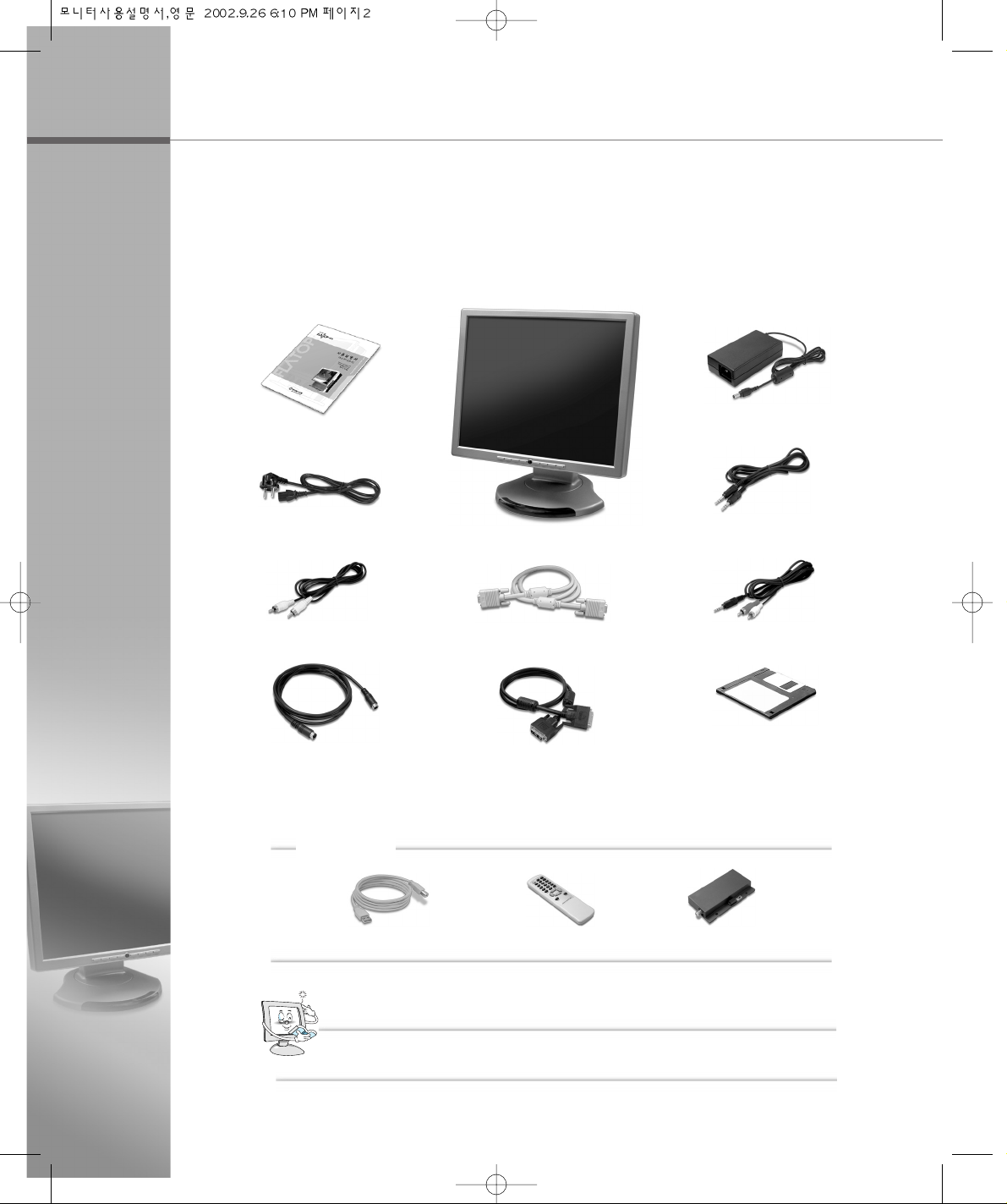
Unpacking
After opening the box, make sure the following items are provided with the monitor.
If you find that any of these items is missing or appears damaged, contact your
dealer immediately.
Optional
DVI Cable
Power Cord
DC Adapter
User Manual
VGA Signal Cable
Monitor
Audio Cable
Audio(RCA) Cable
Video(RCA) Cable
S-Video Cable
Diskette
(Monitor Driver)
The actual monitor and accessories may differ from those shown on the above figures.
NNoottee
USB Cable
Remote Control
TV Tuner
Page 3

CONTENTS
1.1 Features …………………………………………………………………… 1-2
1.2 Before You Use
…………………………………………………………… 1-3
Caution When Using the Power
……………………………………… 1-3
Caution when Installing the Monitor
…………………………………… 1-4
Caution when Moving the Monitor
…………………………………… 1-5
Caution when Using the Monitor
……………………………………… 1-6
1.3 Monitor Overview
………………………………………………………… 1-8
Front Side
…………………………………………………………………… 1-8
Rear Side
…………………………………………………………………… 1-9
1.4 Connecting the Peripheral Devices
………………………………… 1-10
1.5 Tilting Swiveling the Monitor
………………………………………… 1-14
Chapter 1 Installing the Monitor
Chapter 2 Installing the Monitor Driver
2.1 Installing the Monitor Driver Under Windows…………………… 2-2
Windows 98/ME
…………………………………………………………… 2-2
Windows 2000
……………………………………………………………… 2-3
Windows XP
………………………………………………………………… 2-4
2.2 Installing the Monitor Driver Under Linux
………………………… 2-7
Linux
…………………………………………………………………………… 2-7
Page 4
CONTENTS
Chapter 3 Adjusting the OSD
(On Screen Display)
Menu
A.1 TroubleShooting ………………………………………………………… A-2
The window doesn’t show anything
…………………………………… A-2
The color of the window is not normal
………………………………… A-3
The window is under a bias toward one side, or is not centrally
positioned
…………………………………………………………………… A-3
A faint letter is shown, or the phase is out of focus. Noise is also
generated horizontally
…………………………………………………… A-4
A.2 Specification
……………………………………………………………… A-5
Appendix Troubleshooting/Specification
3.1 Selecting and Adjusting the OSD(On Screen Display) Menu
………………………………………………………………………………… 3-2
Selecting and Adjusting the OSD Menu
……………………………… 3-2
3.2 The OSD(On Screen Display) Menu Functions
………………… 3-4
OSD Main Menu
…………………………………………………………… 3-4
OSD Sub Menu
…………………………………………………………… 3-5
Page 5

CE Conformity Notice
The Product herewith complies with requirements of the Low Voltage Directive
73/23/EEC and the EMC Directive 89/336/EEC and carries the ‘CE’ mark accordingly.
Confirms to the following hamonized European standards have been applied:
EMC : EN 55022 Class B: 1998
EN 55024: (EN 61000-4-2: 1995, A1:1998, EN61000-4-3:1996, EN 61000-4-4: 1995,
EN61000-4-5: 1995, EN61000-4-4: 1996, EN61000-4-8:1993 and
EN61000-4-11:1994)
EN61000-3-3: 1995, A1:98, A2:98
EN61000-3-3: 1995
FCC Compliance Statement
This equipment has been tested and found to comply with the limits for a Class B
digital device pursuant to Part 15 of the FCC Rules. These limits are designed to
provide resonable protection against harmful interference in a residential
installation.
This equipment generates, uses and can radiate radio frequency energy and if not
installed and used in accordance with the instructions, may cause harmful
interference to radio communication. However, there is no guarantee that
interference will not occur in a particular installation. If turning the equipment off and
on, the user id encouraged to try to correct the interference by one more of the following measures :
- Reorient or relocate the receiving antenna.
- Increase the separation between the equipment an receiver.
- Connect the equipment into an outlet in a circuit different from that to which the
receiver is connected.
- Consult the dealer or an experienced radio / TV technician for help.
W A R N I N G
Changes or modifications not expressly approved by the manufacturer could void
the user's authority to operate the equipment.
Page 6
mmeemmoo
Page 7
Features
Before You Use
Monitor Overview
Connecting the Peripheral
Devices.
Tilting and Swiveling the
Monitor
1.1
1.2
1.3
1.4
1.5
Page 8
1.1 Features
1-2
Adopt the 18.1” LCD(Liquid Crystal Display) Narrow Bezel panel which allows you
efficient use in a small space due to the slim design with wild screen.
Adopt the 18.1” TFT LCD Narrow Bezel Panel
High quality screen through direct digital signal from the computer.
Support DVI (Digital Video Interface)
It gives user an amplified stereo sound through internally installed speakers(2W).
AUDIO
The VESA DPMS(Display Power Management Signaling) function is available to reduce
power consumption by automatically switching the computer into the power saving mode if
the system doesn’t operate for a fixed period of time.
Power Consumption Economy Function
It can be embedded to use the USB without an external Hub.
Support the USB Ports (Optional)
Enable to watch TV after connecting antenna cable.
Enable to watch TV (Optional)
Page 9

1.2 Before You Use
Installing the Monitor
1-3
For your safety and the protection of your monitor, follow these precautions.
Caution When Using the Power
● Don’t plug the power adapter into a non-grounding power
outlet.
● Never touch the power plug with wet hands.
An electric shock accident may occur.
● Don’t plug with other electrical cords into one power outlet.
An electric shock or fire accident may occur.
● Only use the adapter provided with the monitor.
An electric shock or fire accident may occur.
● Don’t use a power cord or plug that is frayed or damaged.
An electric shock or ignition may be caused.
● Insert the plug completely so that the power supply unit can
be connected tightly.
Unsafe power connection may cause a fire.
Page 10
1-4
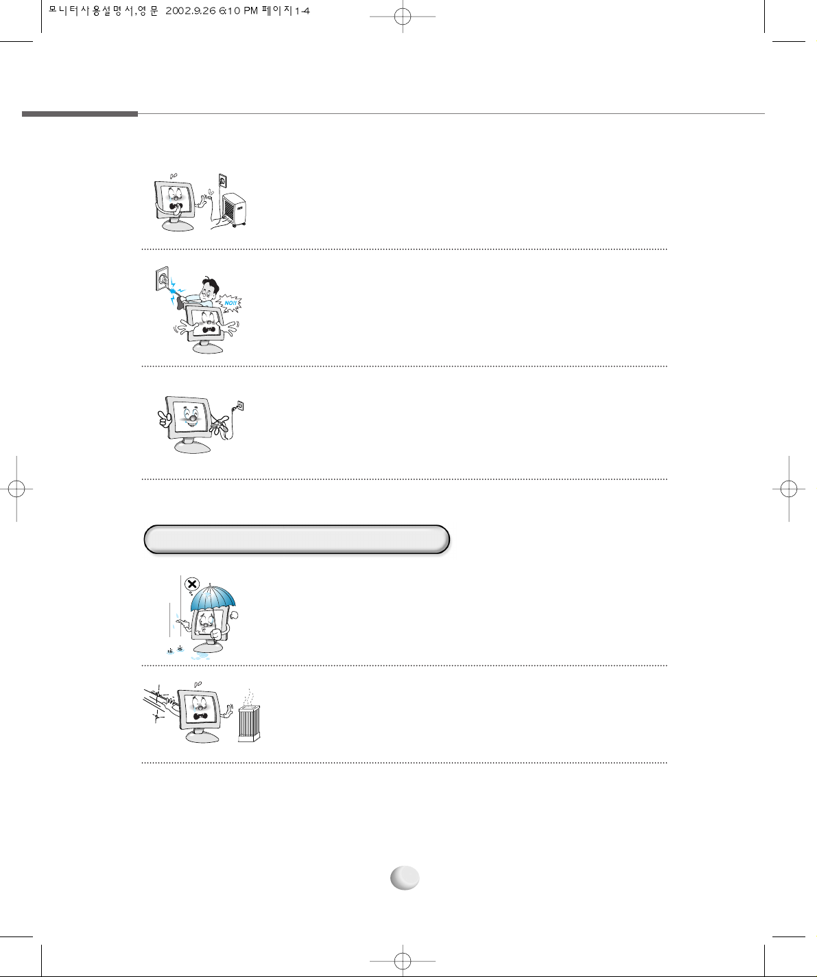
● Pull the power cord out when the monitor is not used for a long
time, or while you are away.
A dust covering may cause an electric shock, electric leakage, of fire
by heat generation, ignition, and insulation degradation.
● Select a cool, dry area and protect your monitor from
extremes in temperature, humidity, dust and smoke.
Accidents of electric shock, fire or failure may occur.
● Avoid direct sunlight or any other source of heat such as a
fireplace.
A fire or electric shock accident may be caused.
● Keep the power cord from proximity to a heating instrument.
The covering material of the cord may melt, causing a fire or
electric shock.
● Grasp the power plug at the base to remove it form the wall,
and pull firmly but gently.
If you yank at the cord the wire may be broken, causing ignition or
heat generation.
Caution When Installing the Monitor
Page 11
Installing the Monitor
1-5
● Place the monitor in a well-ventilated room.
A fire may be caused due to an increase in internal temperature.
● Note that air-flow holes must not be blocked such as a table
cloth or curtain.
A fire may be caused due to an increase in internal temperature.
● Turn off the monitor and disconnect all cables from the monitor
before moving the monitor.
● Be careful with the shock when moving the monitor.
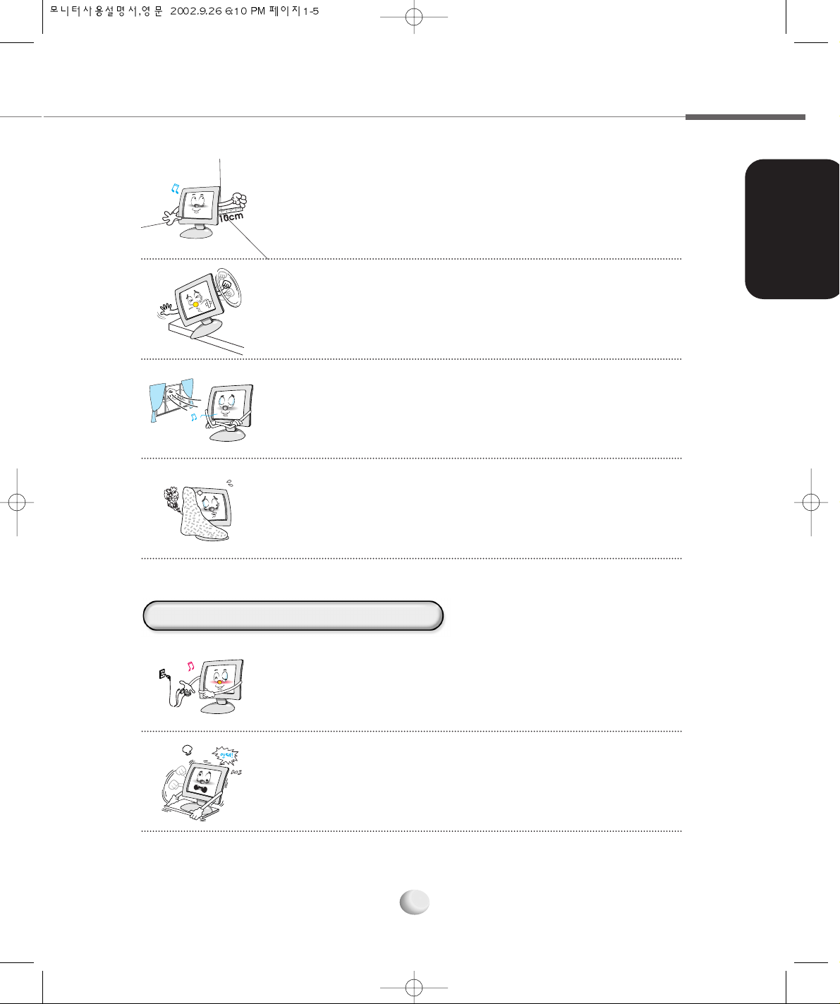
● Place the monitor at a proper distance (over 10 cm) away from
the wall for sufficient ventilation.
A fire may be caused due to an increase in internal temperature.
● Place the monitor on a stable and secure surface.
Fall or displacement of the monitor may cause an injury.
Caution When Moving the Monitor
Page 12
1-6
● Don’t scratch or jolt the monitor surface.
Damage or failure of the panel may be caused.
● Often take a rest to protect your eyes when you work
for a long time.
● Don’t block or obstruct the air-flow holes of the monitor.
A fire or damage of the monitor may be caused due to an
increase in internal temperature.
● Don’t spill liquids such as chemicals, water on the monitor.
A fire or electric shock accident may be caused.
● Never disassemble and repair the monitor but trained repair
engineers.
A fire or electric shock accident may be caused. If you need the
repair and adjustment, please contact the appropriate sales
agency or customer counsel window for check-ups.
● Take hold of the monitor with both hands setting the panel
forward.
If the monitor is dropped, contact the service center to check it for a
susceptibility to fire or electric shock.
Caution When Using the Monitor
Page 13
Installing the Monitor
1-7
● Don’t insert metals (such as coins, hair pins or ironware) or
flammable items (such as paper or matches) into the
monitor.
A fire or electric shock accident may be caused.
● Stop using in case of smoke or abnormal odors. Immediately turn
off the power and pull out the power cord from the wall and then
contact the service center.
Continuity of use in such a state may cause a fire or electric shock.
● Don’t spray any liquids directly onto the monitor.
An electric shock or fire accident may occur.
● Clean the LCD panel with a soft material such as cotton cloth
after removing the power cord from the monitor.
A fire or electric shock accident may be caused.
● The fluorescent light of the monitor contains a mercury which
could be exploded. Don’t discard or bury the monitor without
permission of the law concerned.
● Don’t press upon the panel or scratch the surface with your hands
or sharp item such as a nail, pens.
Damage or failure of the panel may be caused.
Page 14

1.3 Monitor Overview
1-8
This section identifies the name of each component of the monitor and briefly
describes the function of each component.
MENU Button
Displays or Exits the OSD
menu window.
POWER Button
Turns the monitor on and off.
SELECT Button
Selects the OSD menu item
and the submenu item to be
adjusted in the sub OSD menu
and save the modified value at any
selected item.(If you press
continuously every two times, the
input source will be switched.)
RIGHT Button
Increases the value of the
selected item. (Increases the
volume without pressing the
MENU Button.)
LEFT Button
Decreases the value of the
selected item. (Decreases the
volume without pressing the
MENU Button.)
DOWN Button
Moves to the down menu
item in the OSD menu window.
AUTO Button
Automatically adjusts the
optimal display status for the current
display mode. Otherwise, additionally
adjust the H/V Position, Clock, Phase in
POSITION menu.
IR Window
Receives the TV Remote Control input.
UP Button
Moves to the up menu item in the OSD menu window.
POWER LED
Indicates the monitor power status. Green : Monitor
activated Orange : Monitor standby/Monitor power
saving mode/VGA signal cable unhooked.
TFT LCD Display
Displays the current contents
of the display.
Front Side
When watching the TV
after connected TV
tuner(optional), use the
UP/DOWN Button without pressing the
MENU Button to select TV Channel.
NNoottee
Page 15

Installing the Monitor
1-9
▶ Self Diagnostics
If the signal cable is improperly connected
between the monitor and the computer,
the Self Diagnostics NO SIGNAL
message appears on the monitor.
▶ To use USB devices, at first you must connect the USB cable to USB connector on
the computer and USB UP port on the monitor, and then connect USB devices to
the USB UP port.
NNoottee
USB DOWN Port (Optional)
Connects USB devices.
TV Tuner(Optional)
Connects the TV
antenna cable.
AUDIO OUT Jack
Connects a set of headphones
or external speakers.
AUDIO IN Jack
Connects the audio cable to the LINE
OUT jack on the computer or the streo
jeck on the camcorder/VTR.
VIDEO Jack
Connects the video cable to the VIDEO
jack on the camcorder or VTR.
S-VIDEO Connector
Connects the s-video cable to the S-VIDEO
connector on the camcorder or VTR.
VGA Connector
Connects the VGA signal cable to the
VGA connector on the computer.
DC-IN Jack
Connects the DC adapter to input the power.
DVI Connector
Connects the DVI cable to the DVI connector on
the computer.
USB UP Port (Optional)
Connects the USB cable to
the USB connector on the
computer.
Rear Side
Page 16

1.4 Connecting the Peripheral Devices
Turn off the monitor, computer and other peripheral devices before connecting the
monitor and peripheral devices.
Connecting the power
Plug into the power outlet at 220V or 110V.
(The voltage is set automatically.)
1
Connecting the computer
Connect the VGA cable to the VGA connector or the
DVI cable to the DVI connector on the computer.
2
DC-IN Jack
VGA Connector
VGA Cable
VGA Connector
1-10
Connecting the VGA
Connector
DC Adapter
Power Cord
Page 17

Installing the Monitor
1-11
Connecting Audio Devices
Connect the audio cable to the AUDIO IN jack on the monitor and the LINE OUT jack on the
computer or connect the audio cable(RCA) cable to the AUDIO IN jack on the monitor and
the stereo jack on the camcorder/TV and connect a set of headphones or external speakers
to the AUDIO OUT Jack.
3
Set of
headphones
Set of
headphones
Set of
headphones
Set of
headphones
Set of
headphones
Set of
headphones
Set of
headphones
Set of
headphones
Set of
headphones
Set of
headphones
Set of
headphones
Set of
headphones
Set of
headphones
Set of
headphones
Set of
headphones
Set of
headphones
Set of
headphones
Set of
headphones
Set of
headphones
Set of
headphones
Set of
headphones
Set of
headphones
External Speakers
or
LINE OUT Jack
AUDIO IN Jack
AUDIO
OUT Jack
DVI Connector
DVI Connector
DVI Cable
Connecting the DVI
Connector
AUDIO Cable
AUDIO(RCA) Cable
Stereo Jack
Camcorder
Page 18

1-12
Connecting the Camcorder
Connect the S-VIDEO connector or VIDEO connector.
4
S-VIDEO Connector
VIDEO Connector
VIDEO
Connector
Camcorder
VTR
Camcorder
VTR
S-VIDEO
Connector
Page 19

Installing the Monitor
1-13
Connecting the TV Antenna
5
Connecting USB Devices (Optional)
At first, connect the USB cable to the USB UP port on the monitor and USB
connector on the computer and then, connect USB devices to the USB DOWN
port on the monitor.
6
TV Tuner(Optional)
USB Mouse
USB Keyboard
or
or
USB CCD
Camera
USB Cable
USB Connector
TV Antenna Cable
USB UP
Port
USB DOWN Port
Page 20

1.5 Tilting and Swiveling the Monitor
1-14
For optimum view, you can tilt the display vertically from -5 to 30 degree or swivel within
120 degree. When adjusting the display, grasp the left and right edges of the monitor.
Tilting
Swiveling
Page 21

Installing the Monitor Driver
Under Windows
Installing the Monitor Driver
Under Linux
2.1
2.2
Page 22

2.1
Installing the Monitor Driver Under Windows
2-2
Windows 98/ME
This section shows how to install the monitor driver under Windows or Linux by
using the monitor driver diskette provided. To install the monitor driver, please refer
to your OS in this section.
Turn on the computer and the monitor.
1
Insert the monitor driver diskette into the FDD on the computer.
2
Click My Computer on the Windows display and select Control Panel.
3
Double click the Display icon in the Control Panel window.
4
In the Display Properties window, click the Setting tab and then select Advanced.
5
Select the Monitor tab and click Change.
6
This wizard searches for updated drivers for
Click Next.
7
What do you want Windows to do?
Select Display a list of all the drivers in a specific location, so you can select the
driver you want Option and click Next.
8
Select the manufacturer and model of your hardware device.
Click Have Disk.
9
If it doesn’t show up the relevant model in device selection window, click List all
Device, select one of them and then click OK.
NNoottee
Page 23

Installing the Monitor Driver
2-3
Select the manufacturer and model of your hardware device.
Select ATEC NEOVIEW AL181N(Analog) option and click Next.
11
Window driver file search for device.
Click Next.
12
Windows has finished installing the driver you selected for your hardware device.
Click Finish.
13
Now, the model name of the monitor is changed. Close all windows opened
and restart the computer.
14
If you connect to your computer which is supported DVI, select ATEC NEOVIEW
AL181N(DIGITAL).
NNoottee
Windows 2000
Press Start, click Settings and Control Panel.
3
Click the Settings tab and then select Advanced.
5
Install From Disk
Click Browse, select <A:\> and click OK.
10
Turn on the computer and the monitor.
1
Insert the monitor driver diskette into the FDD on the computer.
2
Click Display icon in the Control Panel window.
4
Page 24

2-4
Pointing to where the diskette or driver is located, then click on OK.
▶ Insert a diskette to A drive bay, then press Enter.
▶ Pointing to where the driver is located:hard disk or network. Then press Enter.
▶ If you can’t correctly designate the driver route, then click search to find out the
right one.
11
Select the customer’s model in Model Selection screen. Then press Next.
12
Click Next.
13
Press Yes.
14
If Driver installation has been successfully completed is popped up, press Finish.
15
Now, the model name of the monitor is changed. Close all windows opened and
restart the computer.
16
Click Next.
8
Click Display a list of all the drivers in a specific location, so you can select the driver you
want. Then Click Next.
9
Click on Hardware.
10
Windows XP
Turn on the computer and the monitor.
1
Insert the monitor driver diskette into the FDD on the computer.
2
Select the Monitor tap and click Properties.
6
Choose Driver, then Update Driver...
7
Page 25

Installing the Monitor Driver
2-5
In the Display Properties window, click the Setting tab and then select Advanced.
5
Select the Monitor tab and click Properties.
6
Select the Driver tab, click Update Driver and then click Next.
7
Welcome to the Hardware Update Wizard
Select Install a list or specific location(Advanced) option and click Next.
8
Please choose your search and installation option
Select Don’t search. I will choose the driver to install option and click Next.
9
Please wait while the wizard installs the software..
Now, start installing the monitor driver.
13
Select the device drivers you want to install for this hardware.
Select ATEC NEOVIEW AL181N(Analog) and click Next.
12
If you connect to your computer which is supported DVI, select ATEC NEOVIEW
AL181N(DIGITAL).
NNoottee
Install From Disk
Click Browse, select <A:₩> and then click OK.
11
Select the device drivers you want to install for this hardware.
Click Have Disk.
10
Click the Start button on the Windows display and select Control Panel.
3
Double click the Display icon in the Control Panel window.
4
Page 26
2-6
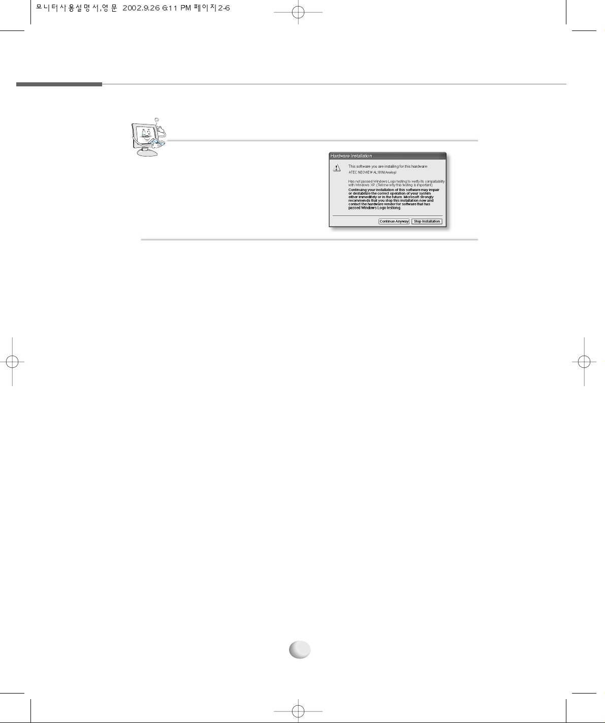
Completing the Hardware Update Wizard
Click Finish.
14
Now, the model name of the monitor is changed. Close all windows opened and
restart the computer.
15
This message may appear several
times during the installation of the
monitor driver.
Click Continue Anyway to continue.
This action will not harm your monitor
or system.
NNoottee
Page 27

2.2
Installing the Monitor Driver Under Linux
Installing the Monitor Driver
2-7
Linux
You’d make xf86config file to run X-WINDOW. Your monitor is surely and easily
configured with this file. This file will be made as running xf86config.
1
Press Enter in the first and second window after running xf86config file.
2
In third window, we come up with the mouse setting window.
3
Configure it as opt for user system.
4
Next will be the screen for selecting KeyBoard.
5
Configure it as opt for user system.
6
First, configure a horizontal frequency. Please refer to the horizontal frequency in
monitor manual. (User may directly input frequency.)
7
Next, configure a vertical frequency. Please refer to the horizontal frequency in
monitor manual. (User may directly input frequency.)
8
Then, configure a monitor.
9
Type in the model name of monitor. The monitor’s identification and description
(typed in here) aren’t directly related with the execution of X-WINDOW.
10
After complete with other hardware settings, run X-WINDOW.
11
As the configuration has been successfully finished, save a configuration file.
12
Now run X-WINDOW. Theoretically, it is supposed to be executed. But in some cases,
it won’t even start. In this case, edit a xf86config file.
13
Page 28

2-8
mmeemmoo
Page 29

Selecting and Adjusting the
OSD(On Screen Display)
Menu
The OSD(On Screen Display)
Menu Functions
3.1
3.2
Page 30

3.1
Selecting and Adjusting the OSD
(On Screen Display)
Menu
3-2
You can select the OSD menu in the OSD window by using all the control buttons under the
display. To change the current settings or adjust it to what you prefer, please follow these steps.
Selecting and Adjusting the OSD menu
Press the MENU button to open the OSD menu window.
1
Press the UP/DOWN button to move the desired main menu item.
2
The main menu item you moved is highlighted, press the SELECT button.
3
Press the UP/DOWN button to move the desired submenu item.
4
The submenu item you moved is highlighted, press the SELECT button.
5
Press the LEFT/RIGHT button to modify the current value.
6
Press the SELECT button to save the modified value.
7
MENU
UP/DOWN
SELECT
(Select the main menu item)
MENU
(Exit the OSD menu window)
SELECT
(Save the modified value)
SELECT
(Exit the Submenu)
UP/DOWN
SELECT
(Exit the OSD menu)
LEFT/RIGHT
UP/DOWN
SELECT
(Select the submenu item)
UP/DOWN
or
Page 31

3-3
OSD window will be disappeared in a few seconds if there’s no input on OSD
windows.
NNoottee
To close the OSD menu window, press the MENU button or select ‘EXIT’ (in the
submenu window) in order.
8
Adjusting the OSD Screen
Page 32

3.2
The OSD
(On Screen Display)
Menu Functions
3-4
OSD Main Menu
● BRIGHTNESS/CONTRAST
Controls the brightness and contrast of the display.
The OSD main menu window that you can select and adjust the OSD menu to the
optimal display appears by pressing the MENU button.
● COLOR
Changes the value of the display color (Red, Green, Blue).
● POSITION
Adjusts the horizontal and vertical position, clock and phase of the display.
● SETUP
Controls the OSD position, OSD time, and input source of the display.
● EXIT
Exits the OSD menu.
MICOM Version
Screen Frequency
Screen Resolution
Page 33

3-5
The OSD submenu window appears by selecting the main menu.
BRIGHTNESS : Controls the brightness of the display.
CONTRAST : Adjusts the level of difference between light and dark areas of the display.
EXIT : Exits BRIGHTNESS/CONTRAST menu.
BRIGHTNESS/CONTRAST
RED : Changes the value of red.
GREEN : Changes the value of green.
BLUE : Changes the value of blue.
EXIT : Exits COLOR menu.
COLOR
OSD Sub Menu
Adjusting the OSD Screen
Page 34

3-6
OSD POSITION : Adjusts the position of the OSD window.
OSD TIME : Selects the waiting time the OSD window fades away on the screen within
100 sec. (Dafault : 15 sec)
INPUT SOURCE : Selects the input source according to the display device you connected.
- DIGITAL : Selects when connect the DVI cable to the DVI connector of the computer.
- ANALOG : Selects when connect the VGA cable to the VGA connector of the computer
SETUP
HORIZONTAL : Adjusts the horizontal position of the display.
VERTICAL : Adjusts the vertical position of the display.
CLOCK : Increases or decreases the number of pixel to adjust the horizontal size.
PHASE : Adjusts the focus and clarity of the display.
EXIT : Exits POSITION menu.
POSITION
Page 35

3-7
- S-VIDEO : Selects when connect the S-VIDEO cable to the S-VIDEO connector of
the camcorder.
- COMPOSITE : Selects when connect the VIDEO cable to the VIDEO jack of the
camcorder.
EXIT : Exits SETUP menu.
When you press the SELECT button in Windows display, the current input source
will be appeared and it will be switched to ANALOG
DIGITAL COMPOSITE
S-VIDEO TUNER(Optional) by pressing the SELECT button every two times
continuously. The screen will be blanked unless the input source is correct. Select
the proper input source according to the display device you connect.
CCaauuttiioonn
▶ The OSD menu when
connect the TV tuner(optional)
The OSD menu window
appears with pressing MENU
button after connecting the
TV tuner.
COLOR
● SHARPNESS : Adjusts the level of display sharpness.
● COLOR : Adjusts the amount of RGB(Red, Green, Blue) color from white
color in the display.
● TINT : Adjusts the tint of the display color.
● EXIT : Exits COLOR menu
NNoottee
Adjusting the OSD Screen
Page 36

3-8
CHANNEL
● AIR/CATV
- AIR : Selects when watching the air TV.
- CATV : Selects when watching the CATV.
● AUTO CHANNEL : Automatically memorize all the active TV or CABLE channels.
- START : Starts detecting the active channels.
- STOP : Stops detecting the active channels.
● MANUAL CHANNEL : Manually memorize or erase the TV or CABLE channel.
● FINE : Selects when the display color is blur or unfocused.
● EXIT : Exits CHANNEL Menu.
▶ The OSD menu when connect S-VIDEO connector
▶ The OSD menu when connect VIDEO jack
※ For more details, please refer to 2.1 Selecting and Adjusting the OSD(On Screen
Display) Menu and 2.2 The OSD(On Screen Display) Menu Functions
in this chapter.
The COLOR submenu of the S-VIDEO and VIDEO OSD MENU is same as the COLOR
submenu of the TV TUNER.
NNoottee
Page 37

TroubleShooting
Specification
A.1
A.2
Page 38

A.1 TroubleShooting
A-2
Please check the below particulars before you contact the service center to notify an
abnormality of the monitor.
The window doesn’t show anything
Is the monitor power cord inserted?
Please connect the power cord correctly to the concent.
Is the power turned off?
Please press the power button.
Is the power turned on and the power pilot lamp blinking amber?
The monitor is in the power saving mode. Please therefore move the mouse or press
any key on the keyboard.
Is the message
Out Of Range shown?
If a power indicating lamp of amber color blinks, press any key to go back to previous
mode. As it passes over the frequency limit of horizon (31.5-80kHz) and verticality (60-75
Hz) in computer (video card), you’d reconfigure it as referring to the specification of this
manual. (If you install the monitor driver that we have provided, it won’t come up with the
message
OUT OF RANGE .)
Is the message
No Input Signal shown?
It shows up as computer changes to power-saving mode or the signal cable between
computer and monitor isn’t rightly connected. Move your mouse or press keyboard
button. But it won’t still show you a right screen, then recheck a signal cable connection.
Page 39

TroubleShooting
A-3
Has a discoloration (into 16 colors) of the screen occurred?
Set the number of colors to more than 256 colors. On the Windows 95/98/XP,
perform the following process [Control Panel]
[Display] [Setting]
[Color Table/Screen Resolution] [256 Colors] [OK]
Do you see a spot on the screen?
You may see a few spots (in red, green, white and black) on the screen during the
operation. Occurrence of such a phenomenon is not a failure but a characteristic
of the LCD panel, and therefore has no relation to the performance of the monitor.
Is the positional adjustment made correctly?
Press the AUTO button, then the screen will be adjusted automatically into
the optimal state applicable to the current mode.
If you are not satisfied with the auto adjustment, you can directly adjust the
H Position (Horizontal Position), V Position (Vertical Position), and Clock
(Horizontal Size) of the OSD menus.
Is the Phase adjustment made properly?
Press the AUTO button, then the screen will be adjusted automatically into
the optimal state applicable to the current mode.
If you are not satisfied with the auto adjustment, you may manually adjust
the Phase (Focus) of the OSD menus.
The color of the window is not normal
The window is under a bias toward one side, or is not centrally positioned
Page 40

A-4
Is the screen set in the best state?
While you are using this product in the mode of 1280×1024 and 60Hz, the
best condition of the screen is available. In the mode of VGA(640×480),
SVGA(800×600) or XGA (1024×768), the outline of a letter may be seen
dimly or unevenly.
A faint letter is shown, or the phase is out of focus. Noise is also generated horizontally
Page 41

A.2 Specification
Specification
A-5
The details of product specification can be changed without notice to improve the
product.
LCD Type a-Si active matrix TFT-LCD
Size 18.1 (459.74mm)
Pixel Pitch 0.2805mm×0.2805mm
Luminance, white 250 cd/m2
Contrast Ratio 350 : 1(typical)
View Angle(H/V) U/D:±80°, R/L:±80°
Interface Analog / Digital
Frequency Horizontal frequency 31.5~80 kHz
Vertical frequency 60~75 Hz
Resolution Maximum SXGA 1280×1024
Color Color depth 8 bit(16,777, 216 Color)
Signal Input Input Connectors 15pin D-Sub, DVI-D, RCA, S-VHS
User’s control Auto Configuration, Brightness, Contrast,
H-Position, V-Position, Color RGB, Phase,
Clock, Volume etc.
Audio Output Stereo 2Watt×2
Special Low-Radiation TCO 99
Features Angle Control Swivel : 120°, Tilt : -5°~30°
Special features Dual Interface
Consumption On Working 40Watts(Max.)
Power DPMS VESA DPMS Standard
Option TV NTSC, PAL/SECAM
USB UP Port 1EA, DOWN Port 2EA
Page 42

Factory-specified Mode
A-6
1
2
3
4
5
6
7
8
9
10
11
12
13
Factory-specified Mode Horizontal Vertical
Frequency(kHz) Frequency(kHz)
VGA
VGA
VGA
VGA
VGA
SVGA
SVGA
SVGA
XGA
XGA
XGA
SXGA
SXGA
640×350
640×480
640×480
640×480
720×400
800×600
800×600
800×600
1024×768
1024×768
1024×768
1280×1024
1280×1024
31.47
31.47
37.86
37.50
31.47
37.88
48.68
46.88
48.36
56.48
60.02
64.0
79.98
70
60
72
75
70
60
72
75
60
70
75
60
75
The indication in above diagram and actual value shall not be
always coincident. This product automatically adjusts for
optimum condition by itself.
In case of any trouble in user’s set-up, it automatically returns to
the initial set-up mode.
CCaauuttiioonn
Page 43

Customer
’’
s Card
Product name : Model name :
Data of Purchase :
Customer’s Name : Tel. Address
Customer’s Name : Tel. Address
Warranty
Product name : Model name :
Data of Purchase :
Customer’s Name : Tel. Address
Agency Name : Tel. Address
You must present this warranty containing the date of purchase when you ask for service.
Please keep this warrant in a safe place.
1. The warranty of this product will be based on the contents in the warranty.
2. The warranty period is calculated from the date of purchase, please write down the date of purchase.
3. To calculate the date of purchase this product, please bring your sales recipt taken from your dealer.
4. The warranty period lasts one year for normal use.
5. In the case of a separate agreement, the descriptions of the main agreement will be applied.
One-year
warranty
 Loading...