

Page 1
Features
Broadband - For sweep measurements
High Gain - Lower Floor Noise for Emissions
Two year warranty
Individual calibration
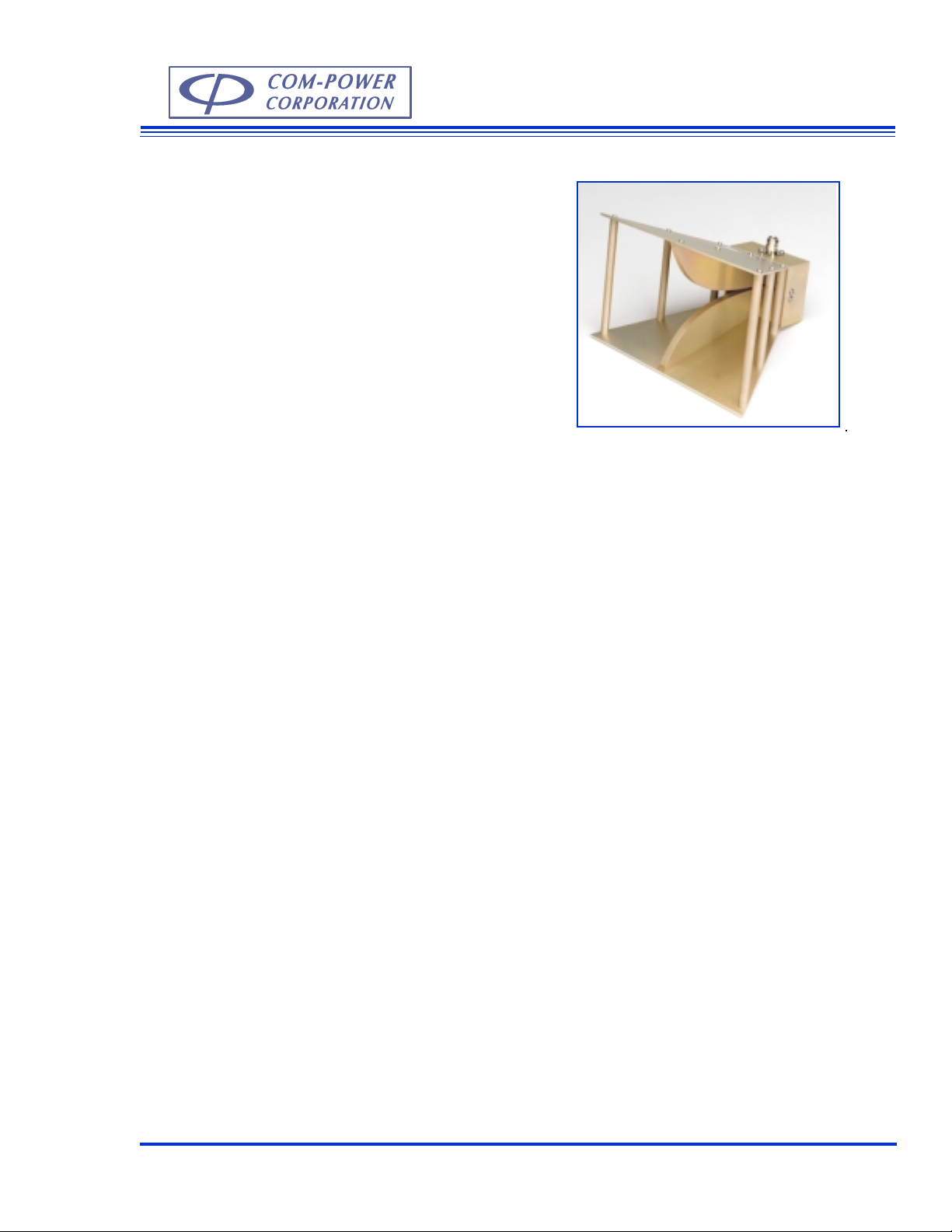
Horn Antenna
AH-118
Description
The Horn antenna Model AH-118 is a standard
broadband double ridged waveguide horn antenna. This antenna is linearly polorized and is
designed specifically for EMC measurements
for the 1-18 GHz frequency range.
The AH-118 Horn antenna can be used for emissions and immunity testing. The gain of this
Horn antenna is at least 6.1 dBi over the entire
frequency range. Model AH-118 can accept up
to 300 Watts input power in continuous mode.
This antenna is constructed using light weight
aluminum with a corrosion resistant conductive
coating. The mounting base of Model AH-118
has 1/4 inch x 20 threads. This allows the antenna to be mounted on a tripod (Model AT-100)
or a tripod with matching threads.
Each antenna is individually calibrated at 3
meters. The calibration data and certificate will
be shipped with each antenna.
Application
This antenna is suitable for ANSI 63.4, CISPR16,
EN 55022, FAA and other EMC standards that
require emissions and immunity testing.
The high gain reduces input power requirements
to generate high electromagnetic field levels for
immunity testing. High gain also increases antenna sensitivity to low level signals.
During emissions measurement, the field strength
(dBV/m) is calculated by adding the antenna
factor (dB/m) to the voltage measured (dBV) at
the antenna terminals.
For immunity testing, the input power requirement P in Watts to generate E Electric Field
Strength in V/m at a distance in D meters can be
calculated by using the following formula:
P = E2 x D2 / 30 x Numeric Gain
G = 20 log F -29.79- AF
G = 10 log (Numeric Gain)
Where
G= gain in dBi
F = Frequency in MHz
AF = antenna factor in dB
Com-Power Corporation (949) 587 - 9800 www. com-power.com sales@com-power.com
A-15
Page 2
Specifications
Frequency Range: 1 GHz - 18 GHz
Input Power: 300 Watts continious
VSWR: 2.0 : 1
Polorization: Linear
Impedance: 50 Ohm
Connector type: N Female
Weight: 4 lb. max.
Size: 7.8" X 9.5" X 5.6" max.
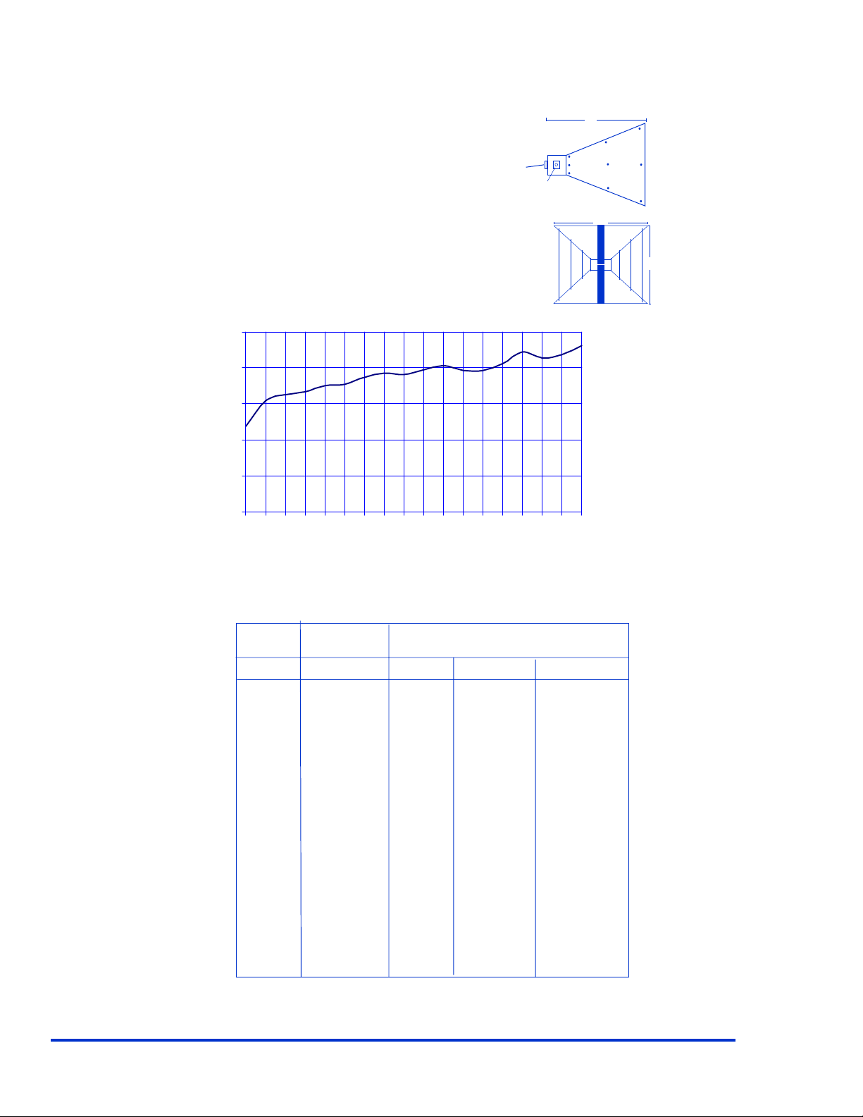
Typical Antenna Factors:
50.0
40.0
30.0
20.0
Factors (dB/m)
10.0
Tripod
Mounting
Block
Top View
Type N
Connector
Front View
7.8"
9.5"
5.6"
0.0
123456789101112131415161718
Frequency (GHz)
Field strength (dBV/m) = Output measured (dBV) + Antenna Factor (dB/m)
Typical Antenna Gain and Power Requirement at 1 meter antenna spacing:
Freq. Gain Power requirement (Watts)
GHz dBi 10V/m 20 V/m 100 V/m
1 6.4 0.8 3.0 76.2
2 5.3 1.0 3.9 97.7
3 7.2 0.6 2.6 64.2
4 8.9 0.4 1.7 43.4
5 9.1 0.4 1.6 41.1
6 10.4 0.3 1.2 30.6
7 9.7 0.4 1.4 35.6
8 9.8 0.4 1.4 35.1
9 11.1 0.3 1.0 25.9
10 10.7 0.3 1.1 28.3
12 12.5 0.2 0.8 18.8
14 11.9 0.2 0.9 21.4
16 11.5 0.2 0.9 23.6
18 9.2 0.4 1.6 39.9
All values are typical values unless specified.
All specifactions are subject to change without notice.
Com-Power Corporation 20621 Pascal Way, Lake Forest, California 92630 (949) 587 - 9800 www.com-power.com Rev 1201
A-16
 Loading...