

Page 1
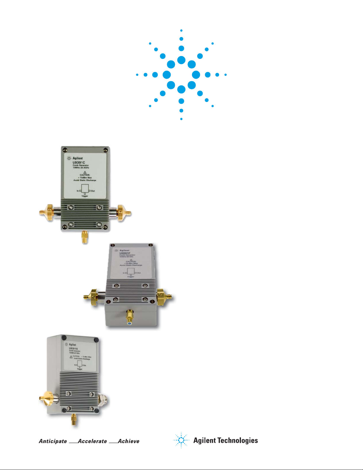
Agilent U9391C/F/G
Comb Generators
U9391C (10 MHz to 26.5 GHz)
U9391F (10 MHz to 50 GHz)
U9391G (10 MHz to 67 GHz)
Technical Overview
Key Features
• Excellent amplitude and phase flatness enable it to be
used as a precision calibration phase reference standard
for the NVNA
• NIST referenced phase calibration guarantees a reliable
reference to international standards
• Embedded calibration data can be easily accessed via the
plug-and-play USB interface
• The USB interface facilitates frequency divider control
and calibration data retrieval via the PNA-X
• Rugged 1.85-mm, 2.4-mm, and 3.5-mm bulk-head connectors guarantee high repeatability throughout multiple
connects and disconnects
• Sine to square wave converter provided as standard accessory (U9391F/G only) ensures the comb generator functions
at its optimum level for output frequencies above 26.5 GHz
• Handgrip (U9391G only) designed for better gripping and
as heat insulator for user handling
Page 2

Description
The U9391C/F/G comb generators were developed to provide precision phase
calibration, referenced to the National Institute of Standards and Technology
(NIST) standard, for non-linear measurements using the PNA-X nonlinear vector
network analyzer (NVNA) 1. NVNA component characterization software
converts a 4-port PNA-X with Option 510 into an innovative, high-performance,
non-linear network analyzer which uses U9391C/F/G comb generators as a
precision phase calibration standard. Comb generators generate frequency
harmonics at integer multiples from an RF input signal. Generally, comb
generators available in the open market today are made with SRD diodes,
U9391C/F/G comb generators are based on Agilent InP MMIC technology 2 to
ensure superior phase stability of the combs.
U9391C/F/G modules are solid state devices which provide excellent phase and
amplitude flatness in the combs making them ideal for use in phase calibration
applications. A built-in frequency divider, selectable via the PNA-X, reduces the
noise of the combs. You can set drive frequency at 1, 2 , 4, 8 or 16 times the
pulse repetition frequency (PRF). Combining a frequency divider with a wide
input signal frequency range allows for a broad range of possible harmonics
spacing, making this suitable for characterizing non-linear devices. This
module has a trigger output which enables synchronization with the pulse’s
repetition frequency. Calibration data stored inside the U9391C/F/G can be
accessed directly by the PNA-X via the USB interface for phase calibration. The
comb generator comes with the option of female or male output connectors.
Agilent’s new patented-pending comb generators offers the advantage of wide
bandwidth output (10 MHz - 26.5 GHz, 10 MHz to 50 GHz, and 10 MHz to 67 GHz)
and small minimum tone spacing (10 MHz). When driven by low phase noise
sources, this comb generator will operate at frequencies lower than 10 MHz,
but performance is not guaranteed. The input power and fundamental frequency
have lower sensitivity than other comb generators. This means a comb generator calibrated at a single power level and frequency can be used across a wide
range of input power levels and frequencies.
Accurate transfer
of NIST standard
Agilent characterizes the U9391C/F/G comb generators’ phase standard using
a precision calibration technique that is traceable to NIST. Each comb generator’s
amplitude and phase data is stored in the module’s memory. The N5242A-510
NVNA component characterization software uses the phase data from the
U9391C/F/G to calculate the non-linear error terms for the PNA-X network
analyzers.
1. NOTE: The U9391C/F/G was designed for use with the PNA-X ONLY.
2. Indium phosphide monolithic microwave integrated circuit
2
Page 3
Applications
Network analyzer
compatibility
Comb generator and
PNA-X configurations
The U9391C comb generator is controlled by the N5242A 26 GHz PNA-X network
analyzer via a USB connection (options required: 400, 419, 080, 510). The U9391F
comb generator can be used with the N5245A 50 GHz PNA-X network analyzer via
USB connection (options required: 400, 419, 080, 510). The U9391G comb generator
can be used with the N5247A 67 GHz PNA-X network analyzer via USB connection
(options required: 400, 419, 080, 510). The N5242A/45A/47A PNA-X network
analyzers can be upgraded to perform nonlinear component characterization.
Two units of U9391C/F/G are required to carry out non-linear measurements.
One unit is used as the phase reference module and the second unit as the
phase calibration module.
The U9391C/F/G units need to be powered by separate power supplies. The
NVNA software automatically controls the U9391C/F/G units via USB after they
have been designated as phase reference and calibration modules respectively.
The phase calibration procedure is carried out by following the on-screen
instructions on the PNA-X. After completing the calibration, the U9391C/F/G
unit used for phase calibration can be disconnected. The other unit will be used
as the phase reference and must remain connected while the measurement is
carried out.
OUT
Calibration
phase reference
IN
11636B
Power
Divider
IN
DUT
OUT Measurement
phase reference
RCVR B
IN
3
Page 4

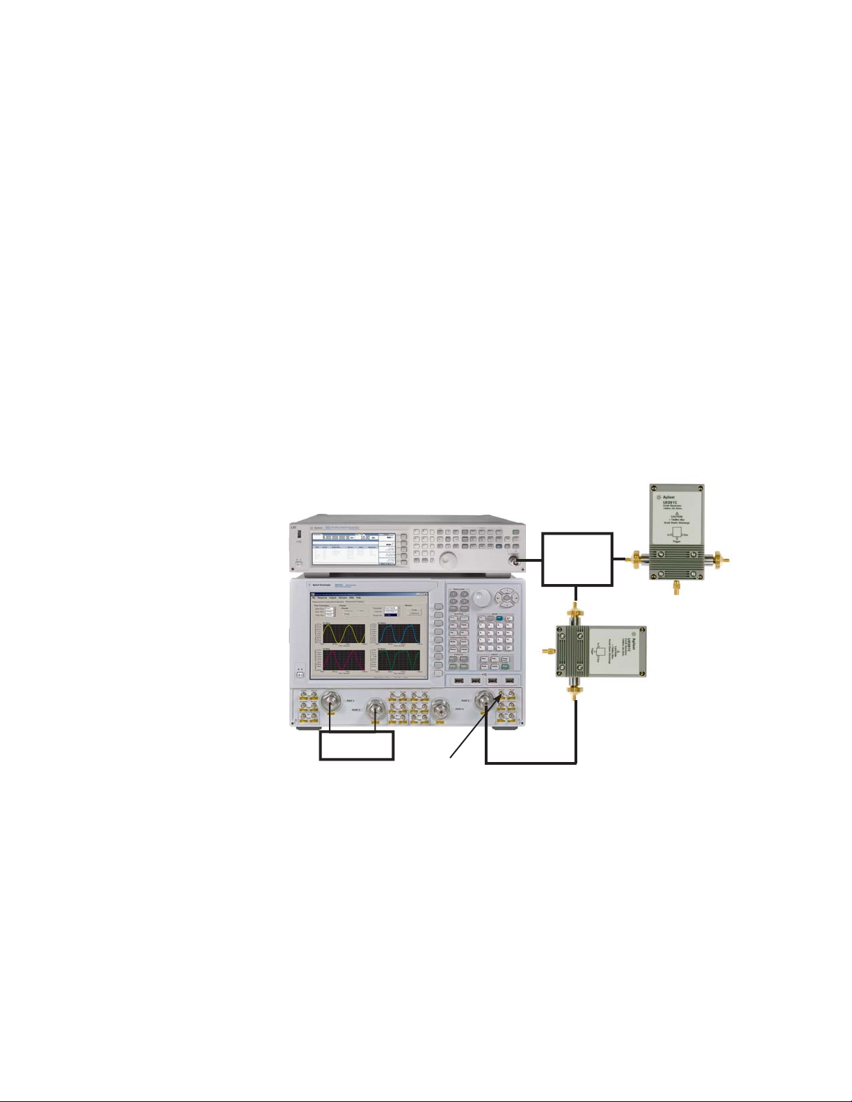
Alternative configuration
OU
with squaring unit
If a signal generator is not available, the 10 MHz reference output on the back
panel of the PNA-X can be used as a signal source. However, the U9391-60009
sine to square wave converter is needed as the comb generator will not function
at its optimum level for output frequencies above 26.5 GHz, with a sine wave
input of less than 100 MHz. Therefore, U9391-60009 is included as a standard
accessory for U9391F and U9391G.
PNA-X Back Panel
DC power supply
compatibility
PNA-X Front Panel
DUT
RCVR B IN
Measurement
Phase Ref
10 MHz
Sine to
Square
Wave
Converter
IN
11636B
Power
Divider
Calibration
Phase Ref
T
The U9391C/F/G can be powered by any DC power supply that is capable of
supplying at least 300 mA (nominal) at 15 ± 10% Vdc 1 (via the banana plug
cables provided).
Recommended DC power supply for U9391C/F: E3620A
Recommended DC power supply for U9391G: E3615A
Compatible DC power supply: All E36XXA series power
supply (except E3612A
and E3614A)
U9391C/F/G Drive Power Supply Specification
Specifi cations U9391C/F U9391G
Voltage +15V +/- 10% Vdc +15V +/- 10% Vdc
Current 300 mA (nominal) 850 mA (nominal)
1. Current drawn will change when drive
voltage changes.
4
Page 5

Options
Output connectors
Specifications
Option FFF – female (output port)
Option FFM – male (output port)
1
Specifications refer to the performance standards or limits against which the
U9391C/F/G comb generators are tested.
Typical characteristics are included for additional information only and they are not specifi cations.
These are denoted as “typical”, “nominal” or “approximate” and are printed in italic.
Specifi cations U9391C U9391F U9391G
Output frequency range
Input frequency range
Input power range
Min output power per picket
Amplitude fl atness vs. output frequency
Amplitude fl atness vs. input power
Phase fl atness/degree
Pulse width
Divide ratio
Input return loss, S11
Output return loss, S22
at 10 MHz Input PRF -80 dBm -95 dBm -100 dBm
at 10 MHz Input PRF < 12 dB < 25 dB < 40 dB
10 MHz to 3 GHz
3 GHz to 20 GHz
20 GHz to 26.5 GHz
26.5 GHz to 28 GHz
28 GHz to 38 GHz
38 GHz to 45 GHz
45 GHz to 50 GHz
50 GHz to 67 GHz
10 MHz to 6 Ghz > 10 dB > 10 dB > 10 dB
10 MHz to 10 GHz
10 GHz to 20 GHz
20 GHz to 26.5 GHz
26.5 GHz to 45 GHz
45 GHz to 50 GHz
50 GHz to 67 GHz
10 MHz to 26.5 GHz 10 MHz to 50 GHz 10 MHz to 67 GHz
10 MHz to 6 GHz 10 MHz to 6 GHz 10 MHz to 6 GHz
-15 to +15 dBm -15 to +15 dBm -15 to +15 dBm
0.1dB (typical) 0.5dB (typical) 1.0 dB (typical)
± 8.5
± 6.5
± 8.5
< 23 ps < 23 ps < 23 ps
1,2,4,8,16 1,2,4,8,16 1,2,4,8,16
> 10 dB
> 10 dB
> 10 dB
+ 10 /- 10
+ 10 /- 10
+ 10 /- 10
+ 10 /- 10
+20 / -10
+20 / -15
+20 / -15
> 10 dB
> 10 dB
> 7 dB
> 7 dB
> 5 dB
+ 10 /- 10
+ 10 /- 10
+ 10 /- 10
+ 20 /- 10
+20 / -10
+20 / -15
+20 / -15
+35 / - 35
> 10 dB
> 10 dB
> 7 dB
> 7 dB
> 5 dB
> 5 dB
Environmental
Specifications
U9391C/F/G comb generators are designed to fully comply with Agilent’s product
operating environment specifications. The following are the summarized
environmental specifications for these products.
Specifi cations Limits
Temperature
Operating
Storage
Error corrected range
Cycling
0 to +40 °C
–40 to +70 °C
23 °C ±3 °C
–65 to +85 °C, 10 cycles at 20 °C per minute. 20 minutes dwell time per MIL-STD-883F, Method 1010.8,
Condition C (modifi ed)
Relative humidity
Operation
Storage
50% to 95% RH at 40 °C, 24 hours cycling, repeated 5 times
90% RH at 65 °C, one 24 hour cycle
Shock
End-use handling shock
Transportation shock
Half-sine waveform, 2-3 ms duration, 60 in/s (1.6 ms) delta-V
Trapezoidal waveform, 18-22 ms duration, 337 in/s (8.56 ms) delta-V
Vibration
Operating
Survival
Random: 5 to 500 Hz, 0.21 grms, 10 min/axis
Random: 5 to 500 Hz, 2.09 grms, 10 min/axis
Swept sine: 5 to 500 Hz, 0.5 grms, 10 min/axis, 4 resonance search, 10 min dwell
Altitude
Operating
Storage
< 4,572 meters (15,000 ft)
< 15,000 meters (50,000 ft)
ESD immunity
Direct discharge
Air discharge
1
8.0 kV per IEC 61000-4-2
15 kV per IEC 61000-4-2
1. To outer conductor
1. Note: The U9391C/F/G was specially designed for use with the PNA-X ONLY.
5
Page 6
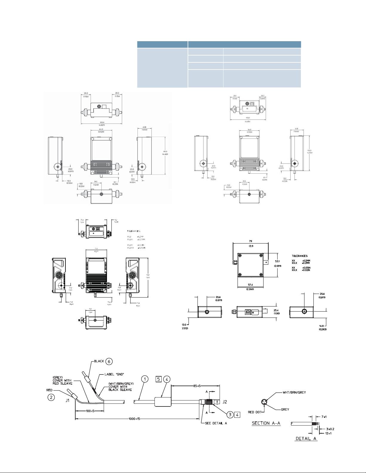
Mechanical
Dimensions
Mechanical dimension for U9391C Mechanical dimension for U9391F
Specifi cations U9391C/F/G
Input 0 to -0.0508 mm (0 to -0.0020”)
Pin Depth
Net weight
Physical weight of U9391C/F/G
Output 0 to -0.0508 mm (0 to -0.0020”)
Trigger 0 to -0.1270 mm (0 to -0.0050”)
U9391C/F
0.370 kg
U9391G
0.435 kg
Mechanical dimension for U9391G
Mechanical dimension for cable U9391-20013
Note: The 87205-20006 can also be used.
Mechanical dimension for U9391-60009
Squaring circuit for U9391F/G
6
Page 7
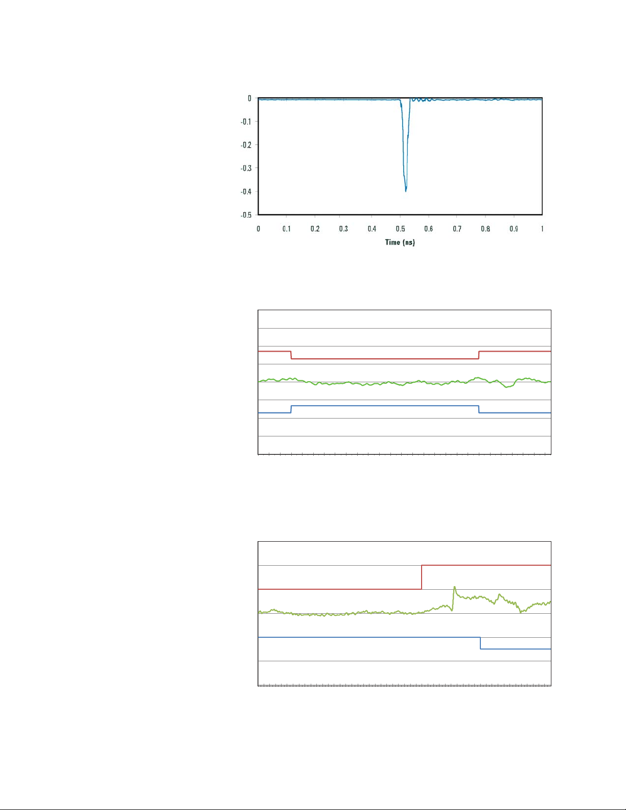
Typical Performance
160
165
170
175
180
185
190
195
05101520
25
Phase (deg)
Freq (GHz)
150
160
170
180
190
200
210
0510152025303540
45
Phase (deg)
Freq (GHz)
Figure 2. U9391C/F pulse
Figure 3. U9391C Comb Generator Phase at 10 MHz PRF
Figure 4. U9391F Comb Generator Phase at 10 MHz PRF
7
Page 8

Typical Performance
140
150
160
170
180
190
200
210
220
051015202530354045505560
65
Phase (deg)
Freq (GHz)
-90
-85
-80
-75
-70
-65
-60
05101520
25
Output Power (dBm)
Freq (GHz)
-100
-95
-90
-85
-80
-75
-70
-65
-60
0510152025303540
45
Output Power (dBm)
Freq (GHz)
continued
Figure 5. U9391G Comb Generator Phase at 10 MHz PRF
Figure 6. U9391C Comb Generator Output Power at 10 MHz PRF
1. This graph shows the raw performance
data for the NVNA application, the phase
performance can be corrected with the
calibration data.
Figure 7. U9391F Comb Generator Output Power at 10 MHz PRF
8
Page 9

Typical Performance
-110
-100
-90
-80
-70
-60
-50
051015202530354045505560
65
Output Power ( dBm)
Freq (GHz)
continued
Figure 8. U9391G Comb Generator Output Power at 10 MHz PRF
Ordering Information
Product
U9391C 26.5 GHz Comb Generator
U9391F 50 GHz Comb Generator
U9391G 67 GHz Comb Generator
Connector options
There are two connector options available for the Agilent U9391C/F/G comb generator.
• Option FFF - female (output connector)
• Option FFM - male (output connector)
U9391-60009 squaring circuit is available for the U9391F and U9391G only.
1
1
1
1. U9391C/F/G comb generators are devices (patented
design) designed as a phase reference standard for
N5242A/N5245A/N5247A PNA-X network analyzers.
PNA-X Options 400, 419, 080, 510 are required.
www.agilent.com/find/pnax
9
Page 10

www.agilent.com
s
www.agilent.com/find/mta
www.agilent.com/find/pnax
myAgilent
myAgilent
www.agilent.com/find/myagilent
A personalized view into the information most
relevant to you.
Agilent Channel Partners
www.agilent.com/find/channelpartners
Get the best of both worlds: Agilent’s
measurement expertise and product
breadth, combined with channel partner
convenience.
Three-Year Warranty
www.agilent.com/find/ThreeYearWarranty
Agilent’s combination of product reliability
and three-year warranty coverage is another
way we help you achieve your business goals:
increased confidence in uptime, reduced cost
of ownership and greater convenience.
Agilent Advantage Services
www.agilent.com/find/AdvantageServices
Accurate measurements throughout the
life of your instruments.
Agilent Electronic Measurement Group
DEKRA Certified
ISO 9001:2008
Quality Management SystemQuality Management Sy
www.agilent.com/quality
For more information on Agilent Technologies’
products, applications or services, please
contact your local Agilent office. The
complete list is available at:
www.agilent.com/find/contactus
Americas
Canada (877) 894 4414
Brazil (11) 4197 3600
Mexico 01800 5064 800
United States (800) 829 4444
Asia Pacifi c
Australia 1 800 629 485
China 800 810 0189
Hong Kong 800 938 693
India 1 800 112 929
Japan 0120 (421) 345
Korea 080 769 0800
Malaysia 1 800 888 848
Singapore 1 800 375 8100
Taiwan 0800 047 866
Other AP Countries (65) 375 8100
Europe & Middle East
Belgium 32 (0) 2 404 93 40
Denmark 45 45 80 12 15
Finland 358 (0) 10 855 2100
France 0825 010 700*
*0.125 €/minute
Germany 49 (0) 7031 464 6333
Ireland 1890 924 204
Israel 972-3-9288-504/544
Italy 39 02 92 60 8484
Netherlands 31 (0) 20 547 2111
Spain 34 (91) 631 3300
Sweden 0200-88 22 55
United Kingdom 44 (0) 118 927 6201
For other unlisted countries:
www.agilent.com/find/contactus
(BP-3-1-13)
Product specifications and descriptions
in this document subject to change without
notice.
© Agilent Technologies, Inc. 2013
Published in USA, March 21, 2013
5989-7619EN
 Loading...