

Page 1
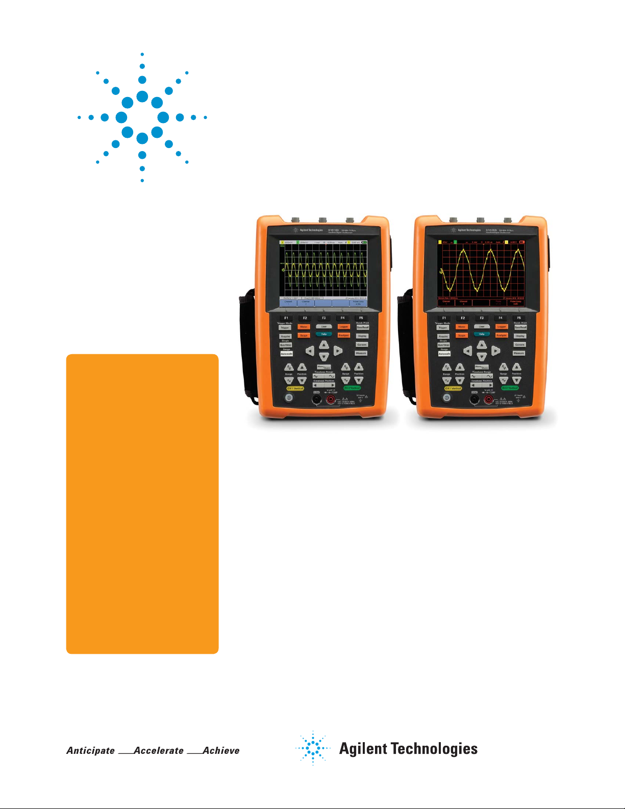
Agilent U1610A/U1620A Handheld
Features
Digital Oscilloscope
Data Sheet
• 100/200 MHz bandwidth with
two isolated channels
• 5.7-inch VGA TFT LCD display
with 3 selectable viewing
modes (indoor, outdoor and
night vision)
• 2 Mpts memory depth and
2 GSa/s sampling rate allows
detailed analysis of captured
glitches
• 10,000-count resolution on
DMM display
• Channel-to-channel isolation
with CAT III 600 V safety
ratings
• Data logging capability to PC
• 10 selectable languages on
the User Interface (UI) system
Night vision viewing modeIndoor viewing mode
Retool your expectations in the world’s first VGA
display handheld oscilloscope with two isolated
channels
The U1610A/U1620A is the world’s first handheld oscilloscope with a VGA
display. This 100/200 MHz handheld oscilloscope offers a floating measurement
capability with two CAT III 600 V isolated channels. With up to 2 GSa/s sampling rate and 2 Mpts memory depth, it captures more waveforms from signals
such as pulse width modulated circuit, in rush, transient, and motor start up
sequences. The benchtop-like display and dual window zoom allow you to easily
identify problem areas and zoom in for more detailed analysis. Now, you can
view signals in detail and detect glitches easily.
Page 2

5.7-inch VGA display with 3 selectable viewing modes
Visualizing electrical waveforms has never been in such clarity. Our U1610A/U1620A oscilloscope comes with a 5.7-inch
VGA TFT LCD display that enables clear viewing of measurements on-site and on the field. With the option of up to three
viewing modes, users can now view waveforms under all lighting conditions, including in indoor, outdoor or dark environments. All three viewing modes have predefined contrast levels for customized lighting conditions and optimized battery
life.
Indoor mode
The indoor mode has high contrast
and brightness levels to clearly
distinguish waveforms under an
indoor light environment. Engineered
with a VGA TFT LCD screen, users
can now view the display across wide
viewing angles for more efficient
troubleshooting task.
Figure 1. Indoor mode for clear
distinct readings
Outdoor mode
When performing field work in an
outdoor environment, users can easily
switch to this viewing mode via a set
of accessible soft keys. This mode
works in an anti-glare mechanism; it
filters out excessive sunlight, hence
reducing the risk of misreading or
misinterpreting measurements.
Figure 2. Outdoor mode that is
sunlight viewable
Night vision mode
The night vision mode is tailored to
be viewable under subdued lighting
by enabling high contrast levels
between the screen background and
waveforms. With a single press of
button, this mode is activated and
the screen automatically adjusts with
proper colour correction-creating
clear contrasts between the waveforms against the dark environment.
This mode is useful when measuring
high speed signals, particularly in
non-repetitive signals.
Figure 3. Night vision mode for
performing tasks in a poorly lit
environment
2 Mpts memory depth and 2 GSa/s sampling rate allows detailed analysis of
captured glitches
A good oscilloscope must be accompanied with even better specifications for an in-depth analysis of captured glitches.
With deep memory of 2 Mpts and sampling rate of 2 GSa/s, non-repeating signals can be captured over a wider time
base. What’s more, its dual window zoom feature allows you to work more productively by simultaneously viewing signals
captured over a period of time and zooming into the most subtle details.
Channel-to-channel isolation with CAT III 600 V safety ratings
The U1610/U1620A extends the maximum input rating to cater for high voltage measurement and transient voltages which
are recordable via a handheld oscilloscope. Equipped with the most robust isolation topology, technicians can now measure signals in the field and perform floating measurements. This type of isolation enables each channel to be individually
isolated from one another and from other non-isolated system components.
Up to 10 selectable languages programmed in the scope
The U1610A/U1620A is programmed with up to 10 selectable languages (English, French, German, Italian, Spanish,
Portuguese, Traditional and Simplified Chinese, Japanese and Korean) on the User Interface (UI) system and help menu.
The diverse range of languages offered here gives users the choice to operate the unit in the language that they are most
comfortable in.
2
Page 3
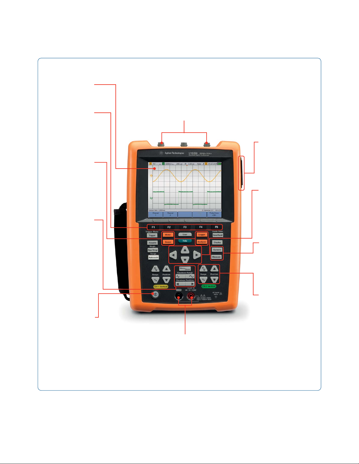
Front panel description
5.7- inch VGA
color display
Function softkeys
To perform
functions displayed
above each softkey
Acquisition and
function controls
To access the
scope, meter,
logger, system
functions
Horizontal
controls
To control the
sweep speed
(sec/div) and
horizontal position
of the waveform.
Use Menu/Zoom
to zoom into
waveforms
Scope terminals
USB interface
connector and DC
power inlet
Directional keys
Measurement
softkeys
To make quick
measurements and
place cursors on the
waveform
Power on/off
button
Vertical controls
To set the vertical
scaling (volt/div)
and vertical offset
Meter terminals
Outdoor viewing mode as illustrated
Figure 4. The U1620A as shown
3
Page 4

Specifications
U1610A U1620A
Specification
Vertical system
Bandwidth (-3 dB)
DC vertical gain accuracy
Dual cursor accuracy
Characteristic
Acquisition
Maximum Sampling Rate
Single Chanel Operation 1 GSa/s interleave 2 GSa/s interleave
Dual Channel Operation 500 MS/s each channel 1 GS/s each channel
Maximum Recording Length
Single Chanel Operation 120 Kpts interleave 2 Mpts interleave
Dual Channel Operation 60 Kpts each channel 1 Mpts each channel
Vertical resolution 8 bits
Peak detection > 10 ns > 5 ns
Average Selectable from 2 to 8192 in powers-of-2 increments
Filter 10 kHz and 20 MHz bandwidth limiters
Interpolation (Sin x)/x
Vertical system
Analog channels Channel 1 and Channel 2 simultaneous acquisition
Calculated rise time 3.50 ns typical 1.75 ns typical
Vertical scale 2 mV/div to 50 V/div
Maximum input CAT III 600 Vrms (with 10:1 probe)
Offset (position) range ± 4 div
Dynamic range ± 8 div
Input impedance 1 MΩ ± 1% ≈ 22 pF ± 3 Pf
Coupling DC, AC
Bandwidth limit 10 kHz and 20 MHz (selectable)
Channel-to-channel isolation
(with channels at the same V/div)
Probes U1560-60002 1:1 passive probe
Probe attenuation factors 1x, 10x, 100x
Probe compensation output 5 V
Noise peak-to-peak (typical) 3% of full scale or 5 mV
DC vertical offset (position) accuracy ± 0.1 div ± 2 mV ±1.6% offset value
Single cursor accuracy ± {DC vertical gain accuracy + DC vertical offset accuracy + 0.2% full scale (~½ least
1
1
1
± {DC vertical gain accuracy + 0.4% full scale (~1 least significant bit (LSB)}
!
100 MHz 200 MHz
± 4% of full scale
Full scale is equivalent to 8 div
± {4% full scale ± 0.4% full scale (~1 LSB)}
CAT III 300 Vrms (direct / 1:1 probe)
CAT III 600 Vrms
!
U1561-60002 10:1 passive probe
U1562-60002 100:1 passive probe
, 1 kHz
pp
, whichever greater
pp
significant bit (LSB)}
± {4% full scale ± 0.1 div ± 2 mV ± 1.6% offset value + 0.2% full scale (~½ LSB)}
4
Page 5

Specifications (continued)
U1610A U1620A
Characteristic (continued)
Horizontal system
Range 5 ns/div to 50 s/div 2 ns/div to 50 s/div
Resolution 100 ps for 5 ns/div 40 ps for 2 ns/div
Timebase accuracy 25 ppm
Reference position Left, center, right
Delay range (pre-trigger) 1 screen width or 120 µs (whichever less) 1 screen width or 1 ms (whichever less)
Delay range (post-trigger) 50 ms to 500 s 20 ms to 500 s
Delay resolution 100 ps for 5 ns/div 40 ps for 2 ns/div
Delay time measurement accuracy Same channel: ± 0.0025% reading ± 0.17% screen width ± 60 ps
Channel-to-channel: ± 0.0025% reading ± 0.17% screen width ± 120 ps
Modes Main, zoom, XY, roll
Horizontal pan and zoom Dual window zoom
Trigger system
Sources Channel 1, Channel 2, External
Modes Normal, Single, Auto
Types Edge, Glitch, TV, Nth Edge, CAN, LIN
Autoscale Finds or displays active channels, sets the edge trigger type on the highest numbered
channel, and sets the vertical sensitivity on the scope channel timebase to display
~2 periods
Requires > 10 mV
Holdoff time 60 ns to 10 s
Range ± 6 div from center of screen
Sensitivity ≥ 10 mV/div: 0.5 div
Trigger level accuracy ± 0.6 div
Coupling modes AC (~10 Hz), DC, LF-Reject (~35 kHz), HF-Reject (~35 kHz)
External trigger
• Input impedance 1 MΩ ≈ 10 pF
• Maximum input CAT III 300 Vrms
!
• Range DC coupling: trigger level ± 5 V
• Bandwidth 100 kHz
Measurement
Automatic measurements Delay, duty cycle (+/–), fall/rise time, frequency, period, phase shift, T-max, T-min, width
(+/–), amplitude, average, base, crest, cycle mean, maximum, minimum, overshoot,
peak-to-peak, preshoot, standard deviation, top, Vrms (AC/DC), active/apparent/reactive
Waveform math functions CH1 + CH2, CH1 – CH2, CH2 – CH1, CH1 × CH2, CH1/CH2, CH2/CH1, d/dt (CH1), d/dt
Cursors Delta V: Voltage difference between cursors
FFT points 1024
FFT windows Rectangular, Hamming, Hanning, Blackman-Harris, Flattop
minimum voltage, 0.5% duty cycle, and > 50 Hz minimum frequency
pp
< 10 mV/div: greater of 1 div or 5 mV
power, power factor
(CH2), ∫(CH1)dt, ∫(CH2)dt, FFT
Delta T: Time difference between cursors
5
Page 6

Specifications (continued)
U1610A U1620A
Characteristic (continued)
Display system
Display 5.7" TFT LCD VGA Color (outdoor readable)
Resolution VGA (screen area): 640 vertical by 480 horizontal
Control Vectors on/off, sin x/x interpolation on/off, infinite persistence on/off, backlight
intensity, color scheme, clear display
Real-time clock Date and time (adjustable)
Language 10 languages (selectable)
Built-in help system Functional quick help displayed by pressing the [Help] button
Storage system
Save/recall (non-volatile) 10 setups and waveforms can be saved and recalled internally
Storage mode USB 2.0 full speed host port (Support up to 4GB USB drive)
Image formats: .bmp (8-bit, 24-bit) and .png (24-bit)
Data format: .csv
I/O USB 2.0 full-speed host, USB 2.0 full-speed client
Printer compatibility PCL Inkjet, PCL Laser
1. Denotes warranted specifications, all others are typical. Specifications are valid after a 30-minute warm-up period and within 23 ± 10 °C of last
calibration temperature.
6
Page 7
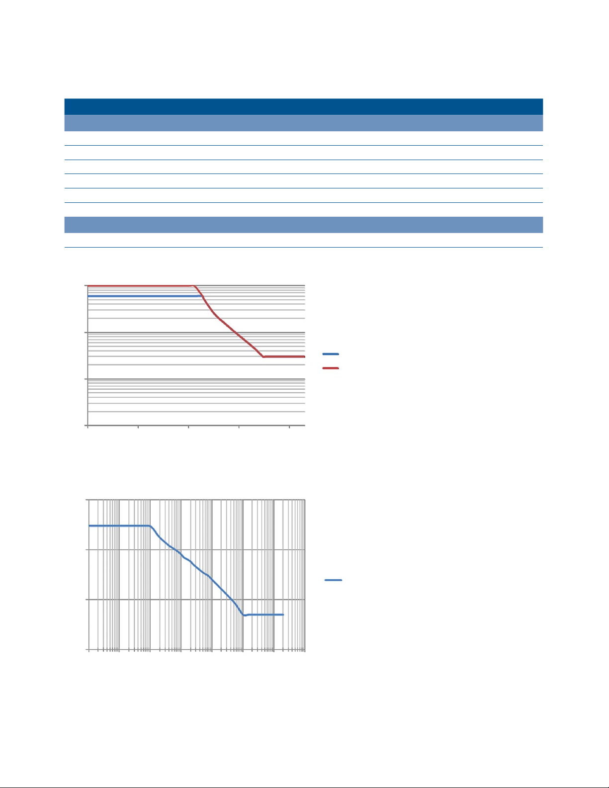
Maximum input voltages and channel isolation
U1610A and U1620A
Maximum input voltages
Input CH1 and CH2 direct (1:1 probe) 300 Vrms CAT III
1
Input CH1 and CH2 (1:10 probe) 600 Vrms
1
Input CH1 and CH2 (1:100 probe) 600 Vrms
Meter input 600 Vrms CAT III, 1000 Vrms CAT II
Scope input 300 Vrms CAT III
Voltage ratings Vrms 50–60 Hz (AC sine wave), VDC (DC applications)
CAT II, 1000 Vrms1 CAT II, 3540 Vrms1 CAT I
Channel isolation
From any terminal to earth ground 600 Vrms CAT III
1. Refer to the respective probe's manual for more information on the specification
1000
100
CAT III, 1000 Vrms1 CAT II
10
1
0.01 0.1 1 10 100
Figure 5. Maximum safety voltage for scope reference to earth
1000
100
10
CAT lll 600
CAT ll 1000
Max input voltage
1
0.0001 0.001 0.01 0.1 1 10 100 1000
Figure 6. Maximum input voltage
7
Page 8

Digital multimeter specifications
• Accuracy is given as ± (% of reading + counts of least significant digit) at 23 °C ± 5 °C, with relative humidity < 80 RH.
• AC V specifications are AC coupled, true RMS and are valid from 5% to 100% of range.
Maximum reading 10,000 counts with automatic polarity indication
Voltage CAT II 1000 V or CAT III 600 V
Function Range Resolution Accuracy Input impedance
(nominal)
DCV 1000.0 mV 0.1 mV 0.09% + 5 11.11 MΩ
10.000 V 0.001 V
100.00 V 0.01 V
2
0.1 V 0.15% + 5
0.001 V
0.01V
2
0.1 V
0.001 V
0.01 V
2
0.1 V
1 V 0.001 V 0.3% + 2 ~0.5 mA
ACV
ACV + DCV
3
Diode
1000.0 V
1000.0 mV 0.1 mV
10.000 V
100.00 V
1000.0 V
1000.0 mV 0.1 mV
10.000 V
100.00 V
1000.00 V
Beeper < ~50 mV, Single tone for normal forward-biased diode or semiconductor junction of
Instant continuity
Resistance 1000.00 Ω
3
10.000 kΩ
4
4
0.1 Ω
0.001 kΩ 50 µA
100.00 kΩ 0.01 kΩ 4.91 µA
1000.0 kΩ 0.1 kΩ 447 nA
10.000 MΩ 0.001 MΩ 0.8% + 3 112 nA
100.00 MΩ
5
0.01 MΩ 1.5% + 3 112 nA
Capacitance 1000.0 nF 0.1 nF
10.000 μF 0.001 μF
100.00 μF 0.01 μF
1000.0 μF 0.1 μF
10.000 mF 0.001 mF
0.09% + 2
1% + 5 (40 to 500 Hz)
2% + 5 (500 Hz to 1 kHz)
1% + 5 (40 to 500 Hz)
1% + 5 (500 Hz to 1 kHz)
2% + 5 (1 to 2 kHz)
1% + 5 (40 to 500 Hz)
1% + 5 (500 Hz to 1 kHz)
1.1% + 10 (40 to 500 Hz)
2.1% + 10 (500 Hz to 1 kHz)
1.1% + 7 (40 to 500 Hz)
1.1% + 7 (500 Hz to 1 kHz)
2% + 5 (1 to 2 kHz)
1.2% + 10 (40 to 500 Hz)
1.2% + 10 (500 Hz to 1 kHz)
0.3 V ≤ reading ≤ 0.8 V
8
Continuous beep when resistance < 10 Ω
0.3% + 3
2% + 4
6
6
1.2% + 4
10.10 MΩ
10.01 MΩ
10.00 MΩ
10.00 MΩ
8
Test current
0.5 mA
8
Page 9

Digital multimeter specifications (continued)
Maximum
10,000 counts with automatic polarity indication
reading
Voltage
Function Range Resolution Accuracy Input impedance
Temperature
Frequency
1. Only allowed to measure up to CAT III 600 V if referring to GND.
2. Only allowed for floating voltage.
3. Denotes typical specifications, all others are warranted.
4. The accuracy is specified after the Null function is used to subtract the test lead resistance and thermal effect.
5. RH is specified for < 60%. The temperature coefficient is 0.15 × specified accuracy as > 50 MΩ.
6. The accuracy is based on film capacitors or better and uses the Relative mode for residual values.
7. The accuracy is based on using the Null function to reduce the thermal effect.
8. Denotes characteristics.
1
CAT II 1000 V or CAT III 600 V
(nominal)
3
-50 to 1000 °C 1 mV/°C
-50 to -21 °C 2.5% + 2 °C
-20 to 350 °C 0.5% + 2 °C
351 to 500 °C 1.75% + 2 °C
501 to 1000 °C 2% + 2 °C
-58 to -5.8 °F 2.5% + 3.6 °F
-58 to 1832 °F 1 mV/°F
-4 to 662 °F 0.5% + 3.6 °F
664 to 932 °F 1.75% + 3.6 °F
933 to 1832 °F 2% + 3.6 °F
3
100.00 Hz 0.01 Hz
1000.0 Hz 0.1 Hz
10.000 kHz 0.001 kHz
0.03% + 3
100.00 kHz 0.01 kHz
1000.0 kHz 0.1 kHz
7
7
7
7
7
7
7
7
Test current
Data logger specifications
Scope and meter logger
Range 1 s/div – 86400 s/div (1 day/div)
Recording time span 8 days
Memory depth 691200 points
Recording mode Continuous (Range will change according to the time elapsed)
Sampling rate 1 sample/s
9
Page 10

General specifications
Power supply
Power adapter Line voltage range: 50/60 Hz, 100 to 240 VAC, 1.6 A
Output voltage: 15 VDC, 4 A
Installation Category II
Battery Li-Ion rechargeable battery pack, 10.8 V
Operating time: Up to 3 hours
Operating environment
Temperature 0 to 50 °C (with battery only)
0 to 40 °C (with power adapter)
Humidity 0 to 80% RH (0 to 35 °C)
0 to 50% RH (35 to 40/50 °C)
Altitude up to 2000 m
Pollution degree 2
Storage compliance
Temperature -20 to 70 °C
Humidity 0 to 80% RH
Altitude up to 15000 m
Shock Tested to IEC 60068-2-27
Vibration Tested to IEC 60068-2-6, IEC 60068-2-64
Safety compliance IEC 61010-1:2001/EN 61010-1:2001
Canada: CAN/CSA-C22.2 No. 61010-1-04
USA: ANSI/UL 61010-1:2004
EMC compliance IEC 61326-1:2005/EN 61326-1:2006
Australia/New Zealand: AS/NZS CISPR 11:2004
Canada: ICES/NMB-001:ISSUE 4, June 2006
IP rating IP 41 ingress protection according to IEC 60529
Dimensions (W × H × D) 183 x 270 x 65 mm
Weight < 2.5 kg
Warranty 3 years for main unit
3 months for standard shipped accessories unless otherwise stated
10
Page 11
Ordering information
Standard shipped items
• Quick start guide, power adapter, Li-Ion battery pack, USB cable, test lead, 10:1 probe (2 sets), Certificate of Calibration (CoC).
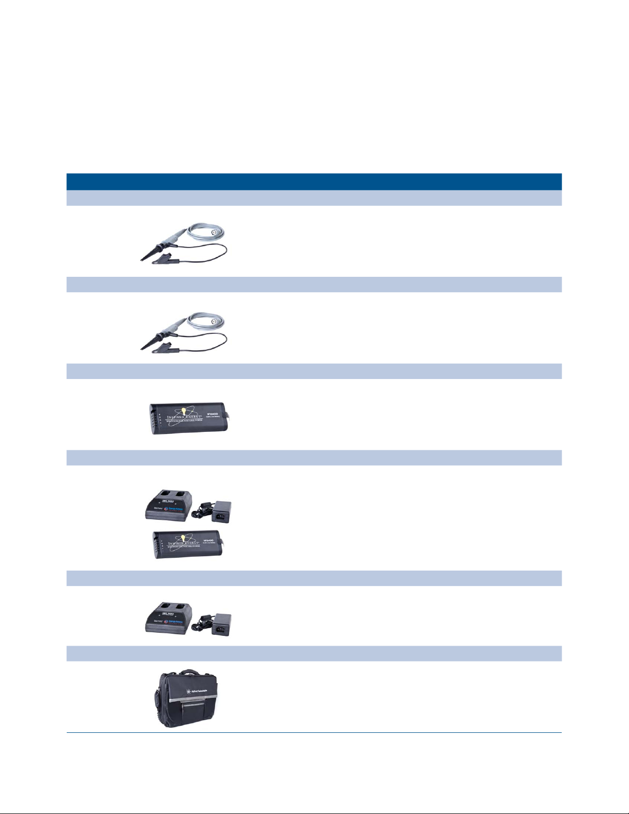
Recommended accessories
Item Description
U1560A
Scope probe x1 CAT III 300 V • Include ground alligator clip and hook clip, rated CAT III 300 V
U1562A
Scope probe x100 CAT III 600 V • Include ground alligator clip and hook clip, rated CAT III 600 V
U1572A
Li Polymer battery pack • 4,800 mAh, 10.8
• Compatible with U1610A/20A handheld oscilloscope
U1573A
Desktop charger & Li Polymer battery pack • 4,800 mAh, 10.8 V
• Compatible with U1610A/20A handheld oscilloscope
U1575A
Desktop charger • 2-output 3 A battery charger
• Dimensions (W x H x D): 4.89 x 2.30 x 6.89 inches
U1591A
Soft carrying case • Soft carrying case with backpack and shoulder strap
• Dimension (W x H x D): 15.7 x 12.6 x 3.9 inches
11
Page 12

www.agilent.com
s
www.agilent.com/find/handheldscope
www.agilent.com/find/U1600
myAgilent
myAgilent
www.agilent.com/find/myagilent
A personalized view into the information
most relevant to you.
www.axiestandard.org
AdvancedTCA® Extensions for
Instrumentation and Test (AXIe) is
an open standard that extends the
AdvancedTCA for general purpose
and semiconductor test. Agilent
is a founding member of the AXIe
consortium.
www.lxistandard.org
LAN eXtensions for Instruments puts
the power of Ethernet and the Web
inside your test systems. Agilent
is a founding member of the LXI
consortium.
www.pxisa.org
PCI eXtensions for Instrumentation
(PXI) modular instrumentation
delivers a rugged, PC-based highperformance measurement and
automation system.
Agilent Channel Partners
www. agilent.com/find/channelpartners
Get the best of both worlds: Agilent’s
measurement expertise and product
breadth, combined with channel
partner convenience.
Agilent Advantage Services is committed
to your success throughout your equipment’s lifetime. To keep you competitive,
we continually invest in tools and
processes that speed up calibration and
repair and reduce your cost of ownership.
You can also use Infoline Web Services
to manage equipment and services more
effectively. By sharing our measurement
and service expertise, we help you create
the products that change our world.
www.agilent.com/find/advantageservices
Agilent Electronic Measurement Group
DEKRA Certified
ISO 9001:2008
Quality Management SystemQuality Management Sy
www.agilent.com/quality
For more information on Agilent
Technologies’ products, applications or
services, please contact your local Agilent
office. The complete list is available at:
www.agilent.com/find/contactus
Americas
Canada (877) 894 4414
Brazil (11) 4197 3600
Mexico 01800 5064 800
United States (800) 829 4444
Asia Pacific
Australia 1 800 629 485
China 800 810 0189
Hong Kong 800 938 693
India 1 800 112 929
Japan 0120 (421) 345
Korea 080 769 0800
Malaysia 1 800 888 848
Singapore 1 800 375 8100
Taiwan 0800 047 866
Other AP Countries (65) 375 8100
Europe & Middle East
Belgium 32 (0) 2 404 93 40
Denmark 45 45 80 12 15
Finland 358 (0) 10 855 2100
France 0825 010 700*
*0.125 €/minute
Germany 49 (0) 7031 464 6333
Ireland 1890 924 204
Israel 972-3-9288-504/544
Italy 39 02 92 60 8484
Netherlands 31 (0) 20 547 2111
Spain 34 (91) 631 3300
Sweden 0200-88 22 55
United Kingdom 44 (0) 118 927 6201
For other unlisted countries:
www.agilent.com/find/contactus
Revised: October 11, 2012
Product specifications and descriptions
in this document subject to change
without notice.
© Agilent Technologies, Inc. 2013
Published in USA, February 6, 2013
5990-9523EN
 Loading...