

Page 1
Agilent
4-Port PNA-L Microwave
Network Analyzer
N5230A
300 kHz to 13.5, 20 GHz
Data Sheet
Please note: This document does not contain Agilent’s
most up-to-date PNA-L network analyzer portfolio. This
document is available for reference only for customers
using Agilent’s legacy network analyzers. To view the
current Agilent 4-port PNA-L Microwave Network
Analyzer Data Sheet click here.
Note:
Specification information in
this document is also available
within the PNA-L network analyzer’s internal Help system.
Page 2

Table of Contents
Definitions . . . . . . . . . . . . . . . . . . . . . . . . . . . . . . . . . . . . . . . . . . . . . . . . . . . . . . 3
Corrected System Performance . . . . . . . . . . . . . . . . . . . . . . . . . . . . . . . . . . . . . 4
Table 1. System dynamic range . . . . . . . . . . . . . . . . . . . . . . . . . . . . . . . . . . . . . . . . . . 4
Table 2. Extended dynamic range . . . . . . . . . . . . . . . . . . . . . . . . . . . . . . . . . . . . . . . . . 5
N5230A Option 140/145/146/240/245/246
Corrected system performance with 3.5mm connectors . . . . . . . . . . . . . . . . . . . . 6
Table 3. 85052B Calibration kit N5230A
Option 140/145/146/240/245/246 . . . . . . . . . . . . . . . . . . . . . . . . . . . . . . . . . . . . . .6
Table 4. N4433A Electronic calibration module N5230A
Option 140/145/146/240/245/246 . . . . . . . . . . . . . . . . . . . . . . . . . . . . . . . . . . . . . 8
Table 5. Uncorrected system performance . . . . . . . . . . . . . . . . . . . . . . . . . . . . . . . . 10
Table 6. Test port output . . . . . . . . . . . . . . . . . . . . . . . . . . . . . . . . . . . . . . . . . . . . . . . 11
Table 7: Test port input . . . . . . . . . . . . . . . . . . . . . . . . . . . . . . . . . . . . . . . . . . . . . . . . 13
Table 8. Dynamic accuracy . . . . . . . . . . . . . . . . . . . . . . . . . . . . . . . . . . . . . . . . . . . . . .16
Table 9. Test port input (group delay) . . . . . . . . . . . . . . . . . . . . . . . . . . . . . . . . . . . . 22
General Information . . . . . . . . . . . . . . . . . . . . . . . . . . . . . . . . . . . . . . . . . . . . . . 23
Table 10. Miscellaneous information . . . . . . . . . . . . . . . . . . . . . . . . . . . . . . . . . . . . . 23
Table 11. Front panel information . . . . . . . . . . . . . . . . . . . . . . . . . . . . . . . . . . . . . . . . 23
Table 12. Rear panel information . . . . . . . . . . . . . . . . . . . . . . . . . . . . . . . . . . . . . . . . 24
Table 13. Analyzer environment and dimensions . . . . . . . . . . . . . . . . . . . . . . . . . . . 25
Measurement Throughput Summary . . . . . . . . . . . . . . . . . . . . . . . . . . . . . . . . 26
Table 14. Typical cycle time (ms) for measurement completion . . . . . . . . . . . . . . . .26
Table 15. Cycle time vs IF bandwidth . . . . . . . . . . . . . . . . . . . . . . . . . . . . . . . . . . . . . .27
Table 16. Cycle time vs number of points . . . . . . . . . . . . . . . . . . . . . . . . . . . . . . . . . .28
Table 17. Data transfer time (ms) . . . . . . . . . . . . . . . . . . . . . . . . . . . . . . . . . . . . . . . . .28
Specifications: Front-Panel Jumpers . . . . . . . . . . . . . . . . . . . . . . . . . . . . . . . . 29
Table 18: Measurement receiver inputs, 0.1 dB typical compression . . . . . . . . . . . 29
Table 19: Reference receiver input at max. specified output power . . . . . . . . . . . . 29
Table 20: Reference output at max. specified output power . . . . . . . . . . . . . . . . . . 29
Table 21: Source outputs at max. specified output power . . . . . . . . . . . . . . . . . . . . 30
Table 22: Coupler inputs, insertion loss of coupler thru . . . . . . . . . . . . . . . . . . . . . . 30
Table 23: Coupler outputs . . . . . . . . . . . . . . . . . . . . . . . . . . . . . . . . . . . . . . . . . . . . . . 30
Test Set Block Diagrams . . . . . . . . . . . . . . . . . . . . . . . . . . . . . . . . . . . . . . . . . . 31
N5230A Option 140 or 240
(standard test set and standard power range) network analyzer . . . . . . . . . . . . 31
N5230A Option 145 or 245
(configurable test set and extended power range) network analyzer . . . . . . . . . . . 31
N5230A Option 146 or 246
(configurable test set, extended power range, and internal second
source) network analyzer . . . . . . . . . . . . . . . . . . . . . . . . . . . . . . . . . . . . . . . . . . . . . 31
Web Resources . . . . . . . . . . . . . . . . . . . . . . . . . . . . . . . . . . . . . . . . . . . . . . . . . 32
2
Page 3

This is a subset of technical specifications for the N5230A Options 140, 145, 146, 240, 245,
and 246 network analyzers.
• Option 140, 300 kHz to 13.5 GHz, 4-port with standard test set and standard power
range
• Option 145, 300 kHz to 13.5 GHz, 4-port with configurable test set and extended power
range
• Option 146, 300 kHz to 13.5 GHz, 4-port with configurable test set and extended power
range with internal second source
• Option 240, 300 kHz to 20 GHz, 4-port with standard test set and standard power range
• Option 245, 300 kHz to 20 GHz, 4-port with configurable test set and extended power
range
• Option 246, 300 kHz to 20 GHz, 4-port with configurable test set and extended power
range with internal second source
To view or print the N5230A technical specifications, visit our web site at
www.agilent.com/find/pnal
This N5230A document provides technical specifications for the following calibration
kit and ECal module only: 85052B and N4433A. Please download our free Uncertainty
Calculator from www.agilent.com/find/na_calculator to generate the curves for
your calibration kit and PNA setup.
Definitions
All specifications and characteristics apply over a 25 °C ±5 °C range
(unless otherwise stated) and 90 minutes after the instrument has been turned on.
Specification (spec.): Warranted performance. Specifications include
guardbands to account for the expected statistical performance distribution, measurement
uncertainties, and changes in performance due to
environmental conditions.
Characteristic (char.): A performance parameter that the product is expected
to meet before it leaves the factory, but that is not verified in the field and is not covered
by the product warranty. A characteristic includes the same guardbands as a specification.
Typical (typ.): Expected performance of an average unit which does not include guardbands. It is not covered by the product warranty.
Nominal (nom.): A general, descriptive term that does not imply a level of
performance. It is not covered by the product warranty.
Calibration: The process of measuring known standards to characterize a
network analyzer's systematic (repeatable) errors.
Corrected (residual): Indicates performance after error correction (calibration). It is determined by the quality of calibration standards and how well "known" they are, plus system
repeatability, stability, and noise.
Uncorrected (raw): Indicates instrument performance without error correction. The uncorrected performance affects the stability of a calibration.
Standard: When referring to the analyzer, this includes no options unless
noted otherwise.
3
Page 4

Corrected System Performance
The specifications in this section apply for measurements made with the N5230A Options
140, 145, 146, 240, 245, and 246 analyzers with the following conditions:
• 10 Hz IF bandwidth
• No averaging applied to data
• Isolation calibration with an averaging factor of 8
Table 1. System dynamic range at test port
1
Standard configuration and standard power range (Options 140, 240)
Description
at test port at test port
300 kHz to 10 MHz
10 MHz to 4 GHz
4 to 6 GHz 118 129
6 to 10.5 GHz 115 127
10.5 to 13.5 GHz 107 119
13.5 to 15 GHz 107 119
15 to 20 GHz 103 116
Specification (dB) Typical (dB)
2
111
2
120 128
Configurable test set and extended power range (Options 145, 245)
Configurable test set, extended power range, and internal second source
(Options 146, 246)
Description
at test port at test port
300 kHz to 10 MHz
10 MHz to 4 GHz
4 to 6 GHz 118 128
6 to 10.5 GHz 113 125
10.5 to 13.5 GHz 105 117
13.5 to 15 GHz 105 11
15 to 20 GHz 98 115
1. The system dynamic range is calculated as the difference between the noise floor and the specified
source maximum output power. The effective dynamic range must take measurement uncertainties
and interfering signals into account.
2. May be degraded by 10 dB at particular frequencies (multiples of 5 MHz) below 500 MHz due to
spurious receiver residuals. Methods are available to regain the full dynamic range.
Specification (dB) Typical (dB)
2
111
2
120 128
4
Page 5

Table 2. Extended dynamic range
1
Configurable test set and extended power range (Options 145, 245)
Configurable test set, extended power range, and internal second source
(Options 146, 246)
Specification (dB) at Typical (dB) at
Description direct receiver direct receiver
access input access input
300 kHz to 10 MHz
10 MHz to 4 GHz
4 to 6 GHz 134
6 to 10.5 GHz 129
10.5 to 13.5 GHz 121
13.5 to 15 GHz 121
15 to 20 GHz 114
1. The direct receiver access input extended dynamic range is calculated as the difference between
the direct receiver access input noise floor and the source maximum output power. The effective
dynamic range must take measurement uncertainties and interfering signals into account. This
setup should only be used when the receiver input will never exceed its compression or damage
level. When the analyzer is in segment sweep mode, it can have predefined frequency segments
which will output a higher power level when the extended dynamic range is required (i.e. devices
with high insertion loss), and reduced power when receiver compression or damage may
occur (i.e. devices with low insertion loss). The extended range is only available in one-path
transmission measurements.
2. May be degraded by 10 dB at particular frequencies (multiples of 5 MHz) below 500 MHz due to
spurious receiver residuals. Methods are available to regain the full dynamic range.
2
124
2
136
5
Page 6
N5230A Option 140/145/146/240/245/246
Corrected system performance with 3.5 mm connectors
1
Note: For any Sii reflection measurement:
S
For any S
S
S
S
Table 3. 85052B Calibration kit
= 0
jj
transmission measurement:
ij
when S
when S
ij
for all k
≤ 1
ij
≥ 1
ij
ji = Sij
1/S
ji =
kk = 0
N5230A
• Option 140 or 240 standard test set and standard power range
• Option 145 or 245 configurable test set and extended power range
• Option 146 or 246 configurable test set and extended power range with internal
second source
Applies to the N5230A Option 140/145/146/240/245/246 analyzers, 85052B (3.5mm)
calibration kit, 85131F flexible test port cable set, and a full 4-port calibration. Also applies
to the following condition: Environmental temperature 23° ±3 °C, with < 1 °C deviation
from calibration temperature.
Specification (dB)
Description
500 MHz 2 GHz 8 GHz 13.5 GHz 20 GHz
10 to 500 MHz to 2 to 8 to 13.5 to
Directivity 48 48 44 44 44
Source match 40 40 33 31 31
Load match 48 48 44 44 44
Reflection ±0.003 ±0.003 ±0.003 ±0.006 ±0.006
tracking (+0.01/°C) (+0.01/°C) (+0.02/°C) (+0.03/°C) (+0.03/°C)
Transmission ±0.017 ±0.017 ±0.062 ±0.125 ±0.125
tracking (+0.01/°C) (+0.01/°C) (+0.02/°C) (+0.03/°C) (+0.03/°C)
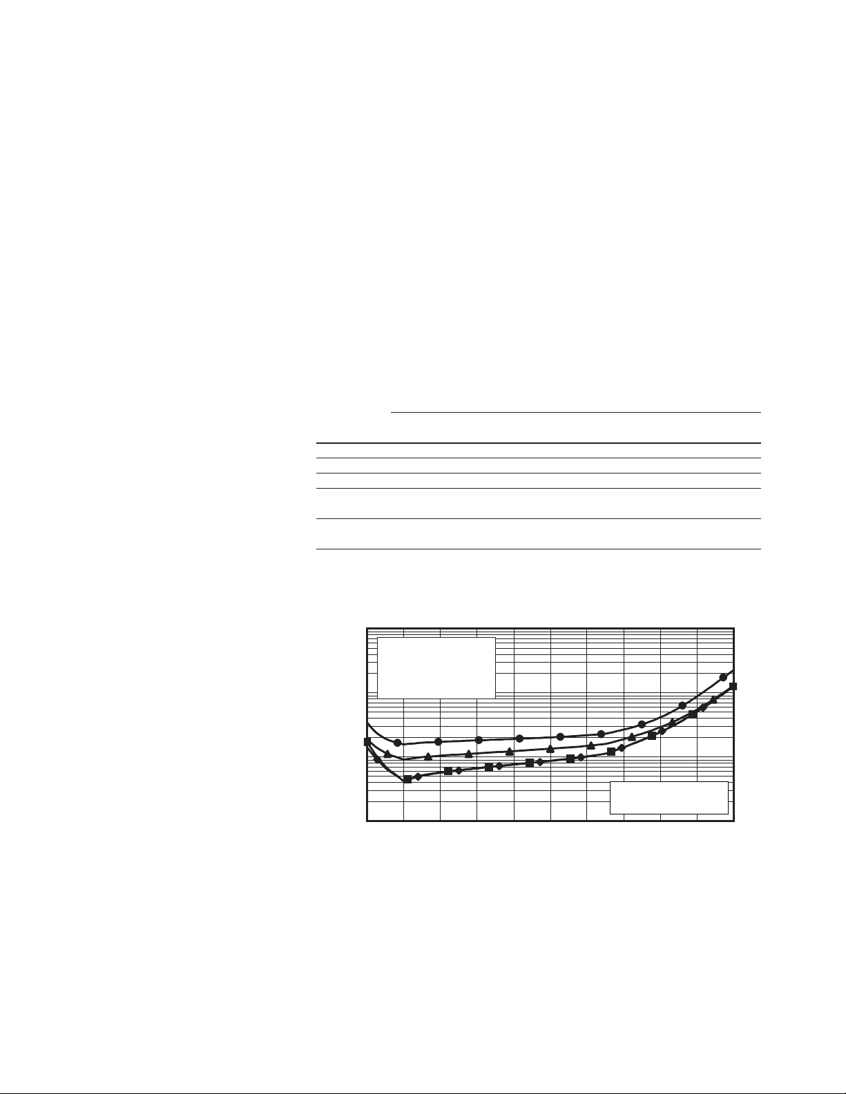
Transmission uncertainty (specifications)
Magnitude
10
1
0.1
Uncertainty (dB)
0.01
N5230A Option 140/145/146/240/245/246 with 85052B
■
10 to 500 MHz
♦
500 MHz to 2 GHz
▲
2 to 8 GHz
●
8 to 20 GHz
S11 = S22 = 0
Source power = -5 dBm
Transmission coefficient (dB)
-90-80-70-60-50-40-30-20-10010
1. From 300 kHz to 10 MHz, performance is characterized as “typical”. To generate these typical values,
please download our free Uncertainty Calculator from
www.agilent.com/find/na_calculator.
6
Page 7
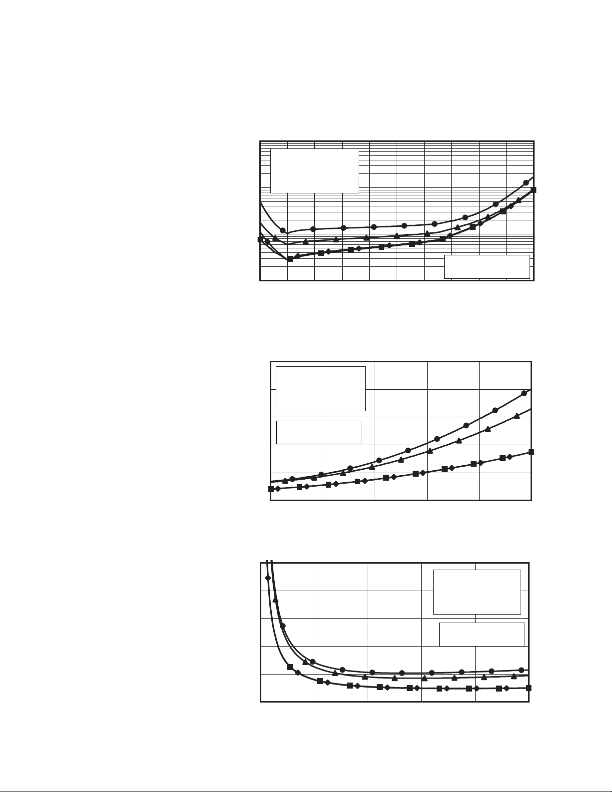
Table 3. 85052B Calibration kit (continued)
N5230A
• Option 140 or 240 standard test set and standard power range
• Option 145 or 245 configurable test set and extended power range
• Option 146 or 246 configurable test set and extended power range with internal
second source
Phase
100
10
1
N5230A Option 140/145/146/240/245/246 with 85052B
■
10 to 500 MHz
♦ 500 MHz to 2 GHz
▲ 2 to 8 GHz
● 8 to 20 GHz
Uncertainty (degrees)
0.1
Transmission coefficient (dB)
Reflection uncertainty (specifications)
Magnitude
0.05
0.04
0.03
0.02
Uncertainty (linear)
0.01
0
0 0.2 0.4 0.6 0.8 1
N5230A Option 140/145/146/240/245/246 with 85052B
■
10 to 500 MHz
♦
500 MHz to 2 GHz
▲
2 to 8 GHz
●
8 to 20 GHz
S21 = S12 = 0
Source power = -5 dBm
Reflection coefficient (linear)
S11 = S22 = 0
Source power = -5 dBm
-90-80-70-60-50-40-30-20-10010
Phase
10
8
6
4
Uncertainty (deg)
2
0
0 0.2 0.4 0.6 0.8 1
N5230A Option 140/145/146/240/245/246 with 85052B
■
10 to 500 MHz
♦
500 MHz to 2 GHz
▲
2 to 8 GHz
●
8 to 20 GHz
S21 = S12 = 0
Source power = -5 dBm
Reflection coefficient (linear)
7
Page 8
N5230A Option 140/145/146/240/245/246
Corrected system performance with 3.5 mm connectors
Table 4. N4433A Electronic calibration module
N5230A
• Option 140 or 240 standard test set and standard power range
• Option 145 or 245 configurable test set and extended power range
• Option 146 or 246 configurable test set and extended power range with internal
second source
Applies to the N5230A Option 140/145/146/240/245/246 analyzers, N4433A
electronic calibration module, 85131F flexible test port cable set, and a full 4-port calibration.
Also applies to the following condition:
Environmental temperature 23° ±3 °C, with < 1 °C deviation from calibration temperature.
Specification (dB)
Description
500 MHz 2 GHz 8 GHz 13.5 GHz 20 GHz
Directivity 52 52 47 45 45
Source match 42 42 39 31 31
Load match 45 45 41 35 35
Reflection ±0.060 ±0.060 ±0.090 ±0.040 ±0.180
tracking (+0.01/°C) (+0.01/°C) (+0.02/°C) (+0.03/°C) (+0.03/°C)
Transmission ±0.045 ±0.039 ±0.055 ±0.127 ±0.160
tracking (+0.01/°C) (+0.01/°C) (+0.02/°C) (+0.03/°C) (+0.03/°C)
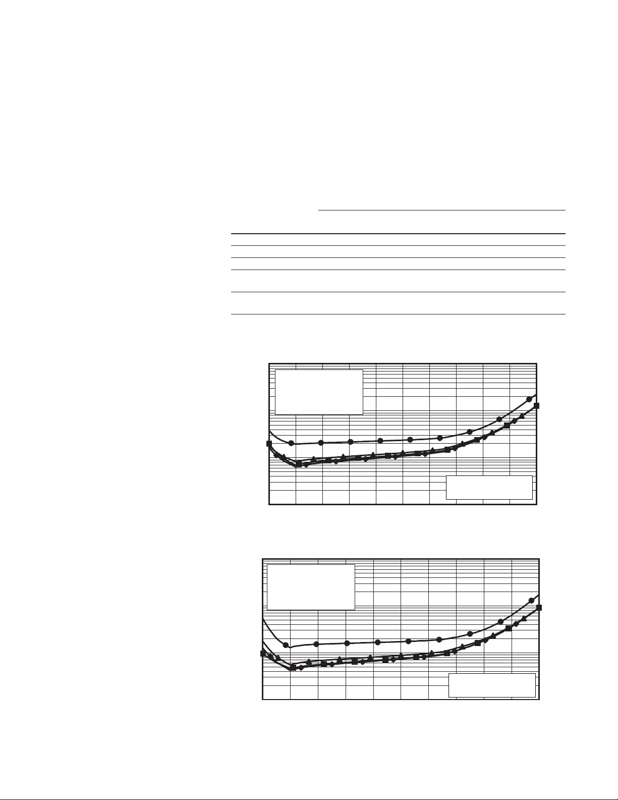
Transmission uncertainty (specifications)
Magnitude
10 to 500 MHz to 2 to 8 to 13.5 to
N5230A Option 140/145/146/240/245/246 full 2-port2 cal using N4433A
10
■
10 to 500 MHz
♦
500 MHz to 2 GHz
▲
2 to 8 GHz
●
1
8 to 20 GHz
1
(continued)
0.1
Uncertainty (dB)
S11 = S22 = 0
Source power = -5 dBm
0.01
-90-80-70-60-50-40-30-20-10010
Transmission coefficient (dB)
Phase
N5230A Option 140/145/146/240/245/246 full 2-port2 cal using N4433A
100
■
10 to 500 MHz
♦
500 MHz to 2 GHz
▲
2 to 8 GHz
●
10
Uncertainty (degrees)
0.1
8
1. From 300 kHz to 10 MHz, performance is characterized as “typical”. To generate these typical values,
please download our free Uncertainty Calculator from
2. All of the curves are for 2-port calibrations. Multiport uncertainties are currently not supported.
8 to 20 GHz
1
S11 = S22 = 0
Source power = -5 dBm
-90-80-70-60-50-40-30-20-10010
Transmission coefficient (dB)
www.agilent.com/find/na_calculator.
Page 9
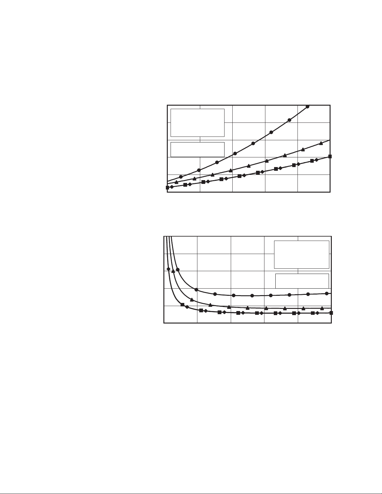
Table 4. N4433A Electronic calibration module (continued)
N5230A
• Option 140 or 240 standard test set and standard power range
• Option 145 or 245 configurable test set and extended power range
• Option 146 or 246 configurable test set and extended power range with internal
second source
Reflection uncertainty (specifications)
Magnitude
0.05
■
10 to 500 MHz
♦
0.04
500 MHz to 2 GHz
▲
●
8 to 20 GHz
0.03
S21 = S12 = 0
0.02
0.01
Uncertainty (linear)
Source power = -5 dBm
0
0 0.2 0.4 0.6 0.8 1
Phase
10
8
6
4
N5230A Option 140/145/146/240/245/246 with N4433A
2 to 8 GHz
Reflection coefficient (linear)
N5230A Option 140/145/146/240/245/246 with N4433A
■
10 to 500 MHz
♦
500 MHz to 2 GHz
▲
2 to 8 GHz
●
8 to 20 GHz
S21 = S12 = 0
Source power = -5 dBm
2
Uncertainty (deg)
0
0 0.2 0.4 0.6 0.8 1
Reflection coefficient (linear)
9
Page 10

Table 5. Uncorrected system performance
Directivity
Options 140, 145, 146, Options 140, 145, 146,
Specifications Typicals
1
240, 245, 246 240, 245,246
300 kHz to 10 MHz –23 dB
10 MHz to 1 GHz –28 dB
1 to 3 GHz –25 dB
3 to 5 GHz –20 dB
5 to 11.5 GHz –17 dB
11.5 to 13.5 GHz –15 dB
13.5 to 20 GHz –15 dB
Source match
300 kHz to 10 MHz –8 dB
10 MHz to 1 GHz –12 dB
1 to 3 GHz –12 dB
3 to 5 GHz –12 dB
5 to 10.5 GHz –12 dB
10.5 to 11.5 GHz –10 dB
11.5 to 13.5 GHz –8 dB
13.5 to 20 GHz –8 dB
Load match
300 kHz to 10 MHz –9 dB
10 MHz to 1 GHz –20 dB
1 to 3 GHz –20 dB
3 to 5 GHz –18 dB
5 to 11.5 GHz –12 dB
11.5 to 13.5 GHz –7 dB
13.5 to 16 GHz –7 dB
16 to 20 GHz –7.5 dB
Crosstalk
2
300 kHz to 5 MHz –70 dB
5 to 10 MHz –100 dB
10 to 45 MHz –110 dB
45 MHz to 4 GHz –122 dB
4 to 6 GHz –123 dB
6 to 10.5 GHz –120 dB
10.5 to 13.5 GHz –115 dB
13.5 to 15 GHz –115 dB
15 to 20 GHz –110 dB
1. Specifications apply over environmental temperature of 25 °C ±5 °C with less than 1 °C variation
from calibration temperature.
2. Measurement conditions: normalized to a thru, measured with two shorts, 10 Hz IF bandwidth,
averaging factor of 8, alternate mode source power set to the lesser of the maximum power out
or the maximum receiver power.
10
Page 11

Table 6. Test port output
Description
Options Options Options Options
Specifications Typicals
1
140, 240 145, 146, 245, 246 140, 240 145, 146, 245, 246
Frequency range
Options 140, 145, 146 300 kHz to 13.5 GHz
Options 240, 245, 246 300 kHz to 20 GHz
Nominal power
–5 dBm –8 dBm Preset power; attenuator switch
point 10 dB below nominal power
Frequency resolution
1 Hz
CW accuracy
±1 ppm
Frequency stability
±0.05 ppm. –10° to 70° C
±0.1 ppm/yr maximum
Description
Options Options Options Options
Specifications Typicals
140, 240 145, 146, 245, 246 140, 240 145, 146, 245, 246
Power level accuracy
Variation from nominal power in range 0
300 kHz to 10 MHz ±1.0 dB ±1.0 dB
10 MHz to 2 GHz ±1.0 dB ±1.0 dB
2 to 10.5 GHz ±1.5 dB ±1.5 dB
10.5 to 13.5 GHz ±2.5 dB ±2.5 dB
13.5 to 20 GHz ±2.5 dB ±2.5 dB
Max leveled power
300 kHz to 10 MHz +8 dBm +8 dBm
10 MHz to 4 GHz +8 dBm +8 dBm +12 dBm +11 dBm
4 to 6 GHz +6 dBm +6 dBm +10 dBm +9 dBm
6 to 10.5 GHz +3 dBm +1 dBm +8 dBm +6 dBm
10.5 to 13.5 GHz 0 dBm –2 dBm +5 dBm +3 dBm
13.5 to 15 GHz 0 dBm –2 dBm +5 dBm +3 dBm
15 to 20 GHz –3 dBm –8 dBm +2 dBm –1 dBm
Power level linearity
Specified on Port 1 only. Ports 2, 3, 4 performance is Typical. Test is at the nominal power level.
300 kHz to 10 MHz ±2.0 dB ±2.0 dB
10 MHz to 1 GHz ±2.0 dB ±2.0 dB
1 to 13.5 GHz ±1.5 dB ±1.5 dB
13.5 to 20 GHz ±1.5 dB ±1.5 dB
Power sweep range (ALC)
ALC range starts at maximum-leveled power and decreases by the dB amount specified here.
300 kHz to 10 MHz 35 dB 35 dB
10 MHz to 4 GHz 33 dB 33 dB
4 to 6 GHz 31 dB 31 dB
6 to 10.5 GHz 28 dB 26 dB
10.5 to 13.5 GHz 25 dB 23 dB
13.5 to 15 GHz 25 dB 23 dB
15 to 20 GHz 22 dB 17 dB
Power resolution
0.01 dB 0.01 dB
11
Page 12

Table 6. Test port output1 (Continued)
Description
Options Options Options Options
Specifications Typicals
140, 240 145, 146, 245, 246 140, 240 145, 146, 245, 246
Power range
300 kHz to 10 MHz –27 to +8 dBm –87 to +8 dBm
10 to 45 MHz –27 to +12 dBm –87 to +11 dBm
45 MHz to 4 GHz –27 to +12 dBm –87 to +11 dBm
4 to 6 GHz –27 to +10 dBm –87 to +9 dBm
6 to 10.5 GHz –27 to +8 dBm –87 to +6 dBm
10.5 to 13.5 GHz –27 to +5 dBm –87 to +3 dBm
13.5 to 15 GHz –27 to +5 dBm –87 to +3 dBm
15 to 20 GHz –27 to +2 dBm –87 to –1 dBm
Power settings
Minimum power setting –30 dBm –90 dBm
Maximum power setting +20 dBm +20 dBm
Harmonics (2nd or 3rd) at maximum output power
In-band source harmonics
300 kHz to 10 MHz –17 dBc
10 MHz to 1 GHz –17 dBc
1 to 13.5 GHz –20 dBc
13.5 to 20 GHz –20 dBc
Non-harmonic spurious (at nominal output power)
300 kHz to 20 GHz –50 dBc for offset frequency > 1 kHz
Typical performance
Phase noise (Nominal power at test port)
10 kHz Offset 100 kHz Offset 1 MHz Offset
300 kHz to 10 MHz –86 dBc/Hz –86 dBc/Hz –95 dBc/Hz
10 MHz to 1.5 GHz –86 dBc/Hz –91 dBc/Hz –95 dBc/Hz
1.5 to 3.125 GHz –83 dBc/Hz –91 dBc/Hz –95 dBc/Hz
3.125 to 6.25 GHz –77 dBc/Hz –85 dBc/Hz –89 dBc/Hz
6.25 to 12.5 GHz –71 dBc/Hz –79 dBc/Hz –83 dBc/Hz
12.5 to 13.5 GHz –65 dBc/Hz –73 dBc/Hz –77 dBc/Hz
13.5 to 20 GHz –65 dBc/Hz –73 dBc/Hz –77 dBc/Hz
12
1. For Options 140/145/240/245, performance specified on Port 1 only; Ports 2, 3, and 4 performance
is typical. For Options 146/246, performance is specified on Ports 1 and 3 only; Ports 2 and 4
performance is typical.
Page 13

Table 7: Test port input
Description
Options 140, 145, 146, 240, 245, 246 Options 140, 145, 146, 240, 245, 246
Specification Typicals
Test port noise floor
Total average (rms) noise power calculated as the mean value of a linear magnitude trace expressed in dBm.
10 Hz IF bandwidth
300 kHz to 10 MHz < –103 dBm
10 to 500 MHz < –112 dBm < –116 dBm
500 MHz to 4 GHz < –112 dBm < –120 dBm
4 to 10.5 GHz < –112 dBm < –119 dBm
10.5 to 13.5 GHz < –107 dBm < –114 dBm
13.5 to 15 GHz < –107 dBm < –114 dBm
15 to 20 GHz < –106 dBm < –114 dBm
1 KHz IF bandwidth
300 kHz to 10 MHz < –83 dBm
10 to 500 MHz < –92 dBm < –96 dBm
500 MHz to 4 GHz < –92 dBm < –100 dBm
4 to 10.5 GHz < –92 dBm < –99 dBm
10.5 to 13.5 GHz < –87 dBm < –94 dBm
13.5 to 15 GHz < –87 dBm < –94 dBm
15 to 20 GHz < –86 dBm < –94 dBm
Direct receiver access input noise floor
(Options 145, 146, 245, 246)
Total average (rms) noise power calculated as the mean value of a linear magnitude trace expressed in dBm.
10 Hz IF bandwidth
300 kHz to 10 MHz < –119 dBm
10 to 500 MHz < –128 dBm < –132 dBm
500 MHz to 4 GHz < –128 dBm < –136 dBm
4 to 10.5 GHz < –128 dBm < –135 dBm
10.5 to 13.5 GHz < –123 dBm < –130 dBm
13.5 to 15 GHz < –123 dBm < –130 dBm
15 to 20 GHz < –122 dBm < –130 dBm
1 KHz IF bandwidth
300 kHz to 10 MHz < –99 dBm
10 to 500 MHz < –108 dBm < –112 dBm
500 MHz to 4 GHz < –108 dBm < –116 dBm
4 to 10.5 GHz < –108 dBm < –115 dBm
10.5 to 13.5 GHz < –103 dBm < –110 dBm
13.5 to 15 GHz < –103 dBm < –110 dBm
15 to 20 GHz < –102 dBm < –110 dBm
Description
Options 140, 145, 146, 240, 245, 246 Options 140, 145, 146, 240, 245, 246
Specification Typicals
Compression level (at +8 dBm except as noted)
Power Compression Power Compression
300 kHz to 10 MHz +5 dBm 0.10 dB
10 to 50 MHz +8 dBm 0.35 dB
50 MHz to 1 GHz +8 dBm 0.35 dB
1 to 8 GHz +8 dBm 0.25 dB
8 to 12.5 GHz +8 dBm 0.30 dB
12.5 to 13.5 GHz +8 dBm 0.55 dB
13.5 to 20 GHz +8 dBm 0.55 dB
Test port compression at 0.1 dB
300 kHz to 10 MHz +5 dBm
10 MHz to 1 GHz +9 dBm
1 to 12.5 GHz +10 dBm
12.5 to 13.5 GHz +9 dBm
13.5 to 20 GHz +9 dBm
13
Page 14

Table 7. Test port input (Continued)
Description
Options 140, 240 Options 145, 245 Options 146, 246 Options 140, 240 Options 145, 245 Options 146, 246
Specifications Typicals
Trace noise magnitude
Ratioed measurement, nominal power at test port.
100 kHz IF bandwidth
300 kHz to 10 MHz 0.015 dB rms 0.030 dB rms 0.050 dB rms
10 MHz to 10.5 GHz 0.006 dB rms 0.008 dB rms 0.016 dB rms 0.004 dB rms 0.005 dB rms 0.013 dB rms
10.5 to 13.5 GHz 0.010 dB rms 0.014 dB rms 0.038 dB rms 0.007 dB rms 0.009 dB rms 0.026 dB rms
13.5 to 20 GHz 0.010 dB rms 0.014 dB rms 0.038 dB rms 0.007 dB rms 0.009 dB rms 0.026 dB rms
600 kHz IF bandwidth
300 kHz to 10 MHz 0.015 dB rms 0.030 dB rms 0.050 dB rms
10 MHz to 10.5 GHz 0.013 dB rms 0.015 dB rms 0.032 dB rms
10.5 to 13.5 GHz 0.017 dB rms 0.023 dB rms 0.063 dB rms
13.5 to 20 GHz 0.017 dB rms 0.023 dB rms 0.063 dB rms
100 kHz IF bandwidth
Measured at maximum specified power
300 kHz to 10 MHz 0.005 dB rms 0.010 dB rms 0.012 dB rms
10 MHz to 2 GHz 0.001 dB rms 0.003 dB rms 0.004 dB rms
2 to 10.5 GHz 0.002 dB rms 0.003 dB rms 0.004 dB rms
10.5 to 13.5 GHz 0.006 dB rms 0.009 dB rms 0.023 dB rms
13.5 to 20 GHz 0.006 dB rms 0.009 dB rms 0.023 dB rms
Trace noise phase
Ratioed measurement, nominal power at test port.
100 kHz IF bandwidth
300 kHz to 10 MHz 0.110° rms 0.180° rms 0.280° rms
10 MHz to 10.5 GHz 0.05° rms 0.07° rms 0.130° rms 0.025° rms 0.035° rms 0.090° rms
10.5 to 13.5 GHz 0.08° rms 0.10° rms 0.250° rms 0.050° rms 0.060° rms 0.170° rms
13.5 to 20 GHz 0.08° rms 0.10° rms 0.250° rms 0.050° rms 0.060° rms 0.170° rms
600 kHz IF bandwidth
300 kHz to 10 MHz 0.110° rms 0.180° rms 0.300° rms
10 MHz to 10.5 GHz 0.080° rms 0.100° rms 0.200° rms
10.5 to 13.5 GHz 0.120° rms 0.160° rms 0.430° rms
13.5 to 20 GHz 0.120° rms 0.160° rms 0.430° rms
100 kHz IF bandwidth
Measured at maximum specified power
300 kHz to 10 MHz 0.040° rms 0.050° rms 0.075° rms
10 MHz to 2 GHz 0.007° rms 0.012° rms 0.013° rms
2 to 10.5 GHz 0.012° rms 0.015° rms 0.030° rms
10.5 to 13.5 GHz 0.040° rms 0.060° rms 0.150° rms
13.5 to 20 GHz 0.040° rms 0.060° rms 0.150° rms
Stability magnitude
Stability as defined as a ratio measurement made at the test port.
300 kHz to 10 MHz ±0.015 dB/°C ±0.015 dB/°C
10 MHz to 2 GHz ±0.010 dB/°C ±0.010 dB/°C
2 to 4 GHz ±0.015 dB/°C ±0.015 dB/°C
4 to 13.5 GHz ±0.020 dB/°C ±0.020 dB/°C
13.5 to 16 GHz ±0.020 dB/°C ±0.020 dB/°C
16 to 19 GHz ±0.025 dB/°C ±0.025 dB/°C
19 to 20 GHz ±0.030 dB/°C ±0.030 dB/°C
14
Page 15

Table 7. Test port input (Continued)
Description
Options 140, 240 Options 145, 245 Options 146, 246 Options 140, 240 Options 145, 245 Options 146, 246
Specifications Typicals
Stability phase
Stability as defined as a ratio measurement made at the test port.
300 kHz to 10 MHz ±0.360°/°C ±0.360°/°C
10 to 45 MHz ±0.020°/°C ±0.020°/°C
45 to 500 MHz ±0.030°/°C ±0.030°/°C
500 MHz to 2 GHz ±0.050°/°C ±0.070°/°C
2 to 4 GHz ±0.100°/°C ±0.150°/°C
4 to 8 GHz ±0.150°/°C ±0.250°/°C
8 to 13.5 GHz ±0.300°/°C ±0.500°/°C
13.5 to 16 GHz ±0.300°/°C ±0.500°/°C
16 to 20 GHz ±0.350°/°C ±0.650°/°C
Reference level magnitude
Range ±200 dB ±200 dB ±200 dB
Resolution .001 dB .001 dB .001 dB
Reference level phase
Range ±500° ±500° ±500°
Resolution .01° .01° .01°
Damage input level
Test port 1, 2, 3, and 4 +27 dBm +27 dBm or ±16 VDC
or ±16 VDC
Receivers R, A, B, C, D +15 dBm or ±16 VDC
Source out (reference) +27 dBm or ±16 VDC
Source out (test ports) +27 dBm or ±16 VDC
Coupler thru +27 dBm or ±16 VDC
Coupler arm +15 dBm or ±0 VDC
15
Page 16

Table 8. Dynamic Accuracy (specification)
Accuracy of the test port input power reading relative to the reference input power level.
Dynamic accuracy is verified with the following measurements:
• Compression over frequency
• IF linearity at a single frequency of 1.195 GHz using a reference level of –20 dBm
for an input power range of 0 to –110 dBm
Dynamic Accuracy 0.045 GHz
Magnitude
10
1
0.1
Accuracy (dB)
0.01
Phase
100
10
N5230A Option 140/145/146/240/245/246
■
-10 dBm at 0.045 GHz
♦ -20 dBm at 0.045 GHz
▲ -30 dBm at 0.045 GHz
● -40 dBm at 0.045 GHz
Test port power (dBm)
N5230A Option 140/145/146/240/245/246
■
-10 dBm at 0.045 GHz
♦
-20 dBm at 0.045 GHz
▲
-30 dBm at 0.045 GHz
●
-40 dBm at 0.045 GHz
-120-110-100-90-80-70-60-50-40-30-20-10010
16
1
Accuracy (degrees)
0.1
-120-110-100-90-80-70-60-50-40-30-20-10010
Test port power (dBm)
Page 17

Table 8. Dynamic Accuracy (continued)
Dynamic Accuracy 0.500 GHz
Magnitude
10
1
Accuracy (dB)
0.1
0.01
Phase
100
10
N5230A Option 140/145/146/240/245/246
■
-10 dBm at 0.500 GHz
♦ -20 dBm at 0.500 GHz
▲ -30 dBm at 0.500 GHz
● -40 dBm at 0.500 GHz
Test port power (dBm)
N5230A Option 140/145/146/240/245/246
■
-10 dBm at 0.500 GHz
♦ -20 dBm at 0.500 GHz
▲ -30 dBm at 0.500 GHz
● -40 dBm at 0.500 GHz
-120-110-100-90-80-70-60-50-40-30-20-10010
1
Accuracy (degrees)
0.1
-120-110-100-90-80-70-60-50-40-30-20-10010
Test port power (dBm)
17
Page 18

Table 8. Dynamic Accuracy (continued)
Dynamic Accuracy 1 to 2 GHz
Magnitude
10
1
0.1
Accuracy (dB)
0.01
Phase
100
10
N5230A Option 140/145/146/240/245/246
■
-10 dBm (1 to 2 GHz)
♦
-20 dBm (1 to 2 GHz)
▲
-30 dBm (1 to 2 GHz)
●
-40 dBm (1 to 2 GHz)
Test port power (dBm)
N5230A Option 140/145/146/240/245/246
▄
-10 dBm (1 to 2 GHz)
♦
-20 dBm (1 to 2 GHz)
▲
-30 dBm (1 to 2 GHz)
●
-40 dBm (1 to 2 GHz)
-120-110-100-90-80-70-60-50-40-30-20-10010
1
Accuracy (degrees)
0.1
-120-110-100-90-80-70-60-50-40-30-20-10010
Test port power (dBm)
18
Page 19

Table 8. Dynamic Accuracy (continued)
Dynamic Accuracy 2 to 12.5 GHz
Magnitude
10
1
0.1
Accuracy (dB)
0.01
Phase
100
10
N5230 Option 140/145/146/240/245/246
▄
-10 dBm (2 to 12.5 GHz)
♦ -20 dBm (2 to 12.5 GHz)
▲ -30 dBm (2 to 12.5 GHz)
● -40 dBm (2 to 12.5 GHz)
Test port power (dBm)
N5230 Option 140/145/146/240/245/246
■
-10 dBm (2 to 12.5 GHz)
♦
-20 dBm (2 to 12.5 GHz)
▲
-30 dBm (2 to 12.5 GHz)
●
-40 dBm (2 to 12.5 GHz)
-120-110-100-90-80-70-60-50-40-30-20-10010
1
Accuracy (degrees)
0.1
-120-110-100-90-80-70-60-50-40-30-20-10010
Test port power (dBm)
19
Page 20

Table 8. Dynamic Accuracy (continued)
Dynamic Accuracy 12.5 to 13.5 GHz
Magnitude
10
1
0.1
Accuracy (dB)
0.01
Phase
100
10
N5230A Option 140/145/146/240/245/246
■
-10 dBm (12.5 to 13.5 GHz)
♦ -20 dBm (12.5 to 13.5 GHz)
▲ -30 dBm (12.5 to 13.5 GHz)
● -40 dBm (12.5 to 13.5 GHz)
Test port power (dBm)
N5230A Option 140/145/146/240/245/246
■
-10 dBm (12.5 to 13.5 GHz)
♦ -20 dBm (12.5 to 13.5 GHz)
▲ -30 dBm (12.5 to 13.5 GHz)
● -40 dBm (12.5 to 13.5 GHz)
-120-110-100-90-80-70-60-50-40-30-20-10010
1
Accuracy (degrees)
0.1
-120-110-100-90-80-70-60-50-40-30-20-10010
Test port power (dBm)
20
Page 21

Table 8. Dynamic Accuracy (continued)
Dynamic Accuracy 13.5 to 20 GHz
Magnitude
10
1
0.1
Accuracy (dB)
0.01
Phase
100
10
N5230A Option 240/245/246
■
-10 dBm (13.5 to 20 GHz)
♦ -20 dBm (13.5 to 20 GHz)
▲ -30 dBm (13.5 to 20 GHz)
● -40 dBm (13.5 to 20 GHz)
Test port power (dBm)
N5230A Option 240/245/246
■
-10 dBm (13.5 to 20 GHz)
♦ -20 dBm (13.5 to 20 GHz)
▲ -30 dBm (13.5 to 20 GHz)
● -40 dBm (13.5 to 20 GHz)
-120-110-100-90-80-70-60-50-40-30-20-10010
1
Accuracy (degrees)
0.1
-120-110-100-90-80-70-60-50-40-30-20-10010
Test port power (dBm)
21
Page 22

Table 9. Test port input (group delay)
Description Specification Supplemental information (typ.)
Aperture (selectable) (frequency span)/(number of points –1)
Maximum aperture 20% of frequency span
Range 0.5 x (1/minimum aperture)
Maximum delay Limited to measuring no more than 180° of
phase change within the minimum aperture
Accuracy See graph below. Char.
The following graph shows characteristic group delay accuracy with full 2-port calibration and
a 10 Hz IF bandwidth. Insertion loss is assumed to be < 2 dB and electrical length to be ten meters.
For any S
Group delay (typical)
group delay measurement, S
ij
100
N5230A Option 140/145/146/240/245/246 with 85052B
= 0, S
ii
= 0, Skl = 0 for all kl ≠ ij
ij
10
1
Frequency = 1 GHz
0.1
Accuracy (nsec)
0.01
S11 = 0; S21 = 1; S12 = 0; S22 = 0
IF bandwidth = 10 Hz; Average factor = 1
Cal power = -5 dBm; Meas power = -5 dBm; Electrical length = 10 m
0.001
0.01 0.1 1 10 100
Aperture (MHz)
In general, the following formula can be used to determine the accuracy, in seconds, of specific group delay
measurement:
±Phase Accuracy (deg)/[360° Aperture (Hz)]
Depending on the aperture and device length, the phase accuracy used is either incremental phase accuracy or
worst case phase accuracy.
22
Page 23

General Information
Table 10. Miscellaneous information
Description Supplemental information
System IF bandwidth range 1 Hz to 600 kHz, nominal
CPU Intel® 1.1 GHz Pentium® M with 1 GByte RAM
Table 11. Front panel information
Description Supplemental information
RF connectors
Type Options 140, 145, 146, 240, 245, 246: 3.5 mm (male), 50 ohm (nominal)
Center pin recession 0.002 in. (characteristic)
Display
Size 21.3 cm (8.4 in) diagonal color active matrix LCD;
640 (horizontal) X 480 (vertical) resolution
Refresh rate Vertical 59.83 Hz; Horizontal 31.41 kHz
Display range
Magnitude ±500 dB (at 20 dB/div), max
Phase ±500°, max
Polar 10 pUnits, min
1000 Units, max
Display resolution
Magnitude 0.001 dB/div, min
Phase 0.01°/div, min
Marker resolution
Magnitude 0.001 dB, min
Phase 0.01°, min
Polar 0.01 mUnit, min; 0.01°,min
23
Page 24

Table 12. Rear panel information
Description Supplemental information
Trigger inputs/outputs BNC (f), TTL/CMOS compatible
10 MHz Reference in
Connector BNC, female
Input frequency 10 MHz ± 10 ppm, typical
Input level –15 to +20 dBm, typical
Input impedance 200 Ω, nom.
10 MHz Reference out
Connector BNC, female
Output frequency 10 MHz ± 1 ppm, typical
Signal type Sine Wave, typical
Output level +10 dBm ± 4 dB into 50 Ω, typical
Output impedance 50 Ω, nominal
Harmonics < –40 dBc, typical
VGA Video output
Connector 15-pin mini D-Sub; Drives VGA compatible monitors
Test set IO
25-pin D-Sub connector, female, available for external test set control
Aux IO
25-pin D-Sub connector, male, analog and digital I/O
Handler IO
36-pin parallel I/O port; all input/output signals are default set to
negative logic; can be reset to positive logic via GPIB command
GPIB
Two ports: dedicated controller and dedicated talker/listener
24-pin D-sub (Type D-24), female; compatible with IEEE-488.
USB Port
1 port on front panel and 4 ports on rear panel.
LAN
10/100BaseT Ethernet, 8-pin configuration; auto selects between the
two data rates
Line power
(single phase)
Frequency, voltage 50/60 Hz/400 Hz for 100-120 V, 50/60 Hz for 220-240 V, power supply
is auto switching
Maximum 350 Watts
24
Note: Option H08 and Option H11 specifications are not provided in this N5230A specifications document.
Page 25

Table 13. Analyzer environment and dimensions
Description Supplemental information
General environmental
EMC Complies with European EMC directive 89/336/EEC, amended by 93/68/
EEC • IEC/EN 61326
• CISPR Pub 11 Group 1, class A
• AS/NZS CISPR11:2002
• ICES/NMB-001
Safety Complies with European Low Voltage Directive 73/23/EEC, amended by
93/68/EEC
• IEC/EN 61010-1:2001
• Canada: CSA C22.2 No. 61010-1:2001
• USA: UL 61010-1
Operating environment
Temperature 0 to +40 °C
Instrument powers up and displays no error messages within this
temperature range (except for "source unleveled" error message that
may occur at temperatures outside the specified performance
temperature range of 25 ± 5 °C).
Error-corrected temperature range 23 °C ± 3 °C with less than 1 °C deviation from calibration temp.
Relative humidity Type tested 0 to 95% at 40 °C, non-condensing
Altitude 0 to 4600 m (15,000 ft.)
Non-operating storage environment
Temperature –40 to +70 °C
Cabinet dimensions
Height Width Depth
Excluding front and rear panel hardware and feet 267 mm 426 mm 427 mm
10.5 in 16.75 in 16.8 in
As shipped - includes front panel connectors, 280 mm 435 mm 470 mm
rear panel bumpers, and feet. 11 in 17.10 in 18.5 in
As shipped plus handles 280 mm 458 mm 501 mm
11 in 18 in 19.7 in
As shipped plus rack-mount flanges 280 mm 483 mm 470 mm
11 in 19 in 18.5 in
As shipped plus handles and rack-mount flanges 280 mm 483 mm 501 mm
11 in 19 in 19.7 in
Weight
Net
N5230A 24.9 kg (55 lb), nominal
Shipping
N5230A 36.3 kg (80 lb), nominal
25
Page 26

Measurement Throughput Summary
Table 14. Typical cycle time1 (ms) for measurement completion
Number of Points
201 401 801 1601 16,001
Start 8 GHz, stop 18 GHz, 600 kHz IF bandwidth
Uncorrected 21.148 21.743 23.01 25.198 54.836
4-Port cal 74.597 82.296 296.5 307.75 538.646
Start 300 kHz, stop 10 GHz, 600 kHz IF bandwidth
Uncorrected 19.814 22.801 24.973 29.01 67.733
4-Port cal 69.752 85.111 100.125 129.347 480.711
Start 300 kHz, stop 20 GHz, 600 kHz IF bandwidth
Uncorrected 32.575 34.7 39.237 43.155 69.625
4-Port cal 121.254 133.626 157.506 179.223 487.779
Start 8 GHz, stop 18 GHz, 100 kHz IF bandwidth
Uncorrected 38.083 51.816 55.488 56.36 184.154
4-Port cal 143.271 201.814 215.056 230.133 934.161
Start 300 kHz, stop 10 GHz, 100 kHz IF bandwidth
Uncorrected 37.03 42.532 45.122 46.729 198.683
4-Port cal 137.431 162.37 194.13 192.182 906.768
Start 300 kHz, stop 20 GHz, 100 kHz IF bandwidth
Uncorrected 44.98 69.408 87.161 92.475 198.792
4-Port cal 169.041 268.877 343.898 369.526 914.963
Start 8 GHz, stop 18 GHz, 50 kHz IF bandwidth
Uncorrected 42.171 70.09 88.702 90.981 371.611
4-Port cal 157.107 271.791 351.517 368.02 1532.609
Start 300 kHz, stop 10 GHz, 50 kHz IF bandwidth
Uncorrected 43.713 61.41 66.878 69.373 385.04
4-Port cal 163.58 238.267 259.687 279.816 1580.761
Start 300 kHz, stop 20 GHz, 50 kHz IF bandwidth
Uncorrected 48.673 80.798 124.605 147.303 388.46
4-Port cal 184.429 313.392 493.142 587.548 1587.839
1. Includes sweep time, retrace time and band-crossing time. Analyzer display turned off with
DISPLAY:ENABLE OFF. Add 21 ms for display on. Data for one trace (S11) measurement.
26
Page 27

Table 15. Cycle Time vs IF Bandwidth
Applies to the preset condition (201 points, correction off) except for the following changes:
• CF = 10 GHz
• Span = 100 MHz
• Display off (add 21 ms for display on)
Description Typical performance
1
IF Bandwidth (Hz) Cycle time (ms)
Trace noise (dB rms)
600,000 3.13 0.00544
360,000 3.21 0.00602
280,000 3.17 0.00321
200,000 3.17 0.00259
150,000 3.19 0.00207
100,000 4.05 0.00155
70,000 4.99 0.00144
50,000 6.41 0.00121
30,000 8.78 0.00094
20,000 12.07 0.00080
15,000 14.91 0.00069
10,000 26.02 0.00052
7000 34.54 0.00047
5000 45.87 0.00044
3000 69.91 0.00032
2000 99.69 0.00029
1500 128.18 0.00010
1000 215.62 0.00009
700 291.58 0.00006
500 397.36 0.00007
300 633.86 0.00000
200 930.15 0.00000
100 1824.19 0.00000
30 6001.70 0.00000
10 17899.79 0.00000
1 178391.58 0.00000
1. Cycle time includes sweep and retrace time.
27
Page 28

Table 16. Cycle time vs number of points
Applies to the preset condition (correction off) except for the following changes:
• CF = 10 GHz
• Span = 100 MHz
• Display off (add 21 ms for display on)
IF Bandwidth (Hz) Number of points Cycle time (ms)
1
30,000 3 2.88
11 3.50
51 3.91
101 5.29
201 8.75
401 15.66
801 29.46
1,601 57.73
6,401 221.04
16,001 549.71
100,000 3 2.87
11 2.82
51 2.86
101 2.96
201 4.02
401 6.23
801 10.65
1,601 19.49
6,401 70.96
16,001 173.78
600,000 3 2.84
11 2.84
51 2.87
101 3.03
201 3.14
401 3.51
801 4.22
1,601 6.22
6,401 19.35
16,001 45.12
28
1. Cycle time includes sweep and retrace time.
Table 17. Data transfer time (ms)
Number of points
201 401 1601 16,001
SCPI over GPIB (program executed on external PC)
32-bit floating point 6 10 33 313
64-bit floating point 10 18 65 622
ASCII 53 105 406 4032
CPI over SIU/LAN or TCP/IP socket (program executed in the analyzer)
32-bit floating point 1 2 2.5 7
64-bit floating point 2 2 3 10
ASCII 11 20 73 720
COM (program executed in the analyzer)
32-bit floating point < 0.2 0.2 0.3 0.9
Variant type 0.6 1 3.2 32
DCOM over LAN (program executed on external PC)
32-bit floating point < 0.8 1 1.6 7.5
Variant type 1.9 3 8.9 82
Note: Specifications for recall and sweep speed are not provided for the N5230A analyzers.
Page 29

Specifications: Front-Panel Jumpers
Table 18: Measurement receiver inputs (rcvr A In, rcvr B In, rcvr C In, rcvr D In)
0.1 dB Typical compression
Typical
Description Specification Options 145, 146, 245, 246
Maximum input level
300 kHz to 10 MHz –11 dBm
10 MHz to 1 GHz –7 dBm
1 to 12.5 GHz –6 dBm
12.5 to 13.5 GHz –7 dBm
13.5 to 20 GHz –7 dBm
Damage level
N5230A +15 dBm
Maximum DC level
N5230A ±16 V
Table 19: Reference receiver input (rcvr in) at maximum specified output power
Typical
Description Specification Options 145, 146, 245, 246
Maximum input level
300 kHz to 10 MHz –15 dBm
10 to 45 MHz –15 dBm
45 to 500 MHz –15 dBm
500 MHz to 4 GHz –15 dBm
4 to 6 GHz –16 dBm
6 to 10.5 GHz –20 dBm
10.5 to 13.5 GHz –21 dBm
13.5 to 15 GHz –21 dBm
15 to 20 GHz –27 dBm
Damage level
N5230A +15 dBm
Maximum DC level
N5230A ±16 V
Table 20: Reference output (source out) at maximum specified output power
Typical
Description Specification Options 145, 146, 245, 246
Maximum output level
300 kHz to 10 MHz –15 dBm
10 to 45 MHz –15 dBm
45 to 500 MHz –15 dBm
500 MHz to 4 GHz –15 dBm
4 to 6 GHz –15 dBm
6 to 10.5 GHz –20 dBm
10.5 to 13.5 GHz –21 dBm
13.5 to 15 GHz –21 dBm
15 to 20 GHz –27 dBm
Damage level
N5230A +27 dBm
Maximum DC level
N5230A ±16 V
29
Page 30

Table 21: Source outputs (port 1 source out, port 2 source out, port 3 source out, port 4
source out) at maximum specified output power
Typical
Description Specification Options 145, 146, 245, 246
Maximum output level
300 kHz to 10 MHz +10 dBm
10 to 45 MHz +10 dBm
45 to 500 MHz +10 dBm
500 MHz to 4 GHz +10 dBm
4 to 6 GHz +9 dBm
6 to 10.5 GHz +4 dBm
10.5 to 13.5 GHz +1 dBm
13.5 to 15 GHz +1 dBm
15 to 20 GHz –4 dBm
Damage level
N5230A +27 dBm
Maximum DC level
N5230A ±16 V
Table 22: Coupler inputs (port 1 cplr thru, port 2 cplr thru, port 3 cplr thru, port 4 cplr thru)
Insertion loss of coupler thru
Typical
Description Specification Options 145, 146, 245, 246
Insertion loss to test port
300 kHz to 10 MHz 1.5 dB
10 to 45 MHz 1.5 dB
45 to 500 MHz 1.5 dB
500 MHz to 4 GHz 2.0 dB
4 to 6 GHz 2.5 dB
6 to 10.5 GHz 2.5 dB
10.5 to 13.5 GHz 3.0 dB
13.5 to 15 GHz 3.0 dB
15 to 20 GHz 3.0 dB
Damage level
N5230A +27 dBm
Maximum DC level
N5230A ±16 V
Table 23: Coupler outputs (port 1 cplr arm, port 2 cplr arm, port 3 cplr arm, port 4 cplr arm)
Typical
Description Specification Options 145, 146, 245, 246
Damage level
N5230A +15 dBm
Maximum DC level
N5230A 0 V
30
Page 31
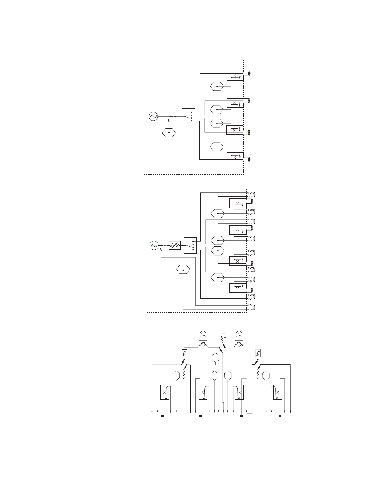
Test Set Block Diagrams
N5230A Option 140 or 240
standard test set and
standard power range
PORT 4
D
N5230A Option 145 or 245
configurable test set,
extended power range
Source
Reference
receiver
Source
R
Reference
receiver
60 dB
R
Switch
Switch
C
B
A
D
C
B
A
PORT 3
PORT 2
PORT 1
Source out
Coupler thru
PORT 4
Coupler arm
Receiver D in
Source out
Coupler thru
PORT 3
Coupler arm
Receiver C in
Receiver B in
Coupler arm
PORT 2
Coupler thru
Source out
Receiver A in
Coupler arm
PORT 1
Coupler thru
Source out
Source out
Receiver R in
N5230A Option 146 or 246
configurable test set,
extended power range,
and internal second source
Source 1
60 dB 60 dB
A B C D
Test port 2Test port 1
R
Source 2
Test port 3
Test port 4
31
Page 32

Agilent Email Updates
t
www.agilent.com/find/emailupdates
Get the latest information on the products
and applications you select.
Agilent Direc
www.agilent.com/find/agilentdirect
Quickly choose and use your test
equipment solutions with confidence.
Agilent
Open
www.agilent.com/find/open
Agilent Open simplifies the process of
connecting and programming test systems
to help engineers design, validate and
manufacture electronic products. Agilent
offers open connectivity for a broad range
of system-ready instruments, open industry
software, PC-standard I/O and global
support, which are combined to more
easily integrate test system development.
Remove all doubt
Our repair and calibration services will get
your equipment back to you, performing
like new, when promised. You will get
full value out of your Agilent equipment
throughout its lifetime. Your equipment
will be serviced by Agilent-trained technicians using the latest factory calibration
procedures, automated repair diagnostics
and genuine parts. You will always have the
utmost confidence in your measurements.
Agilent offers a wide range of additional
expert test and measurement services for
your equipment, including initial start-up
assistance onsite education and training,
as well as design, system integration, and
project management.
For more information on repair and
calibration services, go to
www.agilent.com/find/ removealldoubt
www.agilent.com
For more information on Agilent Technologies’ products, applications or services,
please contact your local Agilent office.
The complete list is available at:
www.agilent.com/find/contactus
Americas
Canada (877) 894-4414
Latin America 305 269 7500
United States (800) 829-4444
Asia Pacific
Australia 1 800 629 485
China 800 810 0189
Hong Kong 800 938 693
India 1 800 112 929
Japan 0120 (421) 345
Korea 080 769 0800
Malaysia 1 800 888 848
Singapore 1 800 375 8100
Taiwan 0800 047 866
Thailand 1 800 226 008
Europe & Middle East
Austria 01 36027 71571
Belgium 32 (0) 2 404 93 40
Denmark 45 70 13 15 15
Finland 358 (0) 10 855 2100
France 0825 010 700*
*0.125 €/minute
Germany 07031 464 6333
Ireland 1890 924 204
Israel 972-3-9288-504/544
Italy 39 02 92 60 8484
Netherlands 31 (0) 20 547 2111
Spain 34 (91) 631 3300
Sweden 0200-88 22 55
Switzerland 0800 80 53 53
United Kingdom 44 (0) 118 9276201
Other European Countries:
www.agilent.com/find/contactus
Revised: October 6, 2008
Intel® and Pentium® are US registered trademarks of
Intel Corporation.
Product specifications and
descriptions in this document
subject to change without notice.
© Agilent Technologies, Inc. 2003-2009
Printed in USA, February 18, 2009
5989-1695EN
 Loading...