

Page 1
Agilent
2-Port and 4-Port
PNA Network Analyzer
N5227A 10 MHz to 67 GHz
Data Sheet and
Technical Specifications
Page 2

Documentation Warranty
THE MATERIAL CONTAINED IN THIS DOCUMENT IS PROVIDED "AS IS," AND IS SUBJECT TO BEING
CHANGED, WITHOUT NOTICE, IN FUTURE EDITIONS. FURTHER, TO THE MAXIMUM EXTENT
PERMITTED BY APPLICABLE LAW, AGILENT DISCLAIMS ALL WARRANTIES, EITHER EXPRESS OR
IMPLIED WITH REGARD TO THIS MANUAL AND ANY INFORMATION CONTAINED HEREIN,
INCLUDING BUT NOT LIMITED TO THE IMPLIED WARRANTIES OF MERCHANTABILITY AND
FITNESS FOR A PARTICULAR PURPOSE. AGILENT SHALL NOT BE LIABLE FOR ERRORS OR FOR
INCIDENTAL OR CONSEQUENTIAL DAMAGES IN CONNECTION WITH THE FURNISHING, USE, OR
PERFORMANCE OF THIS DOCUMENT OR ANY INFORMATION CONTAINED HEREIN. SHOULD
AGILENT AND THE USER HAVE A SEPARATE WRITTEN AGREEMENT WITH WARRANTY TERMS
COVERING THE MATERIAL IN THIS DOCUMENT THAT CONFLICT WITH THESE TERMS, THE
WARRANTY TERMS IN THE SEPARATE AGREEMENT WILL CONTROL.
DFARS/Restricted Rights Notice
If software is for use in the performance of a U.S. Government prime contract or subcontract, Software
is delivered and licensed as “Commercial computer software” as defined in DFAR 252.227-7014 (June
1995), or as a “commercial item” as defined in FAR 2.101(a) or as “Restricted computer software” as
defined in FAR 52.227-19 (June 1987) or any equivalent agency regulation or contract clause. Use,
duplication or disclosure of Software is subject to Agilent Technologies’ standard commercial license
terms, and non-DOD Departments and Agencies of the U.S. Government will receive no greater than
Restricted Rights as defined in FAR 52.227-19(c)(1-2) (June 1987). U.S. Government users will receive
no greater than Limited Rights as defined in FAR 52.227-14 (June 1987) or DFAR 252.227-7015 (b)(2)
(November 1995), as applicable in any technical data.
2
Page 3

Documentation Warranty ..................................................................................................................................... 2
DFARS/Restricted Rights Notice ....................................................................................................................... 2
Definitions ...................................................................................................................................................... 5
Corrected System Performance .......................................................................................................................... 6
System Dynamic Range and Receiver Dynamic Range ........................................................................... 6
Table 1. System Dynamic Range and Receiver Dynamic Range, Option 200, 400 .............................. 6
Table 2. System Dynamic Range at Test Port (dB) .................................................................................. 8
Table 3. Extended Dynamic Range at Direct Receiver Access Input (dB) - Specification ................ 9
N5227A Corrected System Performance, All Options ........................................................................... 10
Table 4a. N5227A with 85058B Calibration Kit ..................................................................................... 10
Table 4b. N5227A with N4694A 2-Port Electronic Calibration Module ............................................. 12
Uncorrected System Performance.................................................................................................................... 14
Table 5a. Error Terms (dB), All Ports, All Options - Specifications ................................................... 14
Table 5b. Error Terms (dB), All Ports, All Options - Typical ............................................................... 15
Test Port Output .................................................................................................................................................. 16
Table 6. Frequency Information, All Options ......................................................................................... 16
Table 7a. Maximum Leveled Power (dBm) - Specification ................................................................... 16
Table 7b. Maximum Leveled Power (dBm) - Typical ............................................................................. 17
Table 8. Power Level Accuracy (dB), All Options .................................................................................. 18
Table 9a. Power Level Linearity (dB), All Options - Specification ...................................................... 18
Table 9b. Power Level Linearity (dB), All Options - Specification ..................................................... 18
Table 10a. Power Sweep Range (dB) - Specification ............................................................................. 19
Table 10b. Power Sweep Range (dB) - Typical ....................................................................................... 20
Table 11. Nominal (Preset) Power (dBm)................................................................................................ 20
Table 12. Power Resolution and Maximum/Minimum Settable Power, All Models and Options .. 21
Table 13. 2nd and 3rd Harmonics at Max Specified Power (dBc) All Options - Typical .................... 21
Table 14. Non-Harmonic Spurs at Nominal Power (dBc), All Options - Typical .............................. 21
Table 15. Phase Noise (dBc/Hz), All Options - Typical ......................................................................... 22
Test Port Input ..................................................................................................................................................... 23
Table 16. Test Port Noise Floor (dBm) @ 10 Hz IFBW, All Options .................................................... 23
Table 17. Direct Receiver Access Input Noise Floor (dBm) ................................................................. 24
Table 18a. 0.1 dB Receiver Compression at Test Port (dBm), Option 201, 219, 401, 419 - Typical25
Table 18b. Receiver Compression at Test Port Power - Specification ................................................ 25
Table 19. N5227A Trace Noise Magnitude (dB rms) .............................................................................. 26
Table 20. N5227A Trace Noise Phase (deg rms) ..................................................................................... 26
Table 21. Reference Level Magnitude, All Models and Options - Specification ................................ 26
Table 22. Stability, All Options - Typical ................................................................................................. 27
Table 23. Damage Input Level, All Options ............................................................................................. 27
Dynamic Accuracy .............................................................................................................................................. 28
3
Page 4

Table 24. N5227A Dynamic Accuracy ...................................................................................................... 28
Table 25. Group Delay - Typical ................................................................................................................ 32
General Information ............................................................................................................................................ 33
Table 26. Miscellaneous Information ....................................................................................................... 33
Table 27. Front Panel Information, All Options ..................................................................................... 33
Table 28. Rear Panel Information, All Options....................................................................................... 34
Table 29. Analyzer Dimensions and Weight............................................................................................ 38
Regulatory and Environmental Information .......................................................................................... 38
Measurement Throughput Summary................................................................................................................ 39
Table 30. Typical Cycle Time (ms) for Measurement Completion, All Models and Options ........... 39
Table 31. Typical Cycle Time (ms) for Full-Span Measurement Completion ................................... 40
Table 32. Cycle Time vs. IF Bandwidth - Typical ................................................................................... 40
Table 33. Cycle Time vs. Number of Points - Typical ............................................................................ 41
Table 34. Data Transfer Time (ms) - Typical .......................................................................................... 42
Specifications: Front-Panel Jumpers ............................................................................................................... 43
Table 35. Measurement Receiver Inputs (dBm) - Typical ..................................................................... 43
Table 36. Port 1 Reference Receiver Inputs and Reference Source Outputs (dBm) - Typical ........ 44
Table 37. Port 2, 3, 4 Reference Receiver Inputs and Reference Source Outputs (dBm) - Typical 45
Table 38. Source Outputs (dBm) - Typical .............................................................................................. 46
Table 39. Coupler Inputs (dB) - Typical .................................................................................................. 47
Table 40 Damage Level, All Options - Typical ........................................................................................ 47
Test Set Block Diagrams.................................................................................................................................... 48
N5227A Option 200 (2-port base model) ................................................................................................ 48
N5227A Option 201 ..................................................................................................................................... 48
N5227A Option 219 ..................................................................................................................................... 49
N5227A Option 400 (4-port base model) ................................................................................................ 49
N5227A Option 401 ..................................................................................................................................... 50
N5227A Option 419 ..................................................................................................................................... 50
Receiver Block Diagram ............................................................................................................................. 51
4
Page 5

This is a complete list of the technical specifications for the N5227A PNA network analyzer with
Notes
This document provides technical specifications for the 85058B and N4694A calibration kits.
Please download our free Uncertainty Calculator from http://www.agilent.com/find/na_calculator to generate the
curves for your calibration kit and PNA setup.
Typical performance information between 67 GHz and 70 GHz is shown in this document where available. The
performance is degraded at particular frequencies in this range due to the modes of the 1.85 mm connectors used
in the analyzer, test port cables and adapters.
For all tables in this data sheet, the specified performance at the exact frequency of a break is the degraded value
of the two specifications at that frequency.
the following options. See block diagrams for all models and options beginning on page 47.
2-Port Models
Option 200 - 2-port base model with standard test set.
Option 201 - To base model, adds front-panel jumpers and R1 receiver switch.
Option 219 - To base model, adds front-panel jumpers, R1 receiver switch, source and receiver
attenuators (extended power range), and bias-tees.
4-Port Models
Option 400 - 4-port base model with standard test set.
Option 401 - To base model, adds front-panel jumpers and R1 receiver switch.
Option 419 - To base model, adds front-panel jumpers, R1 receiver switch, source and receiver
attenuators (extended power range), and bias-tees.
Definitions
All specifications and characteristics apply over a 25 °C ±5 °C range (unless otherwise stated) and 90
minutes after the instrument has been turned on.
Specification (spec.): Warranted performance. Specifications include guardbands to account for the
expected statistical performance distribution, measurement uncertainties, and changes in performance
due to environmental conditions.
Characteristic (char.): A performance parameter that the product is expected to meet before it leaves
the factory, but that is not verified in the field and is not covered by the product warranty. A
characteristic includes the same guardbands as a specification.
Typical (typ.): Expected performance of an average unit which does not include guardbands. It is not
covered by the product warranty.
Nominal (nom.): A general, descriptive term that does not imply a level of performance. It is not
covered by the product warranty.
Calibration: The process of measuring known standards to characterize a network analyzer's
systematic (repeatable) errors.
Corrected (residual): Indicates performance after error correction (calibration). It is determined by
the quality of calibration standards and how well "known" they are, plus system repeatability, stability,
and noise.
Uncorrected (raw): Indicates instrument performance without error correction. The uncorrected
performance affects the stability of a calibration.
Standard: When referring to the analyzer, this includes no options unless noted otherwise.
5
Page 6
Corrected System Performance
Description
Specification
Typical
System
Max
Test Port
Receiver
0.1 dB
Test Port
The specifications in this section apply for measurements made with the N5227A PNA network
analyzer with the following conditions:
10 Hz IF bandwidth
No averaging applied to data
Isolation calibration with an averaging factor of 8
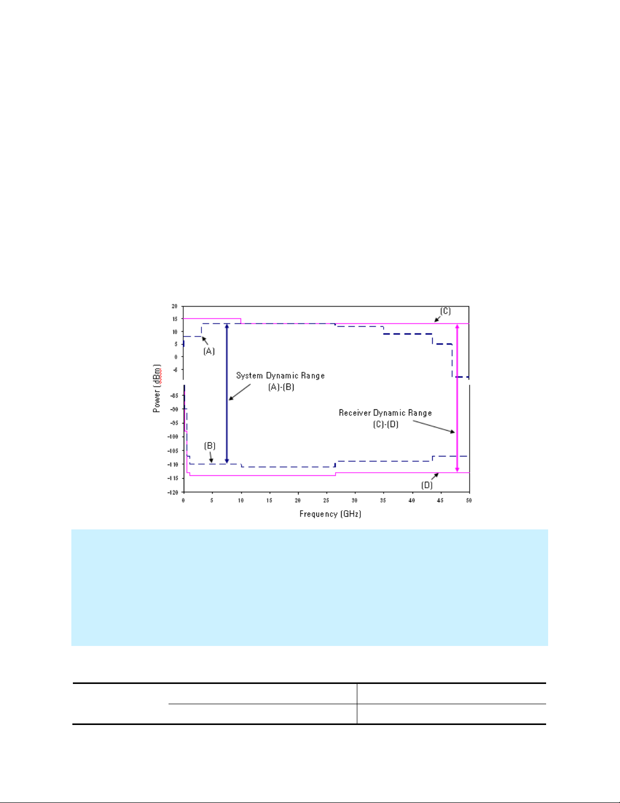
System Dynamic Range and Receiver Dynamic Range
System Dynamic Range is defined as the specified source maximum output power (spec) minus
the noise floor (spec).
Extended Dynamic Range at Direct Access Input is defined as the specified source maximum
output power (spec) minus the direct receiver access input noise floor (spec).
Receiver Dynamic Range is defined as the test port compression at 0.1 dB (typical) minus the
noise floor (typical).
NOTE:
The effective dynamic range must take measurement uncertainties and interfering signals into account. This set-up
should only be used when the receiver input will never exceed its maximum receiver input. When the analyzer is in
segment sweep mode, it can have predefined frequency segments which will output a higher power level when the
extended dynamic range is required (i.e. devices with high insertion loss), and reduced power when the maximum
receiver input level will occur (i.e. devices with low insertion loss). The extended range is only available in one-path
transmission measurements.
It may typically be degraded at particular frequencies below 500 MHz due to spurious receiver residuals.
Table 1. System Dynamic Range and Receiver Dynamic Range, Option 200, 400
6
Page 7

Dynamic
Range (dB)
(A)-(B)
Leveled
Output
Power
(dBm)
(A)
Noise Floor
(dBm)
(B)
Dynamic
Range (dB)
(C)-(D)
Compression
at Test Port
(dBm)
(C)
Noise Floor
(dBm)
(D)
10 MHz to 50 MHz
82
12
-70
91
15
-76
50 MHz to 100 MHz
105
13
-92
112
15
-97
100 MHz to 500 MHz
114
13
-101
118
12
-106
500 MHz to 1 GHz
123
13
-110
127
12
-115
1 GHz to 10 GHz
127
13
-114
131
12
-119
10 GHz to 13.5 GHz
126
12
-114
132
12
-120
13.5 GHz to 16 GHz
128
12
-116
133
12
-121
16 GHz to 24 GHz
127
11
-116
133
12
-121
24 GHz to 26.5 GHz
128
11
-117
133
12
-121
26.5 GHz to 30 GHz
116
10
-106
124
12
-112
30 GHz to 32 GHz
115 9 -106
123
11
-112
32 GHz to 35 GHz
116
10
-106
123
11
-112
35 GHz to 40 GHz
109 5 -104
121
11
-110
40 GHz to 50 GHz
112
11
-101
119
11
-108
50 GHz to 60 GHz
112
11
-101
118
11
-107
60 GHz to 67 GHz
112
11
-101
119
11
-108
67 GHz to 70 GHz
--
--
--
117
11
-106
7
Page 8

Table 2. System Dynamic Range at Test Port (dB)
Description
Specification
Typical
Option 200,
400
Option 201,
401
Option 219,
419
Option 200,
400
Option 201,
401
Option 219,
419
10 MHz to 50 MHz
82
82
81
96
95
95
50 MHz to 100 MHz
105
105
105
117
117
116
100 MHz to 500 MHz
114
114
114
126
126
125
500 MHz to 1 GHz
123
123
123
136
135
134
1 GHz to 2 GHz
127
127
127
139
139
137
2 GHz to 3.2 GHz
127
127
127
137
136
136
3.2 GHz to 10 GHz
127
127
126
138
138
137
10 GHz to 13.5 GHz
126
125
123
138
137
136
13.5 GHz to 16 GHz
128
128
126
140
139
138
16 GHz to 19 GHz
127
126
124
138
138
135
19 GHz to 20 GHz
127
127
124
138
138
134
20 GHz to 24 GHz
127
127
124
137
137
134
24 GHz to 26.5 GHz
128
128
124
136
136
133
26.5 GHz to 30 GHz
116
116
113
127
127
124
30 GHz to 32 GHz
115
113
111
126
125
123
32 GHz to 35 GHz
116
115
112
127
126
124
35 GHz to 40 GHz
109
109
105
123
122
119
40 GHz to 43.5 GHz
112
111
107
120
120
119
43.5 GHz to 50 GHz
112
111
107
121
120
118
50 GHz to 60 GHz
112
111
106
120
119
117
60 GHz to 64 GHz
112
111
106
121
120
117
64 GHz to 67 GHz
112
111
105
122
121
116
67 GHz to 70 GHz
--
--
--
--
--
110
8
Page 9

Table 3. Extended Dynamic Range at Direct Receiver Access Input (dB) - Specification
Description
Option 201, 401
Option 219, 419
10 MHz to 50 MHz
--
--
50 MHz to 100 MHz
117
117
100 MHz to 500 MHz
126
126
250 MHz to 500 MHz
126
126
500 MHz to 1 GHz
135
135
1 GHz to 2 GHz
139
139
2 GHz to 3.2 GHz
138
138
3.2 GHz to 10 GHz
138
137
10 GHz to 13.5 GHz
136
134
13.5 GHz to 16 GHz
139
137
16 GHz to 19 GHz
137
135
19 GHz to 24 GHz
138
135
24 GHz to 26.5 GHz
139
135
26.5 GHz to 30 GHz
127
124
30 GHz to 32 GHz
123
121
32 GHz to 35 GHz
125
122
35 GHz to 40 GHz
119
115
40 GHz to 45 GHz
121
117
45 GHz to 50 GHz
120
116
50 GHz to 64 GHz
119
114
64 GHz to 67 GHz
119
113
9
Page 10

N5227A Corrected System Performance, All Options
Description
Specification (dB)
10 MHz
to
50 MHz
50 MHz
to
2 GHz
2 GHz
to
10 GHz
10 GHz
to
20 GHz
20 GHz
to
35 GHz
35 GHz
to
50 GHz
50 GHz
to
60 GHz
60 GHz
to
67 GHz
Directivity
35
35
38
38
37
37
34
34
Source Match
34
34
40
40
41
42
40
40
Load Match
34
35
37
37
36
36
33
33
Reflection Tracking
Mag
0.019
0.019
0.033
0.033
0.033
0.020
0.030
0.030
Phase (°)
0.125
0.125
0.218
0.218
0.218
0.132
0.198
0.198
Transmission Tracking
Mag
0.159
0.128
0.099
0.094
0.100
0.093
0.121
0.137
Phase (°)
1.047
0.845
0.655
0.619
0.663
0.616
0.801
0.903
Note: For any Sii reflection measurement:
Sjj = 0.
For any Sij transmission measurement:
Sji = Sij when Sij 1
Sji = 1/Sij when Sij 1
Skk = 0 for all k
Applies to the N5227A Option 200, 201, 219, 400, 401, or 419 analyzers, N4697F flexible test port cable set, and a full 2 port calibration. Also applies to the following condition:
Environmental temperature 23° ±3 °C, with < 1 °C deviation from calibration temperature
Table 4a. N5227A with 85058B Calibration Kit
10
Page 11
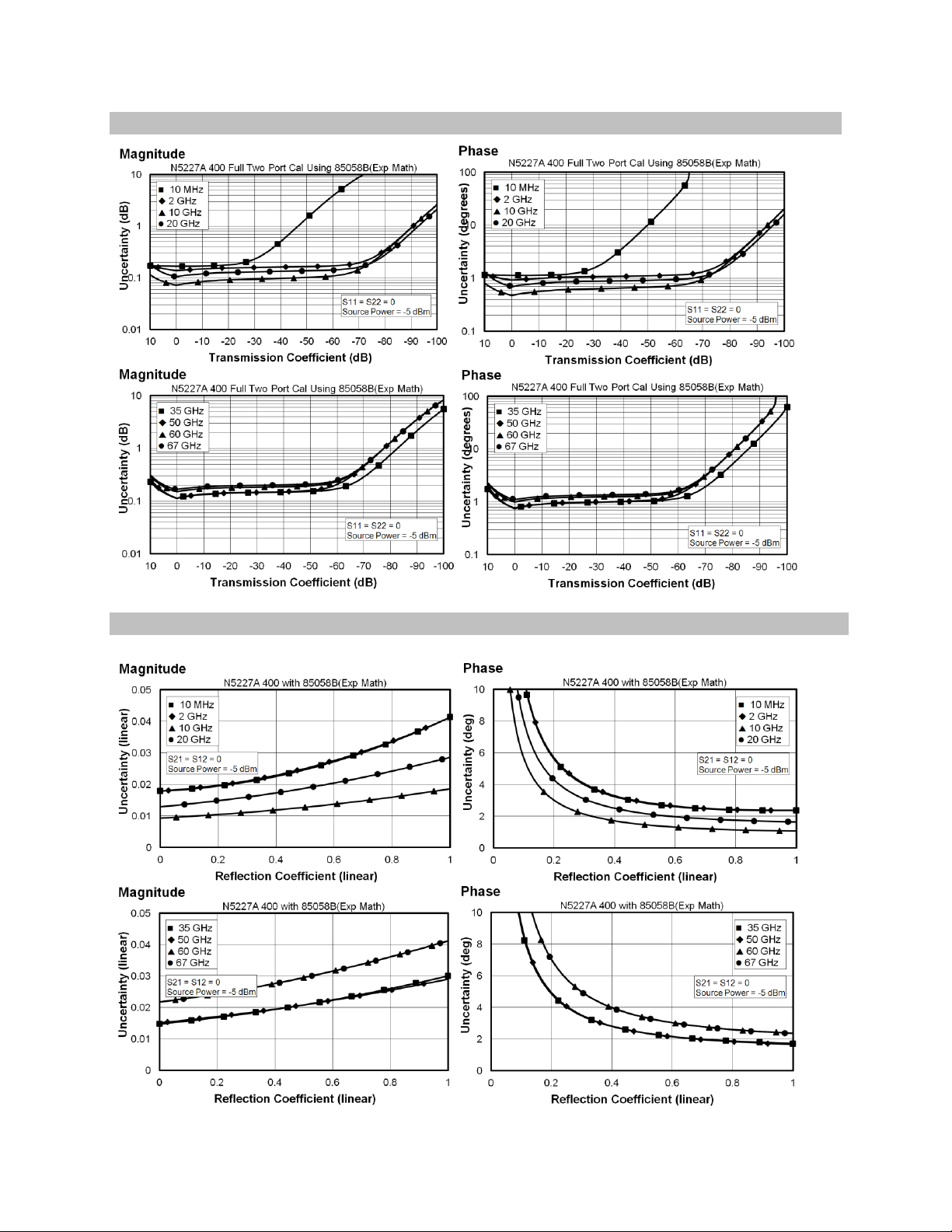
Transmission Uncertainty, All Options
Reflection Uncertainty, All Options
11
Page 12

Table 4b. N5227A with N4694A 2-Port Electronic Calibration Module
Description
Specification (dB)
10 MHz
to
50 MHz
50 MHz
to
2 GHz
2 GHz
to 20
GHz
20 GHz
to
30 GHz
30 GHz
to 40
GHz
40 GHz
to
50 GHz
50 GHz
to
60 GHz
60 GHz
to
67 GHz
Directivity
33
41
47
46
44
42
41
38
Source Match
25
38
39
35
34
33
30
27
Load Match
25
37
38
34
33
32
29
26
Reflection Tracking
Mag
±0.050
±0.040
±0.040
±0.050
±0.060
±0.070
±0.080
±0.090
Phase (°)
±0.330
±0.264
±0.264
±0.330
±0.396
±0.462
±0.528
±0.594
Transmission Tracking
Mag
±0.146
±0.059
±0.057
±0.072
±0.087
±0.104
±0.114
±0.144
Phase (°)
±0.966
±0.392
±0.378
±0.473
±0.576
±0.688
±0.754
±0.951
12
Page 13
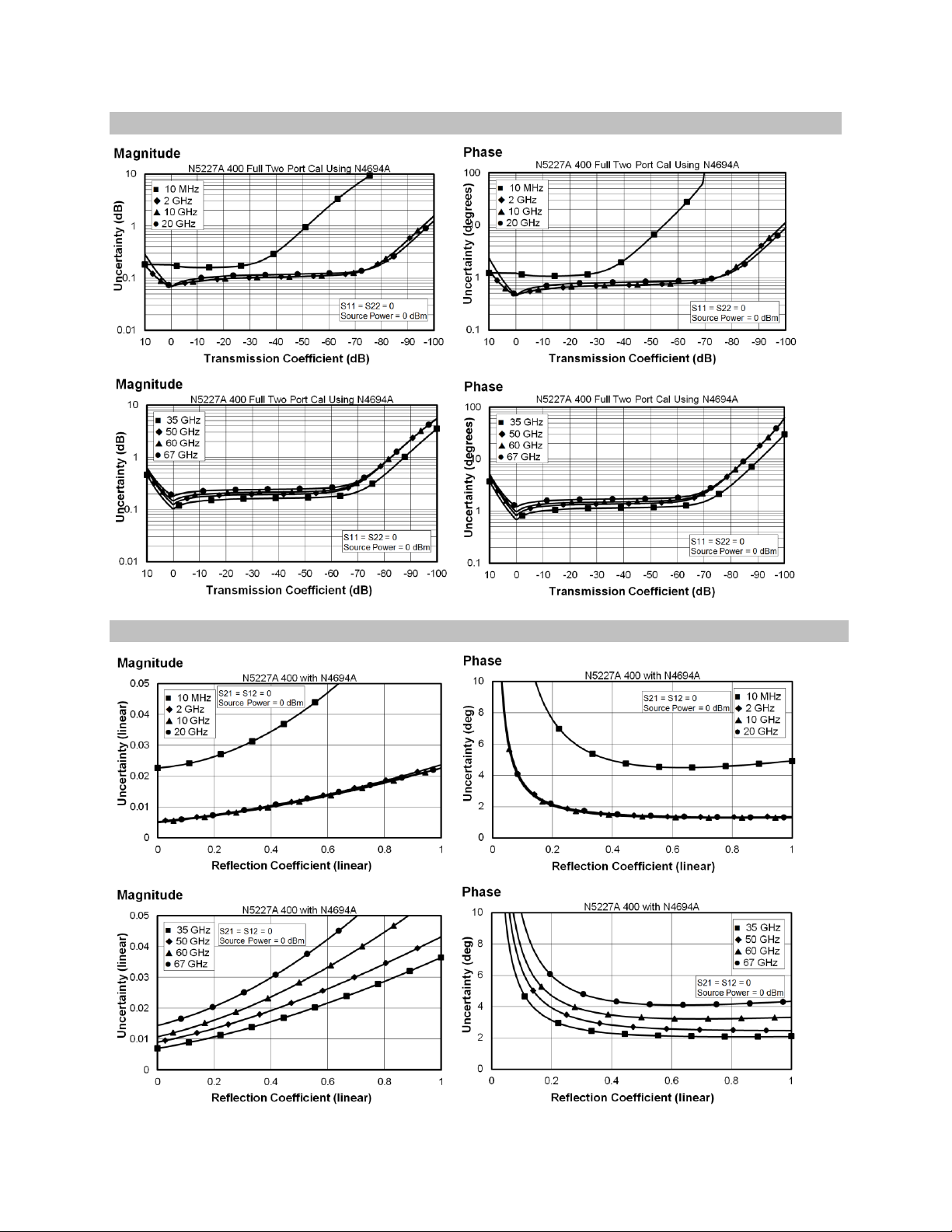
Transmission Uncertainty, All Options
Reflection Uncertainty, All Options
13
Page 14

Uncorrected System Performance
Directivity
Source
Match
Load Match
Transmission
Tracking
Reflection
Tracking
Crosstalk
10 MHz to 50 MHz
17 7 6
--
--
--
50 MHz to 500 MHz
24
15
11
--
--
--
500 MHz to 2 GHz
24
10 7 --
--
--
2 GHz to 3.2 GHz
20
10 7
3.2 GHz to 10 GHz
20 7 7
--
--
--
10 GHz to 16 GHz
16 7 6
--
--
--
16 GHz to 20 GHz
16 7 7
--
--
--
20 GHz to 26.5 GHz
14 7 7
26.5 GHz to 50 GHz
13 7 6
--
--
--
50 GHz to 60 GHz
13 7 7
--
--
--
60 GHz to 67 GHz
10 6 6
--
--
--
67 GHz to 70 GHz
--
--
--
--
--
--
Specifications apply to following conditions:
Over environmental temperature of 25 °C ±5 °C, with less than 1°C variation from the calibration temperature.
Cable loss not included in Transmission Tracking.
Crosstalk measurement conditions: normalized to a thru, measured with shorts on all ports, 10 Hz IF
bandwidth, averaging factor of 8, alternate mode, source power set to the specified maximum power.
Table 5a. Error Terms (dB), All Ports, All Options - Specifications
14
Page 15

Table 5b. Error Terms (dB), All Ports, All Options - Typical
Directivity
Source
Match
Load Match
Transmission
Tracking
Reflection
Tracking
Crosstalk
10 MHz to 50 MHz
20 9 8
+/- 1.0
+/- 1.0
-90
50 MHz to 200 MHz
28
19
17
+/- 1.0
+/- 1.0
-109
200 MHz to 500 MHz
28
19
17
+/- 1.0
+/- 1.0
-123
500 MHz to 2 GHz
31
14
12
+/- 1.0
+/- 1.0
-124
2 GHz to 3.2 GHz
28
14
12
+/- 1.0
+/- 1.0
-124
3.2 GHz to 10 GHz
25
11
10
+/- 1.0
+/- 1.0
-124
10 GHz to 13.5 GHz
23
10
10
+/- 1.0
+/- 1.0
-124
13.5 GHz to 16 GHz
23
11
11
+/- 1.0
+/- 1.0
-124
16 GHz to 20 GHz
20
11
11
+/- 1.0
+/- 1.0
-124
20 GHz to 26.5 GHz
18
11
11
+/- 1.0
+/- 1.0
-124
26.5 GHz to 43.5 GHz
16
11
11
+/- 1.0
+/- 1.0
-115
43.5 GHz to 50 GHz
19
11
11
+/- 1.0
+/- 1.0
-113
50 GHz to 60 GHz
16
11
12
+/- 1.0
+/- 1.0
-113
60 GHz to 67 GHz
16 9 10
+/- 1.0
+/- 1.0
-113
67 GHz to 70 GHz
15
10
10
+/- 1.0
+/- 1.5
-110
15
Page 16

Test Port Output
Description
Specification
Typical
N5227A Frequency Range
10 MHz to 67 GHz
67 GHz to 70 GHz
Frequency Resolution
1 Hz
--
Frequency Accuracy
+/- 1 ppm
--
Frequency Stability
--
+/-0.05 ppm, -10° to 70° C1
+/-0.1 ppm/yr maximum2
Description
Option 200, 400
Option 201, 401
Option 219, 419
Port 1,
Port 3
Port 2,
Port 4
Port 1,
Port 3
Port 2,
Port 4
Port 1,
Port 3
Port 2,
Port 4
10 MHz to 50 MHz
12
12
12
12
11
11
50 MHz to 2 GHz
13
13
13
13
13
13
2 GHz to 3.2 GHz
10
13
10
13 9 13
3.2 GHz to 10 GHz
13
13
13
13
11
12
10 GHz to 13.5 GHz
12
12
11
11 9 9
13.5 GHz to 16 GHz
12
12
12
12
10
10
16 GHz to 19 GHz
11
11
10
10 8 8
19 GHz to 24 GHz
11
11
11
11 8 8
24 GHz to 26.5 GHz
11
11
11
11 7 7
26.5 GHz to 30 GHz
10
10
10
10 7 7
30 GHz to 32 GHz
9 9 7 7 5
5
32 GHz to 35 GHz
10
10 9 9 6 6
35 GHz to 40 GHz
5 5 5 5 1
1
40 GHz to 50 GHz
11
11
10
10 6 6
50 GHz to 64 GHz
11
11
10
10 5 5
64 GHz to 67 GHz
11
11
10
10 4 4
Table 6. Frequency Information, All Options
1
Assumes no variation in time.
2
Assumes no variation in temperature.
Table 7a. Maximum Leveled Power (dBm) - Specification
16
Page 17

Table 7b. Maximum Leveled Power (dBm) - Typical
Description
Option 200, 400
Option 201, 401
Option 219, 419
Port 1,
Port 3
Port 2,
Port 4
Port 1,
Port 3
Port 2,
Port 4
Port 1,
Port 3
Port 2,
Port 4
10 MHz to 50 MHz
20
17
19
17
19
17
50 MHz to 500 MHz
20
18
20
18
19
17
500 MHz to 1 GHz
20
21
20
20
19
18
1 GHz to 2 GHz
18
20
18
20
17
18
2 GHz to 3.2 GHz
17
18
17
17
15
17
3.2 GHz to 10 GHz
19
19
19
18
18
18
10 GHz to 13.5 GHz
18
16
17
15
16
14
13.5 GHz to 16 GHz
19
18
18
17
17
16
16 GHz to 19 GHz
17
17
17
16
14
14
19 GHz to 20 GHz
17
17
17
16
13
13
20 GHz to 24 GHz
16
16
16
15
12
13
24 GHz to 30 GHz
15
15
15
14
12
12
30 GHz to 32 GHz
14
14
13
13
11
11
32 GHz to 35 GHz
15
15
14
14
12
12
35 GHz to 40 GHz
13
13
12
11 9 9
40 GHz to 43.5 GHz
12
12
11
12
11
10
43.5 GHz to 50 GHz
12
13
11
12
10
10
50 GHz to 60 GHz
12
13
12
12
10
9
60 GHz to 64 GHz
12
13
12
12 9 9
64 GHz to 67 GHz
13
14
13
13 8 8
67 GHz to 70 GHz
13
14
12
12 4 4
17
Page 18

Table 8. Power Level Accuracy (dB), All Options
Description
Specification
Typical
10 MHz to 50 MHz
+/- 1.2
+/- 0.4
50 MHz to 1 GHz
+/- 1.0
+/- 0.4
1 GHz to 3.2 GHz
+/- 1.0
+/- 0.2
3.2 GHz to 20 GHz
+/- 2.0
+/- 0.4
20 GHz to 26.5 GHz
+/- 2.2
+/- 0.4
26.5 GHz to 40 GHz
+/- 3.0
+/- 0.5
40 GHz to 43.5 GHz
+/- 3.0
+/- 0.3
43.5 GHz to 50 GHz
+/- 3.0
+/- 0.5
50 GHz to 60 GHz
+/- 3.5
+/- 0.6
60 GHz to 67 GHz
+/- 4.0
+/- 0.7
67 GHz to 70 GHz
--
+/- 1.0
Description
Specification
Port 1 or 31
-25dBm ≤ P<-20dBm
Port 1 or 31
-20dBm ≤ P<-15dBm
Port 1 or 31
P ≥-15dBm
10 MHz to 50 MHz
+/-2.5
+/-1.5
+/-1.5
50 MHz to 67 GHz
+/-1.5
+/-1.5
+/-1.5
Description
Specification
Port 2 or 41
-25dBm ≤ P<-20dBm
Port 2 or 41
-20dBm ≤ P<-15dBm
Port 2 or 41
P ≥-15dBm
10 MHz to 50 MHz
+/-3.5
+/-1.5
+/-1.5
50 MHz to 500 MHz
+/-2.5
+/-1.5
+/-1.5
500 MHz to 3.2 GHz
+/-2.5
+/-1.5
+/-1.5
3.2 GHz to 67 GHz
+/-1.5
+/-1.5
+/-1.5
Table 9a. Power Level Linearity (dB), All Options - Specification
1
Either port can be used as the source port.
Table 9b. Power Level Linearity (dB), All Options - Specification
1
Either port can be used as the source port.
18
Page 19

Table 10a. Power Sweep Range (dB) - Specification
Description
Option 200, 400
Option 201, 401
Option 219, 419
Port 1,
Port 3
Port 2,
Port 4
Port 1,
Port 3
Port 2,
Port 4
Port 1,
Port 3
Port 2,
Port 4
10 MHz to 50 MHz
37
37
37
37
36
36
50 MHz to 2 GHz
38
38
38
38
38
38
2 GHz to 3.2 GHz
35
38
35
38
34
38
3.2 GHz to 10 GHz
38
38
38
38
36
37
10 GHz to 13.5 GHz
37
37
36
36
34
34
13.5 GHz to 16 GHz
37
37
37
37
35
35
16 GHz to 19 GHz
36
36
35
35
33
33
19 GHz to 24 GHz
36
36
36
36
33
33
24 GHz to 26.5 GHz
36
36
36
36
32
32
26.5 GHz to 30 GHz
35
35
35
35
32
32
30 GHz to 32 GHz
34
34
32
32
30
30
32 GHz to 35 GHz
35
35
34
34
31
31
35 GHz to 40 GHz
30
30
30
30
26
26
40 GHz to 50 GHz
36
36
35
35
31
31
50 GHz to 64 GHz
36
36
35
35
30
30
64 GHz to 67 GHz
36
36
35
35
29
29
19
Page 20

Table 10b. Power Sweep Range (dB) - Typical
Description
Option 200, 400
Option 201, 401
Option 219, 419
Port 1,
Port 3
Port 2,
Port 4
Port 1,
Port 3
Port 2,
Port 4
Port 1,
Port 3
Port 2,
Port 4
10 MHz to 50 MHz
47
44
46
44
46
44
50 MHz to 500 MHz
47
45
47
45
46
44
500 MHz to 1 GHz
47
48
47
47
46
45
1 GHz to 2 GHz
45
47
45
47
44
45
2 GHz to 3.2 GHz
44
45
44
44
42
44
3.2 GHz to 10 GHz
46
46
46
45
45
45
10 GHz to 13.5 GHz
45
43
44
42
43
41
13.5 GHz to 16 GHz
46
45
45
44
44
43
16 GHz to 19 GHz
44
44
44
43
41
41
19 GHz to 20 GHz
44
44
44
43
40
40
20 GHz to 24 GHz
43
43
43
42
39
40
24 GHz to 30 GHz
42
42
42
41
39
39
30 GHz to 32 GHz
41
41
40
40
38
38
32 GHz to 35 GHz
42
42
41
41
39
39
35 GHz to 40 GHz
40
40
39
38
36
36
40 GHz to 43.5 GHz
39
39
38
39
38
37
43.5 GHz to 50 GHz
39
40
38
39
37
37
50 GHz to 60 GHz
39
40
39
39
37
36
60 GHz to 64 GHz
39
40
39
39
36
36
64 GHz to 67 GHz
40
41
40
40
35
35
67 GHz to 70 GHz
40
41
39
39
31
31
Description
Option 200, 201, 400, 401
Option 219, 419
Preset Power 0 -5
Table 11. Nominal (Preset) Power (dBm)
20
Page 21

Table 12. Power Resolution and Maximum/Minimum Settable Power, All Models and Options
Description
Specification (dB)
Typical (dBm)
Power Resolution
0.01
--
Maximum Settable Power
--
30
Minimum Settable Power
Option 200, 201, 400, 401
Option 219, 419
--
--
-30
-80
Description
N5227A
20 MHz to 4 GHz
-17
4 GHz to 24 GHz
-20
24 GHz to 27 GHz
-21
27 GHz to 40.5 GHz
-32
40.5 GHz to 67 GHz
-60
67 GHz to 70 GHz
-60
Description
Based on 8kHz offset Frac-N
Based on 100kHz offset Frac-N
10 MHz to 500 MHz
-50
-50
500 MHz to 2 GHz
-60
-42
2 GHz to 4 GHz
-57
-45
4 GHz to 8 GHz
-51
-39
8 GHz to 16 GHz
-45
-33
16 GHz to 32 GHz
-39
-27
32 GHz to 64 GHz
-33
-21
64 GHz to 70 GHz
-27
-15
Table 13. 2nd and 3rd Harmonics at Max Specified Power (dBc) All Options - Typical
Listed frequency is harmonic frequency; test at max specified power
Table 14. Non-Harmonic Spurs at Nominal Power (dBc), All Options - Typical
Offset frequency = 30 kHz to 5 MHz
21
Page 22

Table 15. Phase Noise (dBc/Hz), All Options - Typical
Description
1 kHz Offset
10 kHz Offset
100 kHz Offset
1 MHz Offset
10 MHz to 50 MHz
-100
-95
-95
-120
50 MHz to 1 GHz
-107
-117
-112
-127
1 GHz to 2 GHz
-101
-111
-106
-121
2 GHz to 4 GHz
-95
-105
-100
-115
4 GHz to 8 GHz
-89
-99
-94
-109
8 GHz to 16 GHz
-83
-93
-88
-103
16 GHz to 32 GHz
-77
-87
-82
-97
32 GHz to 64 GHz
-71
-81
-76
-91
64 GHz to 70 GHz
-65
-75
-70
-85
22
Page 23

Test Port Input
Description
Specification
Typical
10 MHz to 50 MHz
-70
-76
50 MHz to 100 MHz
-92
-97
100 MHz to 500 MHz
-101
-106
500 MHz to 1 GHz
-110
-115
1 GHz to 10 GHz
-114
-119
10 GHz to 13.5 GHz
-114
-120
13.5 GHz to 24 GHz
-116
-121
24 GHz to 26.5 GHz
-117
-121
26.5 GHz to 35 GHz
-106
-112
35 GHz to 40 GHz
-104
-110
40 GHz to 50 GHz
-101
-108
50 GHz to 60 GHz
-101
-107
60 GHz to 67 GHz
-101
-108
67 GHz to 70 GHz
--
-106
Table 16. Test Port Noise Floor (dBm) @ 10 Hz IFBW, All Options
Total average (rms) noise power calculated as the mean value of a linear magnitude trace expressed in dBm.
May typically be degraded at particular frequencies below 500 MHz due to spurious receiver residuals.
23
Page 24

Table 17. Direct Receiver Access Input Noise Floor (dBm)
Description
Specification
Typical
Options 201, 219, 401, 419
Options 201, 219, 401, 419
10 MHz to 50 MHz
--
-116
50 MHz to 100 MHz
-104
-124
100 MHz to 500 MHz
-113
-133
500 MHz to 1 GHz
-122
-142
1 GHz to 2 GHz
-126
-133
2 GHz to 10 GHz
-125
-133
10 GHz to 13.5 GHz
-125
-134
13.5 GHz to 24 GHz
-127
-135
24 GHz to 26.5 GHz
-128
-135
26.5 GHz to 30 GHz
-117
-126
30 GHz to 35 GHz
-116
-125
35 GHz to 40 GHz
-114
-123
40 GHz to 45 GHz
-111
-120
45 GHz to 50 GHz
-110
-120
50 GHz to 67 GHz
-109
-118
67 GHz to 70 GHz
--
-116
Total average (rms) noise power calculated as the mean value of a linear magnitude trace expressed in dBm.
May typically be degraded at particular frequencies below 500 MHz due to spurious receiver residuals.
24
Page 25

Table 18a. 0.1 dB Receiver Compression at Test Port (dBm), Option 201, 219, 401, 419 - Typical
Description
N5227A
10 MHz to 100 MHz
15
100 MHz to 30 GHz
12
30 GHz to 67 GHz
11
Description
Test Port Power (dBm)
Receiver Compression
Option 200,
400
Option 201,
401
Option 219,
419
Magnitude (dB)
Phase (degrees)
10 MHz to 500 MHz1
--
--
--
--
--
500 MHz to 2 GHz
10
13
13
0.15
1.2
2 GHz to 3.2 GHz
7
12
11
0.15
1.2
3.2 GHz to 10 GHz
10
13
12
0.15
1.2
10 GHz to 13.5 GHz
8
11 9 0.15
1.2
13.5 GHz to 16 GHz
8
12
10
0.15
1.2
16 GHz to 20 GHz
6
11 8 0.15
1.2
20 GHz to 24 GHz
6
11 8 0.15
1.2
24 GHz to 30 GHz
6
10 8 0.15
1.2
30 GHz to 35 GHz
5 9 8
0.15
1.2
35 GHz to 40 GHz
0 8 8
0.15
1.2
40 GHz to 67 GHz
4
10 8 0.15
1.2
Table 18b. Receiver Compression at Test Port Power - Specification
1
Test port receiver compression at specified input levels below 500 MHz due to coupler roll off in this frequency range.
25
Page 26

Table 19. N5227A Trace Noise Magnitude (dB rms)
Description
Specification
Typical
1 kHz IFBW
1 kHz IFBW
100 kHz IFBW
600 kHz IFBW
10 MHz to 50 MHz
0.05
0.0177
0.173
0.416
50 MHz to 100 MHz
0.004
0.0012
0.012
0.029
100 MHz to 500 MHz
0.002
0.0006
0.006
0.014
500 MHz to 1 GHz
0.002
0.0004
0.003
0.006
1 GHz to 26.5 GHz
0.002
0.0005
0.002
0.005
26.5 GHz to 50 GHz
0.003
0.0006
0.005
0.012
50 GHz to 67 GHz
0.003
0.0007
0.006
0.013
67 GHz to 70 GHz
--
0.0010
0.007
0.016
Description
Specification
Typical
1 kHz IFBW
1 kHz IFBW
100 kHz IFBW
600 kHz IFBW
10 MHz to 50 MHz
0.400
0.1228
1.205
2.928
50 MHz to 100 MHz
0.020
0.0083
0.080
0.196
100 MHz to 500 MHz
0.020
0.0040
0.037
0.097
500 MHz to 1 GHz
0.020
0.0017
0.015
0.037
1 GHz to 26.5 GHz
0.020
0.0075
0.015
0.031
26.5 GHz to 43.5 GHz
0.030
0.0125
0.040
0.091
43.5 GHz to 50 GHz
0.035
0.0149
0.040
0.092
50 GHz to 67 GHz
0.045
0.0200
0.048
0.110
67 GHz to 70 GHz
--
0.0213
0.050
0.119
Description
Magnitude (dB)
Phase (degrees)
Range
+/- 500
+/- 500
Resolution
0.001
0.01
Ratioed measurement, nominal power at test port.
Table 20. N5227A Trace Noise Phase (deg rms)
Ratioed measurement, nominal power at test port.
Table 21. Reference Level Magnitude, All Models and Options - Specification
26
Page 27

Table 22. Stability, All Options - Typical
Description
Magnitude (dB/°C)
Phase (°/°C)
10 MHz to 50 MHz
0.03
0.400
50 MHz to 3.2 GHz
0.01
0.100
3.2 GHz to 20 GHz
0.01
0.200
20 GHz to 32 GHz
0.01
0.300
32 GHz to 35 GHz
0.02
0.400
35 GHz to 50 GHz
0.02
0.400
50 GHz to 67 GHz
0.03
0.600
67 GHz to 70 GHz
0.06
1.200
Description
RF (dBm)
DC (V)
N5227A
27
40
Table 23. Damage Input Level, All Options
27
Page 28
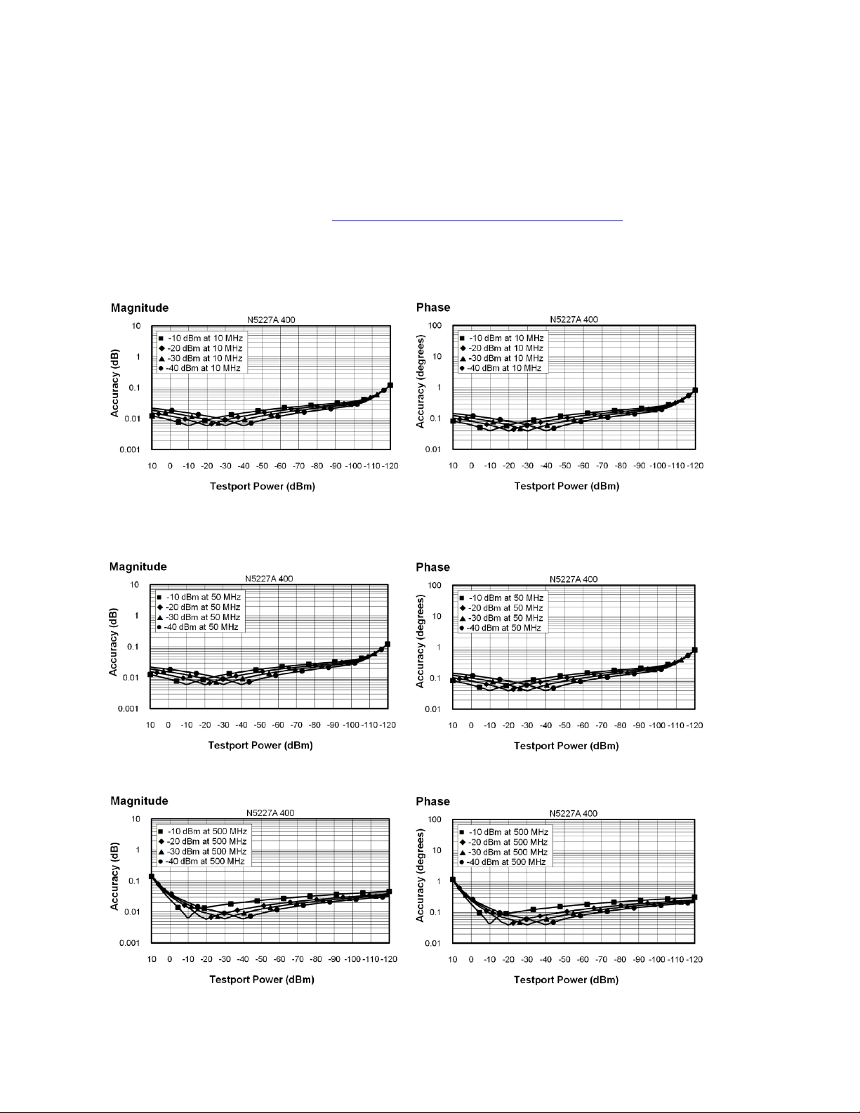
Dynamic Accuracy
Dynamic accuracy is verified with the following measurements:
Compression over frequency
IF linearity at a single frequency of 1.998765GHz using a reference level of -20 dBm for an input power range of 0 to -60
dBm. For values below -60 dBm, refer to “VNA Receiver Dynamic Accuracy Specifications and Uncertainties
Table 24. N5227A Dynamic Accuracy
N5227A Dynamic Accuracy, 10 MHz - Specification
N5227A Dynamic Accuracy, 50 MHz - Specification
N5227A Dynamic Accuracy, 500 MHz - Specification
28
Page 29

N5227A Dynamic Accuracy, 1 GHz - Specification
N5227A Dynamic Accuracy, 2 GHz - Specification
N5227A Dynamic Accuracy, 20 GHz - Specification
29
Page 30

N5227A Dynamic Accuracy, 26.5 GHz - Specification
N5227A Dynamic Accuracy, 35 GHz - Specification
N5227A Dynamic Accuracy, 40 GHz - Specification
30
Page 31
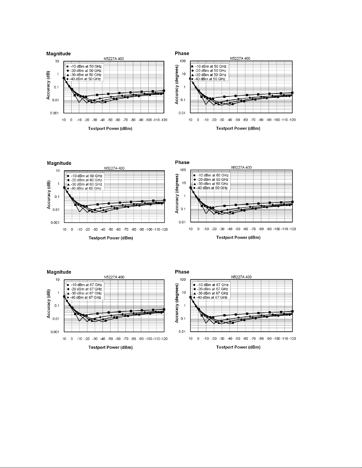
N5227A Dynamic Accuracy, 50 GHz - Specification
N5227A Dynamic Accuracy, 60 GHz - Specification
N5227A Dynamic Accuracy, 67 GHz - Specification
31
Page 32

Table 25. Group Delay - Typical
Description
Typical Performance
Aperture (selectable)
(frequency span)/(number of points -1)
Maximum Aperture
20% of frequency span
Range
0.5 x (1/minimum aperture)
Maximum Delay
Limited to measuring no more than 180° of phase change within the
minimum aperture.)
Group delay is computed by measuring the phase change within a specified frequency step (determined by the
frequency span and the number of points per sweep). In general, the following formula can be used to determine the
accuracy, in seconds, of specific group delay measurement:
±Phase Accuracy (deg)/[360 × Aperture (Hz)]
Depending on the aperture and device length, the phase accuracy used is either incremental phase accuracy or worstcase phase accuracy
The following graph shows characteristic group delay accuracy with full 2-port calibration and a 10 Hz IF bandwidth.
Insertion loss is assumed to be < 2 dB and electrical length to be ten meters.
For any Sij Group Delay measurement, Sii = 0, Sij = 1, Sji = 0, Skl = 0 for all kl ij
32
Page 33

General Information
Description
Supplemental Information
System IF Bandwidth Range
1 Hz to 15 MHz, nominal
CPU
Intel 2.0 GHz Core i7. Note: Some instruments may have a different CPU.
For the latest information on CPUs and associated hard drives, visit:
http://na.tm.agilent.com/pna/hdnumbers.html
LXI
Class C
Description
Typical Performance
RF Connectors
Type
1.85 mm (male), 50 ohm, (nominal)
Center Pin
Recession
0.002 in. (characteristic)
USB 2.0 Ports - Master (4 ports)
Standard
Compatible with USB 2.0
Connector
USB Type-A female
Display
Size
26.3 cm (10.4 in) diagonal color active matrix LCD; 1024 (horizontal) X 768 (vertical) resolution
Refresh Rate
Vertical 60 Hz; Horizontal 46.08 kHz
Pixels
Any of the following would cause a display to be considered faulty:
• A complete row or column consists of “stuck” or “dark” pixels.
• More than six “stuck on” pixels (but not more than three green) or more than 0.002% of the
total pixels are within the LCD specifications.
• More than twelve “dark” pixels (but no more than seven of the same color) or more than
0.004% of the total pixels are within the LCD specifications.
• Two or more consecutive "stuck on" pixels or three or more consecutive "dark" pixel (but no
more than one set of two consecutive dark pixels)
• “Stuck on” “dark” pixels are less than 6.5 mm apart (excluding consecutive pixels)
Miscellaneous Information
Front Panel
Rear Panel
Environment and Dimensions
Table 26. Miscellaneous Information
Table 27. Front Panel Information, All Options
33
Page 34

Description
Typical Performance
Display Range
Magnitude
+/-2500 dB (at 500 dB/div), max
Phase
+/-2500° (at 500 dB/div), max
Polar
10 pUnits, min
10,000 Units, max
Display Resolution
Magnitude
0.001 dB/div, min
Phase
0.01°/div, min
Marker Resolution
Magnitude
0.001 dB, min
Phase
0.01°, min
Polar
10 pUnit, min
Description
Typical Performance
10 MHz Reference In
Connector
BNC, female
Input Frequency
10 MHz ± 10 ppm
Input Level
-15 dBm to +20 dBm
Input Impedance
200 , nom.
10 MHz Reference Out
Connector
BNC, female
Output Frequency
10 MHz ± 1 ppm
Signal Type
Sine Wave
Output Level
+10 dBm ± 4 dB into 50
Output Impedance
50 , nominal
Harmonics
<-40 dBc, typical
Table 27. (Continued) Front Panel Information, All Options
Table 28. Rear Panel Information, All Options
34
Page 35

Table 28. (Continued) Rear Panel Information, All Options
Description
Typical Performance
External IF Inputs
Function
Allows use of external IF signals from remote mixers, bypassing the PNA's first
converters
Connectors
SMA (female); A, B, C, D, R (4-port); A, B, R1, R2 (2-port)
Input Frequency
Normal IF path
Narrowband IF path
RF < 53 MHz: IF = 826.446 KHz
RF >= 53 MHz: IF = 7.438 MHz
IF = 10.70 MHz
Input Impedance
50
RF Damage Level
+23 dBm
DC Damage Level
5.5 VDC
0.1 dB Compression Point
Normal IF path
Narrowband IF path
-9.0 dBm at 7.438 MHz
-17 dBm at 10.70 MHz
Pulse Inputs (IF Gates)
Function
Internal receiver gates used for point-in-pulse and pulse-profile measurements
Connectors
15-pin mini D-sub
Input Impedance
1 K Ohm
Minimum Pulse Width,
Source Modulators
33 ns
Minimum Pulse Width,
Receiver Gates
20 ns
DC Damage Level
5.5 VDC
Drive Voltage
0 V (off), +3.3 V (on), nominal
RF Pulse Modulator Input (Source Modulator)
On/Off Ratio
10 MHz to 3.2 GHz
-64
3.2 GHz to 67 GHz
-80
Pulse Period
Minimum
33 ns
Maximum
70 s
35
Page 36

Table 28. (Continued) Rear Panel Information, All Options
Description
Typical Performance
Pulse Outputs
Voltage (TTL)
High: 3.3V to 3.5V
Low: <1V
Impedance
50 Ohm
External Test Set Driver
Function
Used for driving remote mixers
Connections
3.5 mm (female)
RF Output Frequency
Range
3.2 GHz to 19 GHz
LO Output Frequency
Range
1.76 GHz to 26.5 GHz
Rear Panel LO Power1
Upper Limit, Typical (dBm)
Lower Limit, Typical (dBm)
1.7 GHz to 16 GHz 5 -3
16 GHz to 21 GHz 0 -6
21 GHz to 26.5 GHz 4 -5
Rear Panel RF1/RF2 Power
Maximum Output Power, Typical (dBm)
3.2 GHz to 5 GHz
+3
5 GHz to 19 GHz
+8
VGA Video Output
Connector
15-pin mini D-Sub; Drives VGA compatible monitors
Devices Supported
Resolutions
Flat Panel (TFT)
1024 X 768, 800 X 600, 640 X 480
Flat Panel (DSTN)
800 X 600, 640 X 480
CRT Monitor
1280 X 1024, 1024 X 768, 800 X 600, 640 X 480
Simultaneous operation of the internal and external displays is allowed, but with 640 X 480 resolution only. If you
change resolution, you can only view the external display (internal display will "white out").
1
LO output available in full analyzer’s frequency range. The power is tested only from 3.2 GHz to 26.5 GHz.
36
Page 37

Table 28. (Continued) Rear Panel Information, All Options
Description
Typical Performance
Bias Tee Inputs
Connectors
BNC(f) for ports 1, 2, 3 and 4
Fuse
500 mA, bi-pin style
Maximum Bias Current
+/-200 mA with no degradation of RF specifications
Maximum Bias Voltage
+/-40 VDC
Trigger Inputs/Outputs
BNC(f), TTL/CMOS compatible
Test Set IO
25-pin D-Sub connector, available for external test set control.
Power IO
9-pin D-Sub, female; analog and digital IO
Handler IO
36-pin parallel I/O port; all input/output signals are default set to negative logic;
can be reset to positive logic via GPIB command.
GPIB
Two ports - dedicated controller and dedicated talker/listener. 24-pin D-sub (Type
D-24), female; compatible with IEEE-488.
Parallel Port (LPT1)
25-pin D-Sub miniature connector, female; provides connection to printers or any
other parallel port peripherals
USB Ports
Four ports on front panel (all Host) and five ports (four Host and one Device) on
rear panel. Type A configuration (eight Host) and Type B configuration (one
Device), USB 2.0 compatible. The total current limit for all rear panel USB ports is
2.0 amps. The total current limit for all front panel USB is 0.9 amps.
LAN
10/100BaseT Ethernet, 8-pin configuration; auto selects between the two data
rates
Line Power
Frequency, Voltage
50/60/400 Hz for 100 to 120 VAC
50/60 Hz for 220 to 240 VAC
Power supply is auto switching
Max
450 watts
37
Page 38

Table 29. Analyzer Dimensions and Weight
Cabinet Dimensions
Metric (mm)
Imperial (inches)
Height
Without bottom feet:
1
EIA RU = 6
266.1
10.5
With bottom feet
279.1
11.0
Width
Without handles or rack-mount flanges
425.6
16.8
With handles, without rack-mount flanges
458.7
18.1
With handles and rack-mount flanges
482.9
19.0
Depth
Without front and rear panel hardware
582.3
22.9
With front and rear panel hardware, handles
649.6
25.6
Weight (nominal)
Net
Shipping
2-port models (Option 200, 201, 219)
42.2 kg (93 lb)
57.6 kg (127 lb)
4-port models (Option 400, 401, 419)
44.9 kg (99 lb)
60.3 kg (133 lb)
All models are shipped with handles.
1
Electronics Industry Association rack units. 1 RU = 1.75 in.
See detailed PNA dimension drawings at: http://na.tm.agilent.com/pna/PNADimensions.pdf
Regulatory and Environmental Information
For Regulatory and Environmental information, refer to the PNA Series Installation and Quick Start Guide, located
online at http://cp.literature.agilent.com/litweb/pdf/E8356-90001.pdf.
38
Page 39

Measurement Throughput Summary
Sweep
Range
IF
Bandwidth
Number of Points
201
401
1601
16001
32001
9 GHz to
10 GHz
600 kHz
Uncorrected
6.3 7 10.9
69.5
135
2-Port cal
18.8
20.3
30.5
152
291
10 kHz
Uncorrected
28.1
54.7
205
2003
4006
2-Port cal
67.2
117
418
4028
8062
1 kHz
Uncorrected
225
444
1744
17041
33853
2-Port cal
463
900
3500
34100
67744
10 GHz to
20 GHz
600 kHz
Uncorrected
19.5
20.3
25.8
79.7
141
2-Port cal
46.9
49.2
60.2
174
310
10 kHz
Uncorrected
69.5
128
259
2012
4012
2-Port cal
146
264
528
4041
8072
1 kHz
Uncorrected
235
459
1783
17384
34538
2-Port cal
477
924
3575
34788
69103
Typical Cycle Time for Measurement Completion
Cycle Time vs. IF Bandwidth
Cycle Time vs. Number of Points
Data Transfer Time
Cycle time Includes sweep time, retrace time and band-crossing time. Analyzer display turned off with
DISPLAY:ENABLE OFF. Add 21 ms for display on. Data for one trace (S11) measurement.
Table 30. Typical Cycle Time (ms) for Measurement Completion, All Models and Options
39
Page 40

Table 31. Typical Cycle Time (ms) for Full-Span Measurement Completion
10 MHz to 67 GHz
Number of Points
IF Bandwidth
201
401
1601
16001
32001
600 kHz
Uncorrected
55.5
72.7
94.5
182
248
2-Port cal
117
152
195
374
509
10 kHz
Uncorrected
89.1
153
519
2219
4223
2-Port cal
185
313
1042
4448
8462
1 kHz
Uncorrected
255
483
1834
17716
35172
2-Port cal
515
972
3675
35444
70375
Description
N5227A
IF Bandwidth (Hz)
Cycle Time (ms)
Trace Noise Magnitude (dB rms)
600,000
6.3
0.0044
100,000
7
0.0021
30,000
10.2
0.0011
10,000
29.7
0.0007
3,000
71.9
0.0006
1,000
223
0.0004
300
641
0.0004
100
1825
0.0003
30
5981
0.0003
10
17834
0.0003
3
59273
0.0003
Table 32. Cycle Time vs. IF Bandwidth - Typical
Applies to the Preset condition (201 points, correction off) except for the following changes:
CF = 10 GHz
Span = 100 MHz
Display off (add 21 ms for display on)
Cycle time includes sweep and retrace time.
40
Page 41

Table 33. Cycle Time vs. Number of Points - Typical
Description
IF Bandwidth (Hz)
Number of Points
1,000
10,000
30,000
600,000
3
7.8
6.3
6.3
6.3
11
16.4
6.3
6.3
6.3
51
60
11
6.3
6.3
101
114
17.2 7 6.3
201
223
29.7
9.4
6.3
401
437
54.7
14.9
7.1
801
862
105
25
7.8
1,601
1708
205
46
11
6,401
6728
805
169
30.5
16,001
16672
2005
417
68.8
32,001
33112
4006
833
134
Applies to the Preset condition (correction off) except for the following changes:
CF = 10 GHz
Span = 100 MHz
Display off (add 21 ms for display on)
Cycle time includes sweep and retrace time.
41
Page 42

Table 34. Data Transfer Time (ms) - Typical
Description
Number of Points
201
401
1601
16,001
32,001
SCPI over GPIB (Program executed on external PC2)
32-bit floating point
4.6
9.3
38
352
720
64-bit floating point
9.4
18.8
73.4
730
1455
ASCII
36.7
72.5
288
2882
5762
SCPI over SICL/LAN or TCP/IP Socket1 (Program executed in the analyzer)
32-bit floating point
<1
<1
<1
1.2
2.4
64-bit floating point
<1
<1
<1
2.3
4.6
ASCII
2.1 4 15
148
295
COM1 (Program executed in the analyzer)
32-bit floating point
<1
<1
<1
<1
<1
Variant type
<1
<1
1.4
12.4
25.5
DCOM over LAN1 (Program executed on external PC)
32-bit floating point
<1
<1
<1
2.3
4.4
Variant type
<1
1.6
5.3
52
105.5
Measured with the analyzer display off.
Values will increase slightly if the analyzer display is on.
1
Values are for real and imaginary pairs, with the analyzer display off, using Gigabit Ethernet.
Note: Specifications for Recall & Sweep Speed are not provided for the N522xA analyzers.
42
Page 43

Specifications: Front-Panel Jumpers
Description
N5227A
10 MHz to 500 MHz
-3
500 MHz to 3.2 GHz
-4
3.2 GHz to 26.5 GHz
-5
26.5 GHz to 50 GHz
-4
50 GHz to 64 GHz
-3
64 GHz to 67 GHz
-4
67 GHz to 70 GHz
-2
The following options have front-panel jumpers for each port:
201, 219, 401, 419
Measurement Receiver Inputs
Port 1 Reference Receiver Inputs and Reference Source Outputs
Port 2, 3, 4 Reference Receiver Inputs and Reference Source Outputs
Source Outputs
Coupler Inputs
Damage Level
Table 35. Measurement Receiver Inputs (dBm) - Typical
(RCVR A, B, C, D IN) @ 0.1dB Typical Compression
43
Page 44

Table 36. Port 1 Reference Receiver Inputs and Reference Source Outputs (dBm) - Typical
Description
Option 201, 401
Option 219, 419
10 MHz to 50 MHz
-30
-30
50 MHz to 500 MHz
-16
-16
500 MHz to 1 GHz
-9
-9
1 GHz to 2 GHz
-6
-5
2 GHz to 3.2 GHz
-10
-11
3.2 GHz to 10 GHz
-8
-9
10 GHz to 16 GHz
-10
-11
16 GHz to 26.5 GHz
-11
-12
26.5 GHz to 30 GHz
-13
-14
30 GHz to 32 GHz
-16
-16
32 GHz to 35 GHz
-14
-15
35 GHz to 40 GHz
-17
-14
40 GHz to 70 GHz
-12
-14
(RCVR R1 IN, REF 1 SOURCE OUT) @ Max Specified Output Power
44
Page 45

Table 37. Port 2, 3, 4 Reference Receiver Inputs and Reference Source Outputs (dBm) - Typical
Description
Option 201, 401
Option 401
Option 219, 419
Option 419
RCVR R2 IN,
RCVR R4 IN,
REF 2 SOURCE OUT,
REF 4 SOURCE OUT
RCVR R3 IN,
REF 3 SOURCE OUT
RCVR R2 IN,
RCVR R4 IN,
REF 2 SOURCE OUT,
REF 4 SOURCE OUT
RCVR R3 IN,
REF 3 SOURCE OUT
10 MHz to 50 MHz
-25
-25
-25
-25
50 MHz to 500 MHz
-6
-6
-10
-10
500 MHz to 1 GHz
-4
-4
-4
-4
1 GHz to 2 GHz
-1
-1
-1
-1
2 GHz to 3.2 GHz
-5
-1
-6
-1
3.2 GHz to 10 GHz
-1
-1
-2
-2
10 GHz to 16 GHz
-3
-3
-4
-4
16 GHz to 26.5 GHz
-4
-4
-4
-4
26.5 GHz to 30 GHz
-4
-4
-5
-5
30 GHz to 32 GHz
-6
-6
-7
-7
32 GHz to 35 GHz
-4
-4
-5
-5
35 GHz to 40 GHz
-8
-8
-9
-9
40 GHz to 50 GHz
-2
-2
-4
-4
50 GHz to 60 GHz
-1
-1
-3
-3
60 GHz to 64 GHz
0 0 -2
-2
64 GHz to 67 GHz
1 1 -3
-3
67 GHz to 70 GHz
0 0 -1
-1
(RCVR R2 IN, RCVR R3 IN, RCVR R4 IN, REF 2 SOURCE OUT, REF 3 SOURCE OUT, REF 4 SOURCE OUT) @ Max
Specified Output Power
45
Page 46

Table 38. Source Outputs (dBm) - Typical
Description
Option 201, 401
Option 219, 419
PORT 1 SOURCE
OUT
PORT 3 SOURCE
OUT
PORT 2 SOURCE
OUT
PORT 4 SOURCE
OUT
PORT 1 SOURCE
OUT
PORT 3 SOURCE
OUT
PORT 2 SOURCE
OUT
PORT 4 SOURCE
OUT
10 MHz to 50 MHz
12
12
11
11
50 MHz to 1 GHz
13
13
13
13
1 GHz to 2 GHz
14
14
14
14
2 GHz to 3.2 GHz
11
14
10
14
3.2 GHz to 10 GHz
14
14
12
13
10 GHz to 16 GHz
13
13
11
11
16 GHz to 26.5 GHz
13
13
10
10
26.5 GHz to 30 GHz
12
12
10
10
30 GHz to 32 GHz
9 9 8
8
32 GHz to 35 GHz
11
11 9 9
35 GHz to 40 GHz
7 7 5
5
40 GHz to 60 GHz
13
13
12
12
60 GHz to 64 GHz
14
14
13
13
64 GHz to 70 GHz
14
14
12
12
(PORT 1 SOURCE OUT, PORT 2 SOURCE OUT, PORT 3 SOURCE OUT, PORT 4 SOURCE OUT) @ Max Specified Output
Power
46
Page 47

Table 39. Coupler Inputs (dB) - Typical
Description
Option 201, 401
Option 219, 419
10 MHz to 50 MHz 0 0
50 MHz to 500 MHz
-0.25
-0.25
500 MHz to 1 GHz
-0.5
-0.5
1 GHz to 2 GHz
-0.5
-1.0
2 GHz to 3.2 GHz
-0.75
-1.0
3.2 GHz to 10 GHz
-1.0
-1.5
10 GHz to 16 GHz
-1.2
-2.0
16 GHz to 26.5 GHz
-1.8
-2.5
26.5 GHz to 35 GHz
-2.0
-3.0
35 GHz to 40 GHz
-2.5
-4.0
40 GHz to 50 GHz
-3.0
-6.0
50 GHz to 60 GHz
-3.6
-7.2
60 GHz to 64 GHz
-3.8
-7.7
64 GHz to 67 GHz
-4.0
-8.0
67 GHz to 70 GHz
-4.2
-8.4
Description
RF (dBm)
DC (V)
RCVR A, B, C, D IN
15
7
RCVR R1, R2, R3, R4 IN
15
7
REF 1 SOURCE OUT
15
7
REF 2, 3, 4 SOURCE OUT
30
7
PORT 1, 2, 3, 4 SOURCE OUT
27
7
PORT 1, 2, 3, 4 CPLR THRU
27
40
PORT 1, 2, 3, 4 CPLR ARM
30
7
(PORT 1, 2, 3, 4 CPLR THRU) Insertion Loss of Coupler Thru
Table 40 Damage Level, All Options - Typical
47
Page 48

Test Set Block Diagrams
NOTE: For best readability, use a color printer for printing the following graphics.
Legend
N5227A Option 200 (2-port base model)
N5227A Option 201
To base model, adds front-panel jumpers and R1 receiver switch
48
Page 49

N5227A Option 219
To base model, adds front-panel jumpers, R1 receiver switch, source and receiver attenuators (extended power range),
and bias-tees.
N5227A Option 400 (4-port base model)
49
Page 50

N5227A Option 401
To base model, adds front-panel jumpers and R1 receiver switch
N5227A Option 419
To base model, adds front-panel jumpers, R1 receiver switch, source and receiver attenuators (extended power range),
and bias-tees.
50
Page 51

Receiver Block Diagram
IF gate
Anti-alias
filter
ADC
Digital FIR
IF filter
Narrowband filter
External
IF input
A
IF gate
Anti-alias
filter
ADC
Digital FIR
IF filter
Narrowband filter
External
IF input
AA
51
Page 52

Agilent Email Updates
Americas
Canada
Brazil
Mexico
United States
(877) 894-4414
(11) 4197 3500
01800 5064 800
(800) 829-4444
Asia Pacific
Australia
China
Hong Kong
India
Japan
Korea
Malaysia
Singapore
Taiwan
Other AP Countries
1 800 629 485
800 810 0189
800 938 693
1 800 112 929
0120 (421) 345
080 769 0800
1 800 888 848
1 800 375 8100
0800 047 866
(65) 375 8100
Europe & Middle East
Belgium
Denmark
Finland
France
Germany
Ireland
Israel
Italy
Netherlands
Spain
Sweden
United Kingdom
32 (0) 2 404 93 40
45 70 13 15 15
358 (0) 10 855 2100
0825 010 700*
*0.125 €/minute
49 (0) 7031 464 6333
1890 924 204
972-3-9288-504/544
39 02 92 60 8 484
31 (0) 20 547 2111
34 (91) 631 3300
0200-88 22 55
44 (0) 118 9276201
www.agilent.com/find/emailupdates
Get the latest information on the products
and applications you select.
.
www.axiestandard.org
AdvancedTCA© Extensions for
Instrumentation and Test (AXIe) is an open
standard that extends the AdvancedTCA for
general purpose and semiconductor test.
Agilent is a founding member of the AXIe
consortium.
www.agilent.com
www.agilent.com/find/pnax
For more information on Agilent Technologies’
products, applications or services, please contact
your local Agilent office. The complete list is
available at:
www.agilent.com/find/contactus
www.lxistandard.org
LAN eXtensions for Instruments puts the
power of Ethernet and the Web inside your
test systems. Agilent is a founding member
of the LXI consortium.
www.pxisa.org
PCI eXtensions for Instrumentation (PXI)
modular instrumentation delivers a rugged,
PC-based high-performance measurement
and automation system.
Agilent Channel Partners
www.agilent.com/find/channelpartners
Get the best of both worlds: Agilent’s
measurement expertise and product
breadth, combined with channel partner
convenience.
For other unlisted countries:
www.agilent.com/find/contactus
Product specifications and descriptions
in this document subject to change
without notice.
© Agilent Technologies, Inc.
Published in USA, September 2, 2013
Supersedes: July 25, 2013
N5227-90002
 Loading...