

Page 1
Agilent Electronic Calibration
(ECal) Modules for Vector
Network Analyzers
N4690 Series, 2-port Microwave ECal
85090 Series, 2-port RF ECal
N4430 Series, 4-port ECal
Technical Overview
• Control ECal directly from the PNA or ENA
• 300 kHz to 26.5 GHz module
• 10 MHz to 67 GHz module
• Nine connector types available
• Ideal calibration technique for manufacturing
• Mixed-connectors available
(Type-N 50 ohm, 3.5 mm and 7-16)
Page 2

Introduction
1. For complete compatibility refer to the ECal Reference Guide (publication N4693-90001).
2. Exception: the N4693A and N4694A are not supported on the ENA.
3. Analyzer firmware control available with firmware rev. 7.68.
4. N4690 series works with firmware revision 7.74 or higher. Please note: 8719, 8720, and 8722 have been discontinued.
5. ENA series consists of E5070/1.
6. ENA-L series consists of E5061/2.
7. The PNA Series Network Analyzers consists of E8361/2/3/4. Please note: RF PNA Series E8356/7/8, E8801/2/3 and
N3381/2/3 have been discontinued.
8. PNA-L series consists of N5230.
Agilent VNA ECal module 85097B
model number model number Required
8753E/ES/ET
3
85090 Series Y
8719D/ES/ET
3,4
N4690 Series Y
8720D/ES/ET
3,4
N4690 Series Y
8722D/ES/ET
3,4
N4690 Series Y
ENA Series
5
N4430 Series, 85090 Series, N4690 Series2 N
ENA-L Series
6
N4430 Series, 85090 Series N
PNA Series
7
N4430 Series, N4690 Series N
PNA-L Series
8
N4430 Series, N4690 Series N
Suggested ECal and network analyzer/firmware compatibility
1
Electronic calibration (ECal) is
a precision, single-connection,
one-, two-, three-, or four-port
calibration technique for your
vector network analyzer. ECal
modules use fully traceable and
verifiable electronic impedance
standards. The modules are
state-of-the-art, solid-state
devices with programmable and
highly repeatable impedance
states. ECal modules are transfer
standards that provide consistent calibrations and eliminate
operator errors while bringing
convenience and simplicity to
your calibration routine.
Consistent calibrations provide
consistent measurements.
ECal replaces the traditional
calibration technique, which
uses mechanical standards. With
mechanical standards you are
required to make numerous
connections to the test ports
for a single calibration. These
traditional calibrations require
intensive operator interaction,
which is prone to error. With
ECal, a full one- to four-port
calibration can be accomplished
with a single connection to the
ECal module and minimal
operator interaction. This results
in faster and more repeatable
calibrations.
Accurate transfer
standards
The ECal modules are transfer
standards capable of transferring
the factory calibration accuracy to
your network analyzer. They are
characterized by Agilent using a
precision calibration technique
(similar in accuracy to TRL)
that is traceable to the National
Institute of Standards and
Technology (NIST). Each calibration
module’s unique S-parameter data
is stored in the module’s memory.
During calibration, ECal uses this
data to calculate the error terms
for your network analyzer. All
measurements on either insertable
or non-insertable devices are
traceable to NIST.
Faster calibration
with a single
connection
Unlike the traditional mechanical
technique, ECal only requires
one connection to perform a
full one- to four-port calibration
from the calibration module to
the test ports.
By reducing the number of
connections required for a
calibration, you can
• calibrate faster, so you save
time and make measurements
sooner
• reduce the chance of operator
error, for greater confidence in
your calibrations
• reduce the wear on connectors,
for lower repair costs on both
the test port connectors and
calibration standards
Network analyzer
compatibility
The 85090 family of RF ECal
modules provides calibration
across the frequency range of the
ENA and 8753 series of network
analyzers. The N4690 family of
microwave ECal modules provides calibrations through 67 GHz
for PNA-L and PNA network
analyzers. The N4430 family of
four-port modules provide
calibration for the ENA, PNA,
and 4-port PNA-L, and any
multiport solutions.
Mixed-connector options are
available for the 85092C,
85093C, 85098C, N4431B and
N4432A. The available connectors
are Type-N 50 ohms, 3.5mm, and
7-16.
2
Page 3
ECal and Agilent
Network Analyzer
Configurations
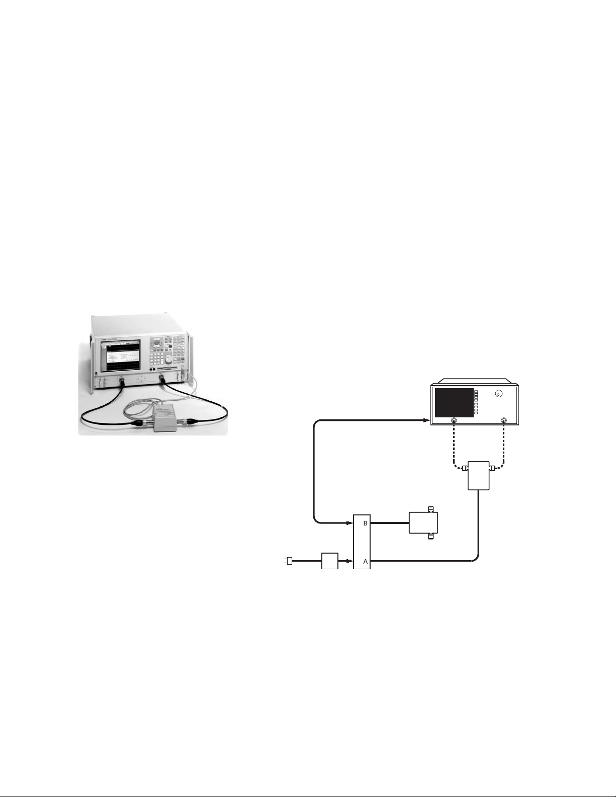
PNA and ENA Series
ECal modules are controlled
directly from the PNA and ENA
Series network analyzers. No
external PC is required. Simply
connect the ECal module to the
USB port on the network analyzer. You can control your calibration from the front panel keys of
the PNA Series or automatically
by your user program.
8719, 8720, 8722 and 8753
product families
ECal modules are controlled
manually or automatically via
the 85097B interface kit. The
85097B consists of an interface
unit and a power supply.
The interface module is the
interface between the parallel
port on your VNA, the parallel
port of the ECal module and the
external power supply.
Parallel port
connection
Firmware revisions of 7.68 or
higher in the 8753 and 8720
families allow for VNA control
of ECal modules. The 85097B
interface module, with the
analyzer’s internal firmware
control, provides digital control
and supplies power to one or
two ECal modules. Calibration
control is available via the front
panel keys or from a user
program. Firmware revision 7.74
and adapter cable (8121-1047) are
required for the N4690 Series.
The adapter cable can be ordered
as an option with the 85097B.
Network analyzer
Calibration configuration using the PNA series
VNA interface
unit
VNA interface
power supply
to AC power
Calibration configuration using the 85097B VNA interface kit
Optional
ECal module
ECal module
3
Page 4
Simple
Non-insertable
Calibrations
Most common RF and
microwave components have
non-insertable connectors; for
example, devices with female
connectors on both ports. These
devices require an adapter
removal calibration, which adds
an uncertainty factor to the
measurement. Most modern
vector network analyzers use an
adapter removal technique,
which compensates for adaptercaused errors.
The simplest and fastest noninsertable calibration method
uses an ECal module with
connectors that match your
device, and the same calibration
method as insertable devices.
Simply order your ECal module
with connectors that match your
device under test:
• Option 00M, male connectors
on both ports
• Option 00F, female connectors
on both ports.
• Option M0F with one male
and one female connector.
Perform adapter removal
calibrations faster
Some analyzers, such as later
versions of the 8753 and 8720,
offer adapter removal calibration
for non-insertable and mixed
connector measurement capability. Since this method requires
two full two-port calibrations, it
is often time consuming and
prone to operator errors. Using
ECal to perform the two-port
calibrations addresses both of
these concerns by reducing the
calibration time and the number
of connections, simplifying the
overall adapter removal process.
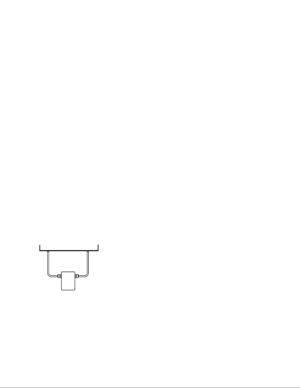
Perform a Usercharacterization
Normally, when you perform a
calibration with an ECal module,
the error terms for a calibration
are computed using the factory
characterization (data) stored in
the module. User-characterization allows you to change the
characterization of the module
in two ways:
• Change the connector
configuration: allows you to
add an adapter or fixture to
the test port of the module
and embed the effects into
the characterization of the
module. The result of the new
characterization extends the
reference plane from one or
more of the module’s test
ports to those on the adapter
(or fixture).
• Modify the state settings: allows
you to specify the number of
data points (1601 maximum)
or other stimulus settings the
module uses to perform a calibration.
Test set
ECal module
4
When you perform a user-characterization, the factory characterization data remains stored in the
module’s memory. At calibration,
you can select the factory
characterization or any of the
user-defined characterizations
stored in the module. The module
can store up to five user-defined
characterizations (in addition to
the factory characterization data).
User-characterization is available
with PNA and ENA Series
Network Analyzers.
Page 5

Input Power Level
Before performing a calibration, make sure the input power and DC levels do not exceed the values indicated in the table below.
Input power limits
ECal module series
Parameter 8509x N4431x N4432A/N4433A N469x
Typical maximum input power
Typical maximum DC level
applied to test port
Typical damage level +20.0 dBm +20.0 dBm +20.0 dBm +10.0 dBm
Operating temperature
The temperature of the ECal module must be within the following temperature range to meet the operating specifications.
• 8509x Series: +20 to +30 °C
• N443xA/B Series: +20 to +30 °C
• N469xA/B Series: +20 to +26 °C
1, 2
+9.0 dBm +7.0 dBm –7.0 dBm –5.0 dBm
±20 Volts ±3 Volts ±3 Volts ±10 Volts
Electrical characteristic corrected performance
(Residual e-terms)
2-port ECal modules
Type-F
85099C (RF)
Frequency range 300 kHz to 10 MHz 10 MHz to 300 MHz 300 MHz to 1.3 GHz 1.3 to 3 GHz
Directivity (dB) 45 50 48 43
Source match (dB) 36 48 45 38
Reflection tracking (±dB) 0.1 0.03 0.07 0.15
Transmission tracking (±dB) 0.08 0.08 0.10 0.17
Load match (dB) 39 43 41 39
3
1. If the maximum input power is exceeded when calibrating, compression may occur.
2. When using the PNA-X, the power level can be increased after calibration with minimal impact on measurement accuracy.
3. When mated with male connectors with a 0.77 mm (0.030 in) to 0.86 mm (0.034 in) pin diameter
5
Page 6

Type-N (50 ohms)
85092C (RF)
Frequency range 300 kHz to 10 MHz 10 MHz to 1 GHz 1 to 3 GHz 3 to 6 GHz 6 to 9 GHz
Directivity (dB) 45 52 54 52 47
Source match (dB) 36 45 44 41 36
Reflection tracking (±dB) 0.1 0.04 0.04 0.06 0.07
Transmission tracking (±dB) 0.078 0.04 0.04 0.07 0.14
Load match (dB) 39 47 47 44 39
1
N4690B (microwave)
Frequency range 300 kHz to 2 MHz 2 MHz to 10 MHz 10 to 500 MHz 500 MHz to 2 GHz 2 to 10 GHz 10 to 18 GHz
Directivity (dB) 30 40 45 48 46 42
Source match (dB) 28 35 40 43 40 35
Reflection tracking (±dB) 0.12 0.07 0.05 0.03 0.03 0.05
Transmission tracking (±dB) 0.15 0.12 0.08 0.07 0.07 0.12
Load match (dB) 24 29 35 42 41 38
2
Type-N (75 ohms)
85096C (RF)
Frequency range 300 kHz to 10 MHz 10 MHz to 300 MHz 300 MHz to 1.3 GHz 1.3 to 3 GHz
Directivity (dB) 45 50 48 43
Source match (dB) 36 48 45 38
Reflection tracking (±dB) 0.1 0.03 0.06 0.10
Transmission tracking (±dB) 0.08 0.08 0.09 0.16
Load match (dB) 39 43 41 39
3.5 mm
85093C (RF)
Frequency range 300 kHz to 10 MHz 10 MHz to 1 GHz 1 to 3 GHz 3 to 6 GHz 6 to 9 GHz
Directivity (dB) 45 52 52 50.5 47
Source match (dB) 36 44 44 39 34
Reflection tracking (±dB) 0.1 0.03 0.04 0.05 0.07
Transmission tracking (±dB) 0.078 0.04 0.06 0.07 0.12
Load match (dB) 39 47 47 44 40
1
3
1
N4691B (microwave)
Frequency range 300 kHz to 2 MHz 2 to 10 MHz 10 to 500 MHz 500 MHz to 2 GHz 2 to 10 GHz 10 to 20 GHz 20 to 26.5 GHz
Directivity (dB) 31 41 46 56 54 48 44
Source match (dB) 29 36 41 47 45 44 40
Reflection tracking (±dB) 0.11 0.06 0.05 0.02 0.03 0.04 0.05
Transmission tracking (±dB) 0.14 0.11 0.07 0.05 0.07 0.1 0.12
Load match (dB) 26 31 37 45 49 45 40
1. When applied power exceeds +9 dBm, calibration results will be degraded from the performance indicated in the table.
2. When applied power exceeds –5 dBm, calibration results will be degraded from the performance indicated in the table.
3. 3.5 mm modules have precision slotless connectors that guarantee the best calibration accuracy is transferred to your system.
2
6
Page 7

7 mm
85091C (RF)
Frequency range 300 kHz to 10 MHz 10 MHz to 1 GHz 1 to 3 GHz 3 to 6 GHz 6 to 9 GHz
Directivity (dB) 45 52 56 55 45
Source match (dB) 36 45 44 41 34
Reflection tracking (±dB) 0.1 0.04 0.04 0.07 0.10
Transmission tracking (±dB) 0.078 0.06 0.06 0.13 0.23
Load match (dB) 39 47 47 46 39
N4696B (microwave)
Frequency range (GHz) 300 kHz to 2 MHz 2 to 10 MHz 10 to 500 MHz 500 MHz to 2 GHz 2 to 10 GHz 10 to 18 GHz
Directivity (dB) 30 40 46 45 50 42
Source match (dB) 28 35 40 40 42 36
Reflection tracking (±dB) 0.12 0.07 0.05 0.03 0.03 0.05
Transmission tracking (±dB) 0.14 0.11 0.07 0.04 0.07 0.1
Load match (dB) 25 30 36 40 45 39
1
2
7-16
85098C (RF)
Frequency range 300 kHz to 10 MHz 10 MHz to 1 GHz 1 to 3 GHz 3 to 6 GHz 6 to 7.5 GHz
Directivity (dB) 45 47 50 46 45
Source match (dB) 36 43 43 38 37
Reflection tracking (±dB) 0.1 0.03 0.03 0.05 0.06
Transmission tracking (±dB) 0.078 0.05 0.06 0.08 0.10
Load match (dB) 39 42 43 41 38
1
2.92 mm
N4692A (microwave)
Frequency range (GHz) 10 to 45 MHz, typical 45 MHz to 2 GHz 2 to 20 MHz 20 to 30 GHz 30 to 40 GHz
Directivity (dB) 35 45 43 39 38
Source match (dB) 30 36 35 30 29
Reflection tracking (±dB) 0.10 0.08 0.08 0.10 0.10
Transmission tracking (±dB) 0.10 0.14 0.14 0.20 0.25
Load match (dB) 27 36 37 33 33
2
2.4 mm
N4693A (microwave)
Frequency range (GHz) 10 to 45 MHz, typical 45 MHz to 2 GHz 2 to 10 MHz 10 to 20 GHz 20 to 40 GHz 40 to 50 GHz
Directivity (dB) 32 55 49 45 43 41
Source match (dB) 25 46 42 37 35 30
Reflection tracking (±dB) 0.05 0.03 0.04 0.05 0.06 0.08
Transmission tracking (±dB) 0.10 0.06 0.08 0.11 0.13 0.17
Load match (dB) 24 45 42 40 38 36
2
1. When applied power exceeds +9 dBm, calibration results will be degraded from the performance indicated in the table.
2. When applied power exceeds –5 dBm, calibration results will be degraded from the performance indicated in the table.
7
Page 8

1.85 mm
N4694A (microwave)
Frequency range (GHz) 10 to 45 MHz 45 MHz to 2 GHz 2 to 20 GHz 20 to 30 GHz 30 to 40 GHz 40 to 50 GHz 50 to 60 GHz 60 to 67 GHz
Directivity (dB) 33 50 50 46 44 42 41 38
Source match (dB) 25 38 39 35 34 33 30 27
Reflection tracking (±dB) 0.05 0.04 0.04 0.05 0.06 0.07 0.08 0.09
Transmission tracking (±dB) 0.15 0.07 0.1 0.11 0.13 0.15 0.19 0.25
Load match (dB) 25 41 44 42 40 38 36 32
1
4-port modules
Type-N (50 ohms)
N4431B (RF), Option 020
Frequency range 9 kHz3to 10 MHz 10 MHz to 1 GHz 1 to 3 GHz 3 to 6 GHz 6 to 8 GHz 8 to 9 GHz 9 to 13.5 GHz
Thru paths AB, CD, AD, BC
Directivity (dB) 45 55 52 47 44 42 40
Source match (dB) 36 47 43 42 40 39 31
Reflection tracking (±dB) 0.10 0.03 0.04 0.04 0.05 0.06 0.11
Transmission tracking (±dB) 0.078 0.07 0.10 0.14 0.20 0.22 0.35
Load match (dB) 39 47 45 40 38 35 26
Thru paths AC, BD
Directivity (dB) 45 55 52 47 44 42 40
Source match (dB) 36 47 43 42 40 39 31
Reflection tracking (±dB) 0.10 0.03 0.04 0.04 0.05 0.06 0.11
Transmission tracking (±dB) 0.078 0.07 0.09 0.13 0.15 0.16 0.32
Load match (dB) 39 47 45 40 38 36 28
2
4
3.5 mm
N4431B (RF), Option 010
Frequency range 9 kHz3to 10 MHz 10 MHz to 1 GHz 1 to 3 GHz 3 to 6 GHz 6 to 8 GHz 8 to 9 GHz 9 to 13.5 GHz
Thru paths AB, CD, AD, BC
Directivity (dB) 45 57 55 52 50 47 40
Source match (dB) 36 50 47 45 44 43 32
Reflection tracking (±dB) 0.10 0.03 0.03 0.04 0.04 0.05 0.1
Transmission tracking (±dB) 0.078 0.06 0.09 0.12 0.14 0.20 0.33
Load match (dB) 39 47 46 45 44 42 28
Thru paths AC, BD
Directivity (dB) 45 57 55 52 50 47 40
Source match (dB) 36 50 47 45 44 43 32
Reflection tracking (±dB) 0.10 0.03 0.03 0.04 0.04 0.05 0.1
Transmission tracking (±dB) 0.078 0.06 0.08 0.10 0.12 0.14 0.3
Load match (dB) 39 47 46 45 45 43 29
1. When applied power exceeds –5 dBm, calibration results will be degraded from the performance indicated in the table.
2. When applied power exceeds +7 dBm, calibration results will be degraded from the performance indicated in this table.
3. Performance from 9 kHz to 300 kHz is valid only for the E5071C ENA network analyzer with firmware version A.09.10 or higher.
4. 9 to 13.5 GHz range not vaild for the N4431A
8
2
4
Page 9

Type-N (50 ohms)
N4432A
The characteristic performance in the following table applies to N4432A Option 020 (3.5 mm female connectors on all ports).
Characteristic performance for N4432A Option 020
Frequency range 300 kHz to 10 MHz 10 MHz to 5 GHz 5 to 9 GHz 9 to 13.5 GHz 13.5 to 18 GHz
Parameter
Directivity (dB) 45 52 47 41 42
Source match (dB) 35 41 37 34 34
Reflection tracking (±dB) 0.1 0.06 0.1 0.15 0.14
Transmission tracking (±dB)
Load match (dB)
2
2
0.082 0.046 0.062 0.089 0.084
39 45 40 36 37
1
3.5 mm
N4433A
The characteristic performance in the following table applies to N4433A Option 010 (3.5 mm female connectors on all ports).
Characteristic performance for N4433A Option 010
Frequency range 300 kHz to 10 MHz 10 MHz to 5 GHz 5 to 9 GHz 9 to 13.5 GHz 13.5 to 20 GHz
Parameter
Directivity (dB) 45 52 47 45 45
Source match (dB) 36 42 39 37 31
Reflection tracking (±dB) 0.1 0.06 0.09 0.10 0.18
Transmission tracking (±dB)
Load match (dB)
2
2
0.078 0.045 0.057 0.069 0.160
39 45 41 39 35
1
1. When applied power exceeds –7 dBm, calibration results will be degraded from the performance indicated in this table.
2. Values based on using the PNA Network Analyzer N5230A Option 240 or 245
9
Page 10

Ordering information
1
Select an ECal module based
on the connector type required
and the frequency range of your
vector network analyzer (refer
to table below).
Notes:
1. Order the 85097B interface module
if you will be using ECal with your
8719, 8720, 8722 or 8753. (Please
reference the ECal and network
analyzer/firmware compatibility
table on page 3.) The 85097B consists of an interface module and a
power supply.
2. When using the N469x ECal products with the 8720 or 8753 network
analyzer families, an adapter cable
(8121-1047) is needed. This adapter
cable is orderable as an option
with the 85097B.
ECal modules and available options
2-port
Connector Frequency range ECal module Available options
Type model number
Type-F 300 kHz to 3 GHz 85099C 00A, 00F, 00M, UK6, M0F
Type-N 300 kHz to 9 GHz 85092C 00A, 00F, 00M, UK6, 1A7, A6J, M0F,
50 ohms mixed-connectors
Type-N 300 kHz to 18 GHz N4690B 00A, 00F, 00M, UK6, 1A7, A6J, M0F
50 ohms
Type-N 300 kHz to 3 GHz 85096C 00A, 00F, 00M, UK6, M0F
75 ohms
3.5 mm 300 kHz to 9 GHz 85093C 00A, 00F, 00M, UK6, 1A7, A6J, M0F
mixed connectors
3.5 mm 300 kHz to 26.5 GHz N4691B 00A, 00F, 00M, UK6, 1A7, A6J, M0F
7 mm 300 kHz to 9 GHz 85091C UK6, 1A7, A6J
7 mm 300 kHz to 18 GHz N4696B UK6, 1A7, A6J
7-16 300 kHz to 7.5 GHz 85098C 00A, 00F, 00M, UK6, M0F, mixed-connectors
2.92 mm 10 MHz to 40 GHz N4692A 00A, 00F, 00M, UK6, 1A7, A6J, M0F
2.4 mm 10 MHz to 50 GHz N4693A 00A, 00F, 00M, UK6, 1A7, A6J, M0F
1.85 mm 10 MHz to 67 GHz N4694A 00A, 00F, 00M, UK6, 1A7, A6J, M0F
4-port
Connector Frequency range ECal module Available options
Type model number
3.5 mm or 9 kHz to 13.5 GHz N4431B 010, 020, UK6, 1A7, A6J, mixed-connectors
Type-N
50 ohms
Type-N 300 kHz to 18 GHz N4432A 020, mixed-connectors
50 ohms
3.5 mm 300 kHz to 20 GHz N4433A 010
Options
Option Description
00F Replace f-m connectors on ECal module(s) with f-f connectors
00M Replace f-m connectors on ECal module(s) with m-m connectors
00A Adds male-to-male and female-to-female adapters (also adds a 5/16” 90 N-cm (8 in-lb)
torque wrench to 3.5 mm modules)
1A7 ISO 17025 compliant calibration
A6J ANSI Z540 compliant calibration
UK6 Commercial calibration certificate with measured data
M0F f-m connectors on ECal module(s)
010 Four female, 3.5 mm connectors
020 Four female, Type-N 50 ohm connectors
1. Performance from 9 kHz to 300 KHz is valid only for the E5071C ENA network analyzer with firmware version A.09.10 or higher.
10
Page 11

Mixed-connector options
2-port (85092C/3C/8C ECal modules only)
Port A option Port B option
Model number Type (f) (m) Type (f) (m) Type (f) (m)
85092C Type-N 50 ohm 103 104 3.5 mm 201 202 7-16
85093C 3.5 mm 101 102 Type-N 50 ohm 203 204 7-16
85098C 7-16
1
105 106 3.5 mm 201 202 Type-N 50 ohm 203 204
4-port (N4431B ECal module only)
Connector type Port A option Port B option Port C option Port D option
3.5 mm (f) 101 201 301 401
3.5 mm (m) 102 202 302 402
Type-N 50 ohm (f) 103 203 303 403
Type-N 50 ohm (m) 104 204 304 404
1
7-16 (f)
7-16 (m)
1
105 205 305 405
106 206 306 406
4-port (N4432A ECal module only)
Connector type Port A option Port B option Port C option Port D option
3.5 mm (f) 101 201 301 401
3.5 mm (m) 102 202 302 402
Type-N 50 ohm (f) 103 203 303 403
Type-N 50 ohm (m) 104 204 304 404
1
1
205 206
205 206
1. Limits ECal module high frequency to 7.5 GHz.
11
Page 12

Web Resources
Visit our Web sites, for additional
product information and literature.
Electronic calibration (ECal):
www.agilent.com/find/ecalPNA
Series network analyzers:
www.agilent.com/find/pna
Test and measurement accessories:
www.agilent.com/find/accessories
www.agilent.com/find/emailupdates
Get the latest information on the
products and applications you select.
www.agilent.com/find/agilentdirect
Quickly choose and use your test
equipment solutions with confidence.
www.agilent.com/find/open
Agilent Open simplifies the process
of connecting and programming
test systems to help engineers
design, validate and manufacture
electronic products. Agilent offers
open connectivity for a broad range
of system-ready instruments, open
industry software, PC-standard I/O
and global support, which are
combined to more easily integrate
test system development.
Remove all doubt
Our repair and calibration services
will get your equipment back to you,
performing like new, when promised. You will get full value out of
your Agilent equipment throughout its lifetime. Your equipment
will be serviced by Agilent-trained
technicians using the latest factory
calibration procedures, automated
repair diagnostics and genuine parts.
You will always have the utmost
confidence in your measurements.
For information regarding self
maintenance of this product, please
contact your Agilent office.
Agilent offers a wide range of additional expert test and measurement services for your equipment,
including initial start-up assistance,
onsite education and training, as
well as design, system integration,
and project management.
For more information on repair and
calibration services, go to:
www.agilent.com/find/removealldoubt
Product specifications and descriptions
in this document subject to change
without notice.
www.agilent.com
For more information on Agilent Technologies’ products, applications or services,
please contact your local Agilent office.
The complete list is available at:
www.agilent.com/find/contactus
Americas
Canada (877) 894-4414
Latin America 305 269 7500
United States (800) 829-4444
Asia Pacific
Australia 1 800 629 485
China 800 810 0189
Hong Kong 800 938 693
India 1 800 112 929
Japan 0120 (421) 345
Korea 080 769 0800
Malaysia 1 800 888 848
Singapore 1 800 375 8100
Taiwan 0800 047 866
Thailand 1 800 226 008
Europe & Middle East
Austria 01 36027 71571
Belgium 32 (0) 2 404 93 40
Denmark 45 70 13 15 15
Finland 358 (0) 10 855 2100
France 0825 010 700*
*0.125 €/minute
Germany 07031 464 6333
Ireland 1890 924 204
Israel 972-3-9288-504/544
Italy 39 02 92 60 8484
Netherlands 31 (0) 20 547 2111
Spain 34 (91) 631 3300
Sweden 0200-88 22 55
Switzerland 0800 80 53 53
United Kingdom 44 (0) 118 9276201
Other European Countries:
www.agilent.com/find/contactus
Revised: October 6, 2008
© Agilent Technologies, Inc. 2002-2009
Printed in USA, February 3, 2009
5963-3743E
Windows®and Windows NT®are U.S.
registered trademarks of Microsoft Corp.
 Loading...